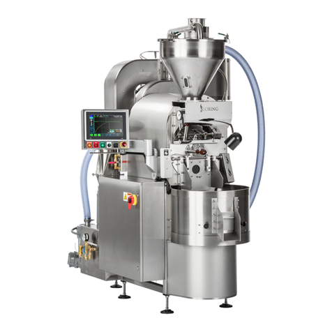
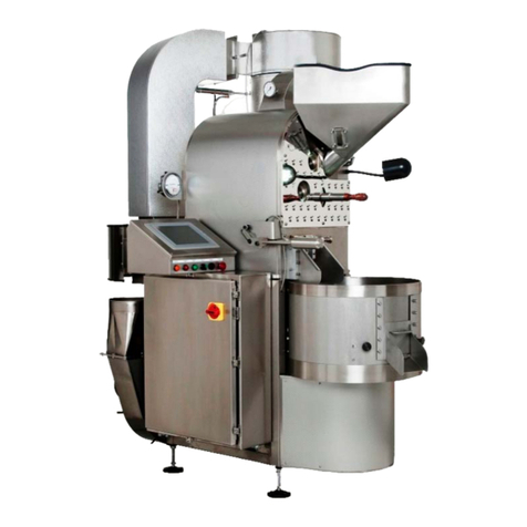
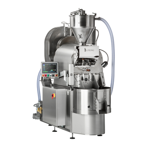
Loring S15 Falcon User manual

Pre-Installation and Site
Preparation Guide
Loring S15 Falcon Coffee Roaster
TM

S15 Pre-Installation and Site Preparation Guide
Page 2 of 46 Loring Smart Roast Proprietary – This document is controlled by
Document Control. By printing this document, it will become a “Reference” copy.
Users are responsible for verifying that it is the latest revision available.
1008236 Rev B
This page intentionally left blank.

S15 Pre-Installation and Site Preparation Guide
1008236 Rev B Loring Smart Roast Proprietary – This document is controlled by
Document Control. By printing this document, it will become a “Reference” copy.
Users are responsible for verifying that it is the latest revision available.
Page 3 of 46
Notices
Document Versioning Information
This manual, along with other manuals in this series, is intended to be a guideline for the installation
and use for the product lines manufactured by Loring Smart Roast, Inc. The customer is responsible
for complying with all applicable regulations.
The customer should refer to a licensed professional contractor or contractors for all installation
details.
© Loring Smart Roast, Inc. All rights reserved.
The name LORING SMART ROAST, the Loring logo, and the catchphrase “The Smarter Way To
Roast” are all trademarks of Loring Smart Roast, Inc.
Warranty is void unless product is installed and used in accordance with all written instructions.
Throughout this manual, the following signal words are used to identify the degree of seriousness in
any operation that presents a potentially hazardous situation.
Dangers, Warnings, and Cautions
Document No. 1008236 Rev B
Date Last Exported: September 3, 2018
DANGER: Indicates a hazard that WILL cause severe personal injury, death, or substantial
property damage if ignored.
WARNING: Indicates a hazard that could cause SEVERE personal injury, death, or
substantial property damage if ignored.
CAUTION: Indicates a hazard that could cause MINOR personal injury or property damage
if ignored.

S15 Pre-Installation and Site Preparation Guide
Page 4 of 46 Loring Smart Roast Proprietary – This document is controlled by
Document Control. By printing this document, it will become a “Reference” copy.
Users are responsible for verifying that it is the latest revision available.
1008236 Rev B
Follow all written instructions provided by Loring, and verbal instructions from Loring Customer
Support, regarding site preparation prior to receiving the coffee roasting equipment.
All contractors or subcontractors involved in installation or working with specic connections (e.g.,
water, air, gas, electrical, hot and cold exhaust ventilation) should be fully licensed and qualied in
that particular functional area.
Comply with all applicable rules and regulations and governing agencies.
Loring reserves the right to change information within this document at any time without notice.
Pre-Installation and Site Preparation Guide General Notes

S15 Pre-Installation and Site Preparation Guide
1008236 Rev B Loring Smart Roast Proprietary – This document is controlled by
Document Control. By printing this document, it will become a “Reference” copy.
Users are responsible for verifying that it is the latest revision available.
Page 5 of 46
Contents
Introduction _________________________________________________ 7
Audience _______________________________________________ 7
Acquiring a Coffee Roaster _________________________________ 7
S15 Specications____________________________________________ 9
Requirements for Utilities ___________________________________10
Power Specication _______________________________________11
Dimensions and Clearances____________________________________13
Overall Footprint__________________________________________13
Footprint – S15 Roaster ____________________________________14
Floor Clearances – S15 Roaster _____________________________15
Overhead Clearances – S15 Roaster _________________________16
Footprint - S15 Roaster Feet ________________________________17
45-Degree Vent Kit ________________________________________18
Space Planning ______________________________________________20
Indoors _________________________________________________20
Floor ___________________________________________________20
Stack Connection Location _________________________________21
Door Openings ___________________________________________22
Local Codes _____________________________________________23
Utilities _________________________________________________23
Room Size and Ventilation __________________________________23
Low Ceiling______________________________________________24
Multi-Story Buildings_______________________________________24
Workow Space __________________________________________25
Lighting_________________________________________________27
Network ________________________________________________27

S15 Pre-Installation and Site Preparation Guide
Page 6 of 46 Loring Smart Roast Proprietary – This document is controlled by
Document Control. By printing this document, it will become a “Reference” copy.
Users are responsible for verifying that it is the latest revision available.
1008236 Rev B
Receiving Shipment __________________________________________28
Shipping Notes___________________________________________28
S15 Shipping Crate _______________________________________29
Lifting and Moving the Roaster_______________________________31
Next Steps __________________________________________________34
Site Preparation Checklist __________________________________34
Gas and Gas Supply __________________________________________35
Propane Fuel Installation Specications _______________________36
Natural Gas Installation Specications_________________________37
Installing the Vent Stack _______________________________________38
Vent Stack Congurations __________________________________40
Adjusting Roaster to the Vent Stack __________________________44
Manufacturer Contact Information_______________________________46

S15 Pre-Installation and Site Preparation Guide
1008236 Rev B Loring Smart Roast Proprietary – This document is controlled by
Document Control. By printing this document, it will become a “Reference” copy.
Users are responsible for verifying that it is the latest revision available.
Page 7 of 46
Introduction
Audience
Acquiring a Coffee Roaster
The intended audience for this manual, the S15 Pre-Installation and Site Preparation Guide,
includes customer-side administrators, oor employees, general contractors, facilities managers
and other individuals who are responsible for preparing the site for installation of the roaster.
Preparing for and installing a Loring coffee roaster requires cooperation between the customer
and Loring over several weeks. Generally, the customer should begin preparing the site 3 months
prior to shipping. Upon receiving the roaster, the customer’s general contractor assembles
the roaster, connects the utilities including water, gas, and electric, connects the hot and cold
exhaust ventilation, and then waits for the Loring Field Service Technician to perform nal system
commissioning. The commissioning period also includes hands-on customer training in the use and
maintenance of the roaster.
Some tasks, such as ordering stack ventilation components, may require specifying and purchasing
equipment from third-party suppliers. Allow sufcient lead times.
WARNING: Operating the roaster prior to nal inspection and commissioning by an
authorized Loring Field Service Technician will void the warranty.

S15 Pre-Installation and Site Preparation Guide
Page 8 of 46 Loring Smart Roast Proprietary – This document is controlled by
Document Control. By printing this document, it will become a “Reference” copy.
Users are responsible for verifying that it is the latest revision available.
1008236 Rev B
Additional Documentation
The following additional documentation is available to aid with installation and setup. Contact your
Loring Account Representative for more information.
• Welcome Packet. The Welcome Packet contains detailed instructions and information sent
by Loring to each new customer upon purchase of a coffee roaster. One item, the Product
Specication Form, must be completed and returned to Loring in order for Loring to begin
building the roaster.
• Product Specication Form (PSF). The customer must provide information to Loring regarding
the site’s utility characteristics. This information is used to congure the roaster at the factory,
a process that requires several weeks’ lead time. Loring strongly recommends working with a
licensed professional contractor when providing this information. This form is included in the
Welcome Packet.
• Suggested Stack Manufacturers. One of the items in the Welcome Packet is a list of
recommended manufacturers of stack ventilation components. Loring recommends ordering
stacks 6 weeks prior to the arrival of the roaster.
• Installation and Assembly Guide. After receiving the coffee roaster, the customer must engage
with a licensed general contractor to assemble, position, and hook up the roaster to various
utilities and stack ventilation.
• Mechanical Interface Control Documents (MICDs). These technical drawings provide detailed
information on system dimensioning and components, as well as system weights. They are
intended for permit submittals and for use by general contractors, as well as by architects and
facilities planners. These drawings are available upon request from Loring.
• Special Reports for Permitting. Additional reports on various technical subjects are available
from Loring. Each customer may need to satisfy unique local or regional regulatory
requirements. For example, air quality reports are typically required, and some locations may
require both county and city permits.
The Product Specication Form (PSF) conveys extremely
important customer information regarding the customer
site’s power supply voltage and network conguration.
Loring requires this form to be completed by the customer
a minimum of 9 weeks prior to production completion.
Any delay in providing any portion of this information can
delay the roaster production by a corresponding number of
weeks.

S15 Pre-Installation and Site Preparation Guide
1008236 Rev B Loring Smart Roast Proprietary – This document is controlled by
Document Control. By printing this document, it will become a “Reference” copy.
Users are responsible for verifying that it is the latest revision available.
Page 9 of 46
S15 Specications
S15 Specication Value
System Weight 11573 lb (714 kg) uncrated
Maximum Batch Size 33 lb (15 kg)
Minimum Batch Size 6.6 lb (3 kg)
Nominal Electrical Power 2.8 kW
Peak Electrical Power 5.8 kW
Maximum BTU Rating 130,000 BTU/hr (33 K kcal/h)
Hot Stack Max Continuous Temperature 2 1400 °F (760 °C)
Hot Stack Max Intermittent Temperature 21500 °F (816 °C)
Hot Stack Max Flow 322 dscfm (37 dsm3/h)
Hot Stack Max Flow (Peak Air Cool) 5310 dscfm (527 dsm3/h)
Hot Stack Minimum Duct Diameter 46 in (152 mm)
Cooling Exhaust Max Flow 5980 scfm (1670 sm3/h)
Cooling Duct Diameter 46 in (152 mm)
Table 1. S15 Basic Equipment Specications
Notes:
1 Exact system weight may depend on options selected.
2 Consult local and regional regulations for air quality, temperature, and emissions restrictions.
3 Dry, or water content of the ue removed, under standard pressure and temperature conditions,
i.e. 29.9 in HG (760 mm HG) and 68°F (20°C).
4 Larger stack diameters or stack openings may be required under some conditions.
5 Add the Hot Stack Max Flow (Peak Air Cool) and Cooling Exhaust Max Flow to obtain the total
air ow out of the building. This may be needed in the event that additional air intake, otherwise
known as makeup air, is needed at the installation site.

S15 Pre-Installation and Site Preparation Guide
Page 10 of 46 Loring Smart Roast Proprietary – This document is controlled by
Document Control. By printing this document, it will become a “Reference” copy.
Users are responsible for verifying that it is the latest revision available.
1008236 Rev B
S15 Specication Value
Water Supply (Flow) Minimum 1 GPM (3.8 LPM) or greater
Water Pressure Minimum 50 psi (345 kPa) or greater
Compressed Air Flow, Minimum 4 CFM (0.11 m3 min) or greater
Compressed Air Pressure, Minimum 60 psi (414 kPa)
Natural Gas Pressure (Min/Max Range) 4 - 7 in WC (1.0 - 1.7 kPa)
Natural Gas Caloric Content, Minimum 1000 BTU/ft3 (37 MJ/m3) or greater
Propane Gas Pressure (Min/Max Range) 11 - 13 in WC (2.7 - 3.2 kPa)
Propane Gas Caloric Content, Minimum 2500 BTU/ft3 (93 MJ/m3) or greater
Requirements for Utilities
In order to ensure proper roaster performance, the customer should verify that the site utilities meet
basic requirements for water, compressed air, and gas. The customer must indicate whether the site
uses natural gas or propane.
Table 2. S15 Utilities Requirements

S15 Pre-Installation and Site Preparation Guide
1008236 Rev B Loring Smart Roast Proprietary – This document is controlled by
Document Control. By printing this document, it will become a “Reference” copy.
Users are responsible for verifying that it is the latest revision available.
Page 11 of 46
Power Specication
Loring coffee roasters can be built to accommodate a wide range of electrical congurations. To
determine which Loring topology matches your facility’s supply, the customer should engage a
licensed electrician to perform a site survey, in order to provide the following information.
On the Product Specication Form, the customer has the option to choose among some commonly
occurring congurations. However, the customer should NOT approximate by choosing the closest one
if it is not an exact match.
If the customer site is not represented, contact Loring immediately for other possible congurations.
For example, a typical U.S. installation might be 208 VAC, 3-phase, at 60 Hz.
This equates to a specication of 208 (3P) - 60
A typical installation in Europe might be 400 VAC, 3-phase, at 50 Hz.
This equates to a specication of 400 (3P) - 50
Supply Voltage Combinations
Power
Voltage:
200 (3P)
208 (1P)
208 (3P)
220 (3P)
230 (3P)
240 (1P)
240 (3P)
380 (3P)
400 (3P)
415 (3P)
480 (3P)
– – –
Power
Frequency:
50 - 50Hz
60 - 60 Hz
Model
Number:
Eg. S15
Gas Type:
NG - Natural Gas
LPG - Propane
Example: S15 - NG- 380 (3 P) - 50

S15 Pre-Installation and Site Preparation Guide
Page 12 of 46 Loring Smart Roast Proprietary – This document is controlled by
Document Control. By printing this document, it will become a “Reference” copy.
Users are responsible for verifying that it is the latest revision available.
1008236 Rev B
The information under Power Specication is as follows:
• Voltage: Designates the type of power voltage at the site.
»The L-L number is the Primary or Line-to-Line voltage.
»The L-N is the Secondary Line-to-Neutral voltage.
Note: A Neutral wire is no longer required for Loring Roasters.
• Number of Phases: The Number of Phases represents the number of Line-to-Line phases. This
is either 1P or 3P, indicating single phase or three phase respectively.
• Wiring Topology: The type of circuit. Refer to Loring Engineering Document No. 1001163 for
more information.
»Y= Wye
»D= Delta
• Power Frequency: The last informational block designates the site’s voltage frequency, in Hertz
(Hz).
In order for the roaster to function properly, the customer is responsible for installing service to the
required level of amperage as follows:
• 200 VAC – 240 VAC:
»1P – 30 Amps
»3P – 30 Amps
• 380 VAC – 480 VAC – 20 Amps
Supply Voltages, Explained
Supply Amperage
3-Phase Wye 3-Phase Delta

S15 Pre-Installation and Site Preparation Guide
1008236 Rev B Loring Smart Roast Proprietary – This document is controlled by
Document Control. By printing this document, it will become a “Reference” copy.
Users are responsible for verifying that it is the latest revision available.
Page 13 of 46
Dimensions and Clearances
Overall Footprint
Refer to the Mechanical Interface Control Document (MICD) from Loring
for further information, including CAD diagrams with construction details.
S15 Dimension Value
Footprint (Roaster only) 61" W x 91" L x 91” H
(155 cm W x 231 cm L x 231 cm H)
Clearance
29" left, 36” right, 26” front, 11" in back
(74 cm left, 91 cm right, 66 cm front, 27 cm
back)
Roaster Height 91" (231 cm)
Minimum Ceiling Clearance 12" (31 cm) above Stack Hat
Total Ceiling Height 103" (262 cm)
Table 3. S15 Dimensions and Clearances

S15 Pre-Installation and Site Preparation Guide
Page 14 of 46 Loring Smart Roast Proprietary – This document is controlled by
Document Control. By printing this document, it will become a “Reference” copy.
Users are responsible for verifying that it is the latest revision available.
1008236 Rev B
Front
Left Right
Back
Footprint – S15 Roaster
Roaster
Electrical enclosure
door opening, 29"
(61 cm) radius
Width: 61" (155 cm)
Length: 91" (231 cm)

S15 Pre-Installation and Site Preparation Guide
1008236 Rev B Loring Smart Roast Proprietary – This document is controlled by
Document Control. By printing this document, it will become a “Reference” copy.
Users are responsible for verifying that it is the latest revision available.
Page 15 of 46
Front
Left Right
Back
Floor Clearances – S15 Roaster
Roaster
Left Side
Clearance:
29" (74 cm) Right Side Clearance:
36" (91 cm)
Back Clearance:
11" (27 cm)

S15 Pre-Installation and Site Preparation Guide
Page 16 of 46 Loring Smart Roast Proprietary – This document is controlled by
Document Control. By printing this document, it will become a “Reference” copy.
Users are responsible for verifying that it is the latest revision available.
1008236 Rev B
Overhead Clearances – S15 Roaster
Overhead clearance should accommodate the roaster plus a minimum stack height.
This clearance is also necessary for routine maintenance, as well as providing room to
maneuver during installation.
Minimum Total Ceiling Height: 103" (262 cm)
Clearance:
12"
(31 cm)
Height:
91"
(231 cm)

S15 Pre-Installation and Site Preparation Guide
1008236 Rev B Loring Smart Roast Proprietary – This document is controlled by
Document Control. By printing this document, it will become a “Reference” copy.
Users are responsible for verifying that it is the latest revision available.
Page 17 of 46
Footprint - S15 Roaster Feet
The roaster rests on 5 Roaster Feet, which support the entire weight of the roaster and
allow for leveling on uneven oor surfaces. The oor must be able support the concentrated
weight.
Note that total system weight may vary depending on options selected. The S15 roaster
alone weighs1573 lb (714 kg). Most of this weight is concentrated in the 4 Roaster Feet
that are under the roaster body itself.
For dimensions of roaster feet
spacing, contact Loring Support
for the S15 MICD.

S15 Pre-Installation and Site Preparation Guide
Page 18 of 46 Loring Smart Roast Proprietary – This document is controlled by
Document Control. By printing this document, it will become a “Reference” copy.
Users are responsible for verifying that it is the latest revision available.
1008236 Rev B
45-Degree Vent Kit
The 45-Degree Vent Kit is an optional 2-piece component set for the Cooling Exhaust Vent that
acts as an extender. It provides additional range for positioning the exit point, including rotating
around the roaster attachment point, and can be removed to facilitate cleaning of the Cooling
Vent.
This kit is a special order item. If needed, it is shipped with the roaster in the Accessory crate.
2” (5cm)
19”
(48 cm) 17”
(43 cm)

S15 Pre-Installation and Site Preparation Guide
1008236 Rev B Loring Smart Roast Proprietary – This document is controlled by
Document Control. By printing this document, it will become a “Reference” copy.
Users are responsible for verifying that it is the latest revision available.
Page 19 of 46
45-Degree Vent Kit Rotation
25 degrees forward
from straight side
orientation
120 degrees total
rotation range
Top Down Views
Radius of
Rotation:
9.3" (23.6 cm)

S15 Pre-Installation and Site Preparation Guide
Page 20 of 46 Loring Smart Roast Proprietary – This document is controlled by
Document Control. By printing this document, it will become a “Reference” copy.
Users are responsible for verifying that it is the latest revision available.
1008236 Rev B
Indoors
Floor
Flat and Level No Soft Spots
Space Planning
Locate the coffee roaster in an area
that is protected from the elements
and from water intrusion. The
area does not need to be a fully
conditioned space.
Place the roaster on a at, level, and rm
surface such as hard wood or concrete.
The oor should be strong enough to
support the total system weight of the
roaster and all supplemental equipment.
CAUTION: Use care when transporting the
equipment over bumpy or uneven ooring.
WARNING: Do not place the roaster on a soft
or unstable surface.
Other manuals for S15 Falcon
1
Table of contents
Other Loring Kitchen Appliance manuals