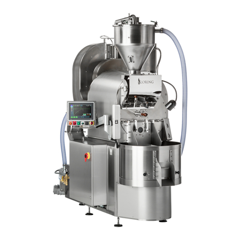
Loring S15 Falcon User manual

Assembly and Installation Guide
Loring S15 Falcon Coffee Roaster
TM

S15 Assembly and Installation Guide
Page 2 of 50 Loring Smart Roast Proprietary – This document is controlled by
Document Control. By printing this document, it will become a “Reference” copy.
Users are responsible for verifying that it is the latest revision available.
1008286 Rev B
This page intentionally left blank.

S15 Assembly and Installation Guide
1008286 Rev B Loring Smart Roast Proprietary – This document is controlled by
Document Control. By printing this document, it will become a “Reference” copy.
Users are responsible for verifying that it is the latest revision available.
Page 3 of 50
Notices
Document Versioning Information
This manual, along with other manuals in this series, is intended to be a guideline for the installation
and use for the product lines manufactured by Loring Smart Roast, Inc. The customer is responsible
for complying with all applicable regulations.
The customer should refer to a licensed professional contractor or contractors for all installation
details.
© Loring Smart Roast, Inc. All rights reserved.
The name LORING SMART ROAST, the Loring logo, and the catchphrase “The Smarter Way To
Roast” are all trademarks of Loring Smart Roast, Inc.
Warranty is void unless product is installed and used in accordance with all written instructions.
Throughout this manual, the following signal words are used to identify the degree of seriousness in
any operation that presents a potentially hazardous situation.
Dangers, Warnings, and Cautions
Document No. 1008286 Rev B
Date Last Exported: September 3, 2018
DANGER: Indicates a hazard that WILL cause severe personal injury, death, or substantial
property damage if ignored.
WARNING: Indicates a hazard that could cause SEVERE personal injury, death, or
substantial property damage if ignored.
CAUTION: Indicates a hazard that could cause MINOR personal injury or property damage
if ignored.

S15 Assembly and Installation Guide
Page 4 of 50 Loring Smart Roast Proprietary – This document is controlled by
Document Control. By printing this document, it will become a “Reference” copy.
Users are responsible for verifying that it is the latest revision available.
1008286 Rev B
• Follow all written instructions provided by Loring, and verbal instructions from Loring Customer
Support, regarding site preparation prior to receiving the coffee roasting equipment.
• All contractors or subcontractors involved in installation or working with specic connections
(e.g., water, air, gas, electrical, hot and cold exhaust stacks) should be fully licensed and
qualied in that particular functional area.
• Comply with all applicable rules and regulations and governing agencies.
• Many of the roaster components have stainless steel fasteners attaching to stainless steel parts.
Stainless steel has a tendency to “seize” when over-tightened. Use care when fastening and
apply food-grade anti-seize compound to fastener threads.
• Loring reserves the right to change information within this document at any time without notice.
Assembly and Installation Guide General Notes

S15 Assembly and Installation Guide
1008286 Rev B Loring Smart Roast Proprietary – This document is controlled by
Document Control. By printing this document, it will become a “Reference” copy.
Users are responsible for verifying that it is the latest revision available.
Page 5 of 50
Contents
Introduction _________________________________________________ 7
Audience _______________________________________________ 7
Additional Documentation __________________________________ 7
Major Components, Assembled ______________________________ 8
Back View, Components, As Shipped _________________________ 9
Notes for Unpacking_______________________________________11
Uncrate the Roaster __________________________________________12
Attach Roaster Feet _______________________________________15
Assemble the Roaster_________________________________________18
Attach Vacuum Tube ______________________________________21
Attach the Cyclone________________________________________24
Attach Purge Gate Air Cylinder ______________________________26
Attach Gas Mixer Line _____________________________________27
Secure Cyclone Fasteners__________________________________28
Water Line (Chaff Quench Hose) _________________________29
High Temperature Cutoff Switch______________________________29
Connect the Ignition Wire______________________________________30
Burner Control Unit (BCU) Ignition____________________________31
Direct Spark Ignition (DSI) __________________________________33
Install the Thermocouples __________________________________36
Complete the Cyclone Installation_______________________________37
Final Roaster Assembly _______________________________________38
Attach Mini Cyclone _______________________________________38
Move Roaster to Final Location ______________________________40
Tryer Handle_____________________________________________40

S15 Assembly and Installation Guide
Page 6 of 50 Loring Smart Roast Proprietary – This document is controlled by
Document Control. By printing this document, it will become a “Reference” copy.
Users are responsible for verifying that it is the latest revision available.
1008286 Rev B
Adjust the Operator’s Console ______________________________41
Chaff Barrel _____________________________________________42
Roaster Feet ____________________________________________42
Compressed Air Supply ____________________________________42
Install the Roaster ____________________________________________43
Air, Gas, and Water Connections_____________________________44
Hot Air Exhaust Vent Connection_____________________________45
Cooling Air Exhaust Vent Connection__________________________46
Electrical and Network Connections___________________________47
Next Steps __________________________________________________48
Manufacturer Contact Information_______________________________50

S15 Assembly and Installation Guide
1008286 Rev B Loring Smart Roast Proprietary – This document is controlled by
Document Control. By printing this document, it will become a “Reference” copy.
Users are responsible for verifying that it is the latest revision available.
Page 7 of 50
Introduction
Audience
Additional Documentation
The intended audience for this manual, the S15 Assembly and Installation Guide, includes
customer-side general contractors, facilities managers and other individuals who are responsible for
assembling the roaster and connecting it to ventilation and site utilities.
Upon receiving the roaster, the customer’s general contractor assembles the roaster, connects
the utilities including water, gas, and electric, and connects the hot and cold stack ventilation.
Prior to turning on the equipment for the rst time, the customer must schedule a site visit from a
Loring Field Service Technician 2 weeks in advance. The Loring Field Service Technician performs
nal system commissioning. The commissioning period (start-up period) also includes hands-on
customer training in the use and maintenance of the roaster.
The following additional documentation is available to aid with assembly and installation. Contact
your Loring Account Representative for more information.
• Product Specication Form (PSF). This form contains customer-supplied information that is
necessary in order for Loring to congure the roaster at the factory, a process that requires
several weeks lead time. The customer must have completed the PSF before manufacturing of
roaster can begin.
• Pre-Installation and Site Preparation Guide. This guide outlines the steps that the customer
must take prior to receiving the roaster.
• Mechanical Interface Control Documents (MICDs). These technical drawings provide detailed
information on system dimensioning and components, as well as system weights. They are
intended for permit submittals and for use by general contractors, as well as by architects and
facilities planners. These drawings are available upon request from Loring.
• Stack Manufacturers. Loring can provide a list of stack manufacturers upon request. Allow
several weeks lead time for ordering from these manufacturers.
WARNING: Operating the roaster prior to nal inspection and commissioning by an
authorized Loring Field Service Technician will void the warranty.

S15 Assembly and Installation Guide
Page 8 of 50 Loring Smart Roast Proprietary – This document is controlled by
Document Control. By printing this document, it will become a “Reference” copy.
Users are responsible for verifying that it is the latest revision available.
1008286 Rev B
Major Components, Assembled
The core pieces of Loring coffee-roasting equipment are the coffee roaster itself and a Green Bean
Cart that is included with the S15 roaster. A separate piece of optional equipment, the Destoner, is
described in a separate manual.
Green Bean Hopper (Auto Hopper System)
Roaster Body
Cooling Tray
Cyclone
Front Left View
Back Right View
Front Right View
S-Duct
Auto Hopper Blower
Operator Console and Electrical Enclosure
Chaff Barrel
Mini Cyclone
1
3
4
5
678
1
1
1
2
2
3
3
34
4
45
5
5
6
6
7
8
9
9
Front
2
2
8

S15 Assembly and Installation Guide
1008286 Rev B Loring Smart Roast Proprietary – This document is controlled by
Document Control. By printing this document, it will become a “Reference” copy.
Users are responsible for verifying that it is the latest revision available.
Page 9 of 50
Some roaster components are more easily visible prior to equipment assembly – mainly, various
fans and motors. These components may be referenced during assembly instructions.
Back View, Components, As Shipped
11
Circulation Fan
Drum Drive Motor
Cooler Fan Motor
Cooler Fan Motor Housing
Auto Hopper Blower
(From previous page)
(Current image)
Operator Console
Utility Tray
Air, Gas, and Water Hookups
11
12
14
6
7
15
16
16
17
18
18
14
13
15
6
17
2
3
7
Back Left View
Cooling Tray
3
Back
Roaster Body
2

S15 Assembly and Installation Guide
Page 10 of 50 Loring Smart Roast Proprietary – This document is controlled by
Document Control. By printing this document, it will become a “Reference” copy.
Users are responsible for verifying that it is the latest revision available.
1008286 Rev B
Back View, As Shipped, Continued
45-Degree Vent Kit
19
The 45-Degree Vent Kit is an optional component. If included,
it is shipped mounted to the opening on the Cooler Fan Motor
Housing.
Back
19

S15 Assembly and Installation Guide
1008286 Rev B Loring Smart Roast Proprietary – This document is controlled by
Document Control. By printing this document, it will become a “Reference” copy.
Users are responsible for verifying that it is the latest revision available.
Page 11 of 50
The roaster equipment is crated specically to minimize potential damage during shipping. Use care
when opening and unpacking the roaster crates, and follow the uncrating instructions for selected
items.
• Components are secured using nylon ties. White nylon ties are permanent, and should be left
intact. Red nylon ties with tails can be cut.
• Some accessory components are bolted to the wall and roof of the crate. Use two people when
unbolting these items, one person inside and one outside the crate.
• Open the crates by removing the clips using a large at-bladed screwdriver. Use care when
opening crates to avoid damage to roaster components.
• Some fasteners are temporary, such as the bolts used to fasten the S-Duct to the Accessory
Crate wall and roof. Fasteners intended for the roaster are shipped as follows: already attached,
or in separate plastic bags, labeled and attached to the piece of equipment for which they are
used.
Notes for Unpacking
Open crate using clips
Leave white nylon ties intact
Do not pry open crates with a crowbar
Cut red ties
Additional tools include a multimeter to test the Ground Wire for the Green
Bean Hopper Vacuum Hose, and food-grade anti-seize compound to
prevent fasteners from seizing during assembly.

S15 Assembly and Installation Guide
Page 12 of 50 Loring Smart Roast Proprietary – This document is controlled by
Document Control. By printing this document, it will become a “Reference” copy.
Users are responsible for verifying that it is the latest revision available.
1008286 Rev B
Uncrate the Roaster
The S15 Roaster is shipped to domestic and overseas destinations in a single crate.
Crate dimensions and weight:
Length 99” (251 cm) Width 51” (130 cm) Height 89” (226 cm) Weight 1573 lb (714 kg)
Items included in the crate
1Chaff Barrel 5Green Bean Vacuum Hose
2Mini Cyclone 6The Roaster
3Green Bean Hopper Lid 7Green Bean Hopper
4Cyclone 8Vacuum Tube (attached to crate wall}
1
23
4
5
6
7
8

S15 Assembly and Installation Guide
1008286 Rev B Loring Smart Roast Proprietary – This document is controlled by
Document Control. By printing this document, it will become a “Reference” copy.
Users are responsible for verifying that it is the latest revision available.
Page 13 of 50
Remove the following in order
• Miscellaneous items such as the Small Parts Box, Spare Parts Box, and Tool Box
The Small Parts Box is inside the Chaff Barrel, and contains the Roaster Feet, the Tryer (coffee
sampler for use during roasting).
Note that the fastener kits for the S-Duct and Cyclone are not in the Small Parts Box. These
items are attached to the Cyclone itself.
• Chaff Barrel
Remove the wood screws holding the Chaff Barrel in place inside the shipping crate, and move
the Chaff Barrel out of the crate and onto the oor.
• Green Bean Hopper Lid
Remove wood screws and move out of the crate.
21
3
4
5
6
7
8

S15 Assembly and Installation Guide
Page 14 of 50 Loring Smart Roast Proprietary – This document is controlled by
Document Control. By printing this document, it will become a “Reference” copy.
Users are responsible for verifying that it is the latest revision available.
1008286 Rev B
• Green Bean Vacuum Hose
Remove wood screws and move out of the crate.
• Mini Cyclone
Remove wood screws and move out of the crate.
• Vacuum Tube
Cut the red nylon ties that secure the Vacuum Tube to the back wall of the shipping crate. Do
not detach or loosen the Flange Plate. Locate the Clamps and O-Rings that are zip tied to the
Vacuum Tube.
• The Roaster
Removal instructions are in the next section.
• Cyclone (leave this until the roaster has feet attached and moved to assembly area).

S15 Assembly and Installation Guide
1008286 Rev B Loring Smart Roast Proprietary – This document is controlled by
Document Control. By printing this document, it will become a “Reference” copy.
Users are responsible for verifying that it is the latest revision available.
Page 15 of 50
Attach Roaster Feet
Remove the Right Side Access Panels on the roaster.
Unfasten the lag bolts securing the roaster Foot Blocks to the shipping crate oor. The Tool Kit
contains a selection of socket wrenches. Remove rear elbow section of Cooler Air Tubing to gain
access to the Foot Block in the far left corner. A socket extension may be needed.
Right
Lag bolt

S15 Assembly and Installation Guide
Page 16 of 50 Loring Smart Roast Proprietary – This document is controlled by
Document Control. By printing this document, it will become a “Reference” copy.
Users are responsible for verifying that it is the latest revision available.
1008286 Rev B
Roaster Feet, continued
Using a forklift, raise the roaster off of the shipping crate skids. Lift the roaster using the preferred
lift points. It is allowable to place the backmost fork immediately behind the main roaster body if
needed.
Preferred lift points
Allowable lift point
Not a lift
point
Crate oor
Not a lift
point
WARNING: Do not use the outer ends of the roaster as lift points.

S15 Assembly and Installation Guide
1008286 Rev B Loring Smart Roast Proprietary – This document is controlled by
Document Control. By printing this document, it will become a “Reference” copy.
Users are responsible for verifying that it is the latest revision available.
Page 17 of 50
Lower the roaster to the oor in the intended assembly area. Ensure adequate clearance all around
the roaster for forklift to maneuver and for ladder access to the top of the roaster. Allow adequate
ceiling clearance to lift and attach components. Re-attach the Cooler Air Tubing elbow (2 people
advised). Replace the Right Side Access Panels on the roaster.
Right Side
Access Panel
Cooler Air Tubing
Roaster Feet, continued
Front
CAUTION: Do not fully tighten the Jam Nut on the Feet until the Roaster is positioned in its
nal installed location. Then tighten the Jam Nut to avoid vibration.
Lift roaster off the crate oor. Attach Roaster Feet. Adjust the Foot in the rear that is underneath the
Utility Tray to be further off the ground than the four feet that are under the roaster body itself.
Jam Nut
Foot Block
Roaster Foot
For easiest access to the Chaff Barrel
during roaster operation, the roaster
should sit approximately 6 in (15.2
cm) off the oor when installation is
complete.

S15 Assembly and Installation Guide
Page 18 of 50 Loring Smart Roast Proprietary – This document is controlled by
Document Control. By printing this document, it will become a “Reference” copy.
Users are responsible for verifying that it is the latest revision available.
1008286 Rev B
Attach the exible Vacuum Hose to the Vacuum Hose Connection on the Green Bean Hopper. The
end that attaches to the Green Bean Hopper has a screw-on clamp on the outside, and remains
connected. Note the differences between the two ends of the Vacuum Hose. The standard hose has
a stainless steel nozzle at the other end. The nozzle is grooved to enable air to pass through the
hose, even if the end comes into contact with a smooth surface such as the oor.
If an optional green bean cart is used, the other end of the attaches to the Green Bean Cart. This
end has an operable clip with an exposed surface inside the Vacuum Hose. This end is detachable.
Assemble the Roaster
End with screw clamp
attaches to the Green
Bean Hopper
End with a stainless steel
grooved nozzle for dipping
into green bean containers.
On the Green Bean Hopper
end, bend the Ground Wire
inwards.

S15 Assembly and Installation Guide
1008286 Rev B Loring Smart Roast Proprietary – This document is controlled by
Document Control. By printing this document, it will become a “Reference” copy.
Users are responsible for verifying that it is the latest revision available.
Page 19 of 50
If an optional green bean cart is used, the other end of the hose attaches to the Green Bean
Cart. This end has an operable clip with an exposed surface inside the Vacuum Hose. This end is
detachable.

S15 Assembly and Installation Guide
Page 20 of 50 Loring Smart Roast Proprietary – This document is controlled by
Document Control. By printing this document, it will become a “Reference” copy.
Users are responsible for verifying that it is the latest revision available.
1008286 Rev B
Green Bean
Hopper Lid
Place the Lid on top of the Green Bean Hopper. Do not secure the Clamps until after attaching the
Vacuum Tube.
Clamp
Front
Other manuals for S15 Falcon
1
Table of contents
Other Loring Kitchen Appliance manuals