8
IT
CH
•Bloccare il cavo con il pressacavo e rimontare il pannello posteriore. Il conduttore di terra deve essere più lungo
degli altri, in modo che in caso di rottura del pressacavo, questo si stacchi dopo i cavi della tensione.
N.B. il cavo di allacciamento deve avere le seguenti caratteristiche: deve essere almeno del tipo H05 RN-F (resistenza a
temperature di almeno 150°C) ed avere una sezione adeguata alla potenza dell'apparecchio (vedi tabella dati tecnici).
EQUIPOTENZIALE
L'apparecchio deve essere collegato ad un sistema equipotenziale. La vite di collegamento è posizionata sulla parte
posteriore dell'apparecchio ed è contraddistinta dal simbolo .
Attenzione: il costruttore non è responsabile, e non risarcisce in garanzia danni provocati e che sono dovuti ad
installazioni inadeguate e non conformi alle istruzioni.
MESSA IN FUNZIONE
Prima di utilizzare l'apparecchio per la prima frittura, è necessario pulirlo con cura, soprattutto la vasca (vedi paragrafo
"pulizia e cura").
Controllare l'allacciamento dell'apparecchio e metterlo in funzione secondo le istruzioni.
ISTRUZIONI PER L'USO
Attenzione:- Usare l'apparecchio solo sotto sorveglianza!
- Olio e grasso per friggere sfruttati rappresentano un pericolo d’incendio maggiore , perciò usare solo olio
o grasso per friggere freschi
- Il fritto deve essere asciutto , infatti fritto umido o bagnato provocano schiuma , pericolo di tracimazione.
- Anche grandi quantità di fritto provocano schiuma.
- Quando il livello dell’olio scende sotto il livello minimo c’è un maggiore pericolo d’incendio.
- Mai mettere in funzione l’apparecchio senza olio.
Le friggitrici sono apparecchi che permettono la frittura di patate , pesce , verdure ecc.
ACCENSIONE
Controllare che il rubinetto di scarico dell’olio sia chiuso. Riempire la vasca con olio fino al livello indicato dall’indice
presente nella vasca stessa (tra min e max)
Inserire l’interruttore posto a monte dell’apparecchio . Girare la manopola da “O” fino alla posizione desiderata fra i
100° e i 180°C , si accendono le spie bianca e verde. La lampada spia verde indica che l’apparecchio è sotto tensione.
L’accensione della lampada spia bianca segnala il funzionamento dell’elemento riscaldante , il suo spegnimento indica
il raggiungimento della temperatura . Per spegnere l’apparecchio , girare la manopola in posizione “O”.
Per l’utilizzo della friggitrice con prodotti diversi dall’olio (ad esempio strutto) e comunque aventi notevole inerzia
termica, risulta necessario che al primo ciclo (cioè con partenza da freddo) il termostato sia impostato ad un valore
basso (es. 110°C).
Solamente dopo lo scioglimento di tutta la massa, il termostato potrà essere impostato al massimo
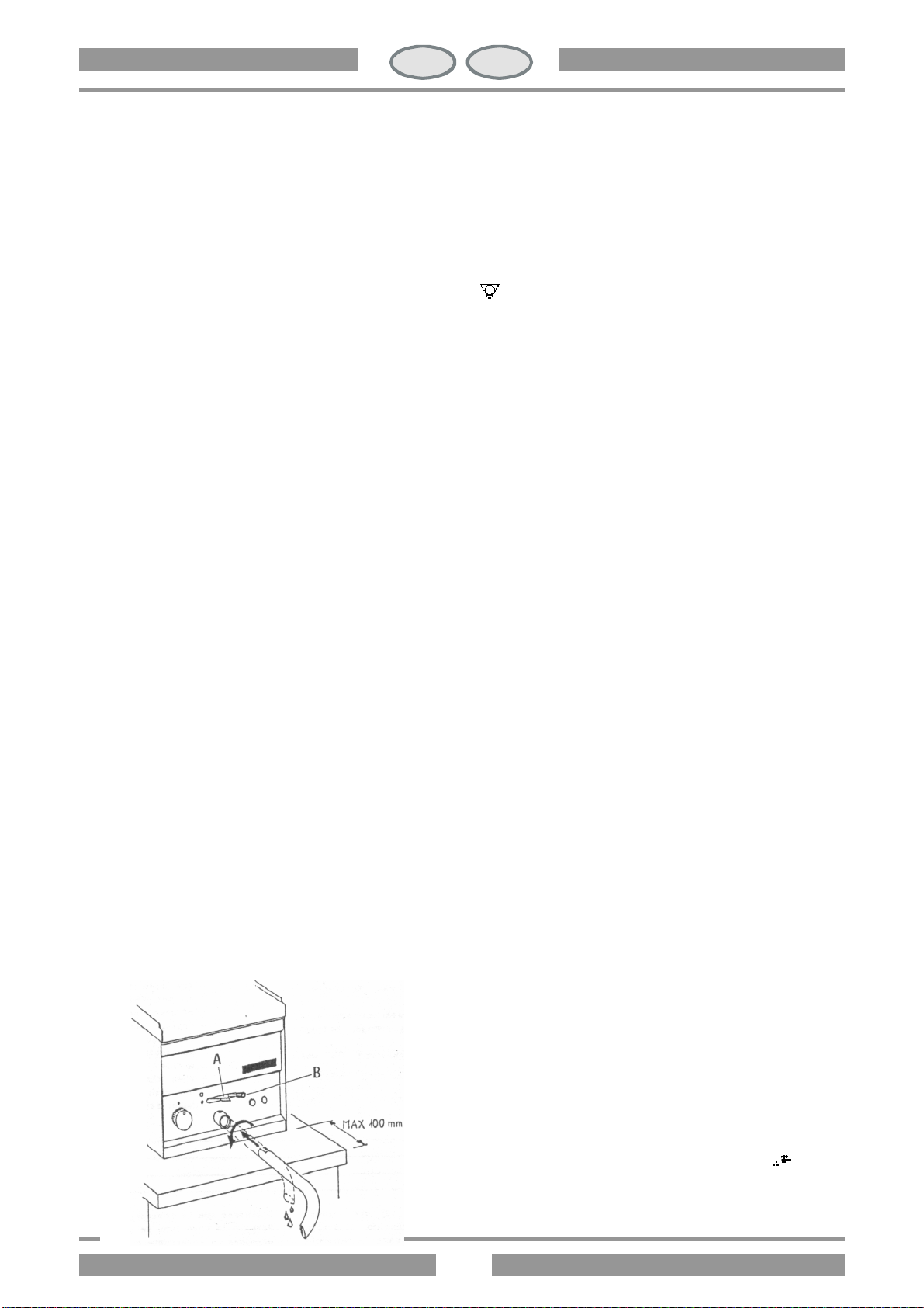
SVUOTAMENTO DELLA VASCA
L'utilizzatore è tenuto a munirsi di un contenitore adatto allo
svuotamento dell'olio. Questo contenitore deve essere di materiale
resistente al calore e deve essere costruito in modo che, durante lo
svuotamento, l'olio non tracimi e non rappresenti un pericolo.
Consigliamo di filtrare quotidianamente l'olio alla fine del lavoro e
di cambiarlo quando è necessario.
Inserire il tubo di scarico secondo il disegno, posizionare il
contenitore.
Spingere il dispositivo di sicurezza contro le aperture involontarie
(A) verso l'alto e portare la levetta (B) verso il simbolo
Importante: prestare attenzione alla distanza tra l'apparecchio e
gli spigoli del supporto.