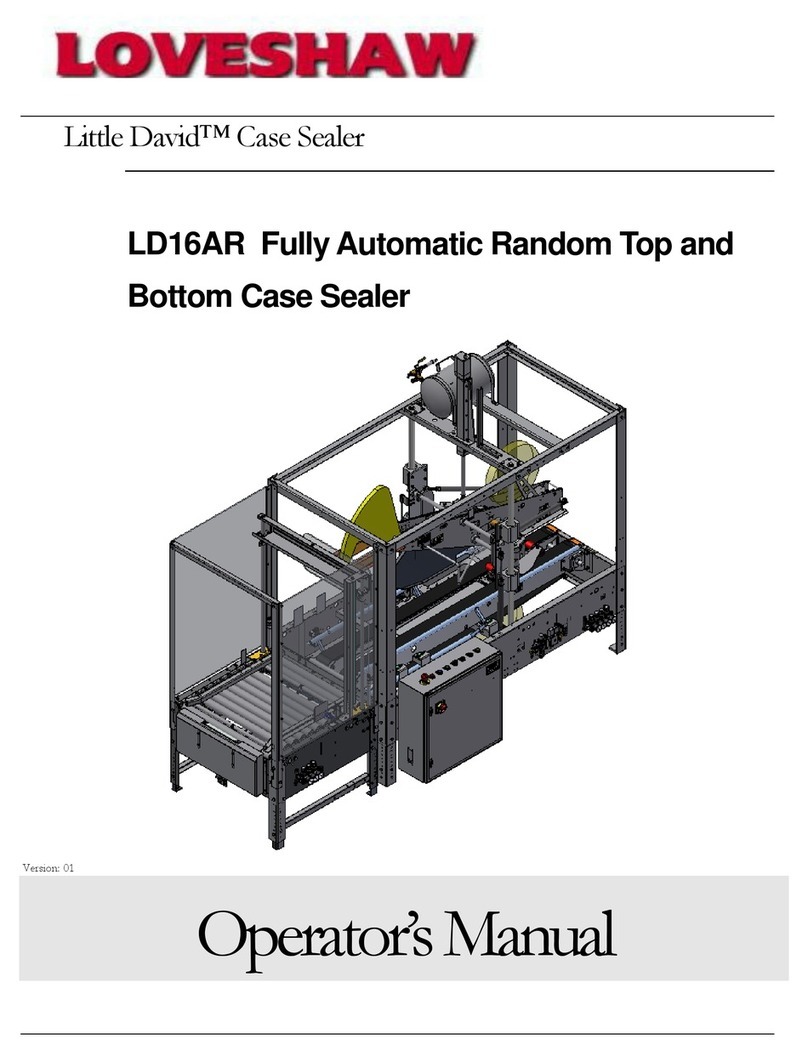
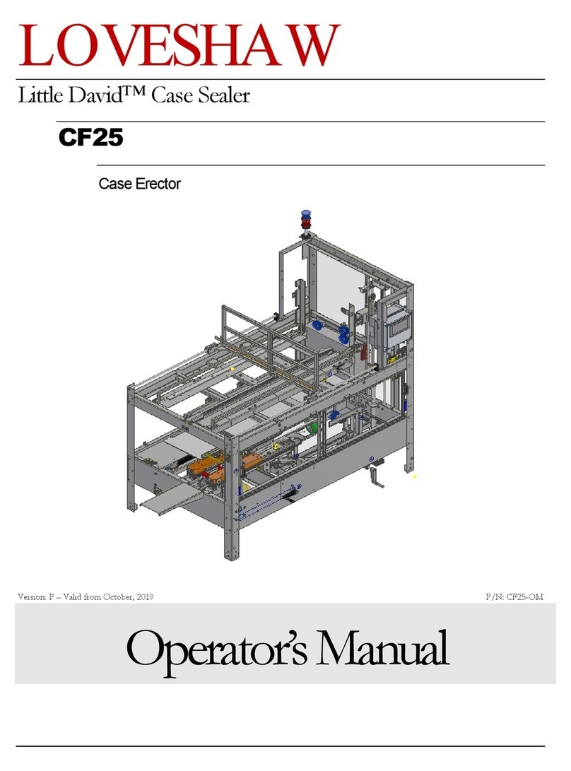
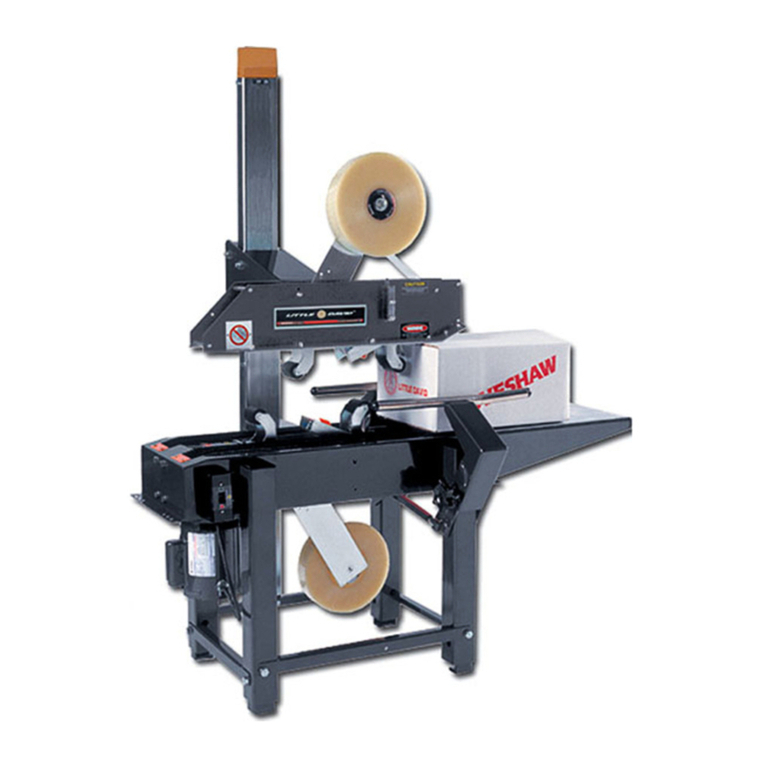
Loveshaw CASEFORM 40 User manual

OPERATION - MAINTENANCE - & PARTS MANUAL
MACHINE MODEL
CASEFORM 40
THE LOVESHAW CORPORATION
2206 EASTON TURNPIKE, BOX 83
SOUTH CANAAN, PA.
18459
TEL. (570) 937-4921
SEPT/05 M.C.R. #05-022

TABLE OF CONTENTS
SECTION #1 MACHINE SPECIFICATIONS
SECTION #2 INSTALLATION
SECTION #3 SEQUENCE OF OPERATIONS
SECTION #4 SIZE CHANGE-OVER
SECTION #5 START UP PROCEDURE
SECTION #6 SHUT DOWN PROCEDURE
SECTION #7 MAINTENANCE SCHEDULE
SECTION #8 HOW TO ORDER PARTS
SECTION #9 SPARE PARTS LIST
SECTION #10 TROUBLE SHOOTING
SECTION #11 ILLUSTRATED ASSEMBLIES

MACHINE SPECIFICATIONS
MACHINE MODEL: CASEFORM 40
SERIAL NUMBER: ????
STANDARD DISCHARGE HEIGHT: 23"
AMERICAN ELECTRICAL
REQUIREMENTS:
PRIMARY VOLTAGE:
CONTROL VOLTAGE:
EUROPEAN ELECTRICAL
REQUIREMENTS:
PRIMARY VOLTAGE:
CONTROL VOLTAGE:
110 VOLTS, 1 PHASE, 60 HERTZ
220 VOLTS, 1 PHASE, 50 HERTZ
CASE CAPACITY:
LENGTH:
WIDTH:
HEIGHT:
7" (178mm) MIN. TO 24" (609mm) MAX.
6" (152mm) MIN. TO 16" (406mm) MAX.
4" (102mm) MIN. TO 16" (406mm) MAX.
FLIGHT BAR SPEED: 85 FEET / PER / MIN.
MACHINE SPEED: UP TO 14 CASES PER / MIN.
CLOSURE MATERIAL: 2" OR 3" PRESSURE SENSITIVE TAPE
MAXIMUM ROLL DIAMETER: 15"
AIR REQUIREMENTS: 11 S.C.F.M. AT 14 CASES PER /MIN.
AT 80 PSI.
MACHINE OPTIONS:
1. LOW TAPE ALARM.
2. LOW HOPPER ALARM
3. CASTERS .
4. LEVELING PADS
5. EUROPEAN GUARDING

INSTALLATION PROCEDURE
Exercise care when handling this machine. a sudden jolt or jar may cause serious
damage.
Do not remove the shipping skid until machine has been moved to a point of
installation. The skid is designed for easy and safe handling of your machine.
Raise or lower the machine to the desired operating elevation using the leveling jack
screws and level the machine.
A great deal of trouble may be caused if the current is supplied by lines which are
not heavy enough. if this occurs, the motors and controls cannot operate at their full
capacity and over heating may result. A similar condition will exist if poor electrical
connections are made. It's therefore worthwhile to make sure that everything is
electrically correct.
Electrical polarity must be supplied to the machine exactly as shown on the electrical
diagram. Power must be supplied to L1 side of the circuit and the L2 side will be
neutral. If this is not correct, the circuit protectors (ECP 1) will trip out because of a
short circuit.
The air to the machine should be clean and dry, as the filter is only meant to remove
minor particles or slight amounts of moisture. Dirt or moisture in the air line can
cause the erratic operation of control valves.
Connect the air supply to an air source with a minimum line pressure of 80 PSI.
Before starting the machine, load the tape cartridge with tape and thread the tape.
See threading diagram on tape unit.
For proper start-up procedure see the start-up procedure section of this manual.

SEQUENCE OF OPERATION
INITIAL CONDITIONS:
A. MAIN AIR ON
B. POWER SWITCH OFF.
C. VACUUM CUP TROLLEY CYLINDER IS EXTENDED. (SOL. 5)
D. MINOR FLAP FOLDER CYLINDERS ARE RETRACTED. (SOL. 6)
E. CASE PUSHER CYLINDER IS RETRACTED. (SOL. 4)
F. VACUUM SWITCH IS ON.
GENERAL SEQUENCE:
1. Press the "START" push-button (PB 2). Motor contactor (M1) is energized and
the motor starts.
2. Normally open contact (M1) closes, programmable controller is energized, and
the sequence starts.
3. The case pusher and vacuum cup trolley go to home position.
4. As soon as proximity switches 2 and 3 are activated , the vacuum cup trolley
(output 102) moves forward to pick-up a blank.
5. At the extended position, the vacuum cup trolley activates proximity switch 1
(input 002) energizing timer 4. After a pre-set time, timer 4 times out, de-energizing
vacuum cup trolley solenoid (output 102).
6. The vacuum cup trolley then returns to the home position, activating proximity
switch 2 (input 003) energizing the minor bottom flap folders (output 104).
7. Proximity switch 2 energizes timer 3. After a preset time, timer 3 times out de-
energizing the vacuum solenoid (output 103). The formed case is released, ready
for case transfer.
8. As the chain lug is detected by photocell 1 (PC 1), the internal relay 1004 turns on
the case pusher solenoid (output 106), allowing the case pusher to move forward
and push the formed case towards the feed rollers, and then into the chain lug drive.

9. At the extended position of the case pusher, proximity switch 4 (Prox. 4) is
activated, energizing the internal relay 1003. This relay then de-energizes the case
pusher extend solenoid (output 106), sending the case pusher back to the home
position.
10. As output 106 is de-energized, timer 6 starts timing. When timer 6 times out, the
minor flap folder solenoid (output 104) is de-activated. The machine is now ready
for the next cycle.
11. Repeat sequence starting at general sequence #5.
NOTE 1: PC 2 is located downstream from the machine. During normal production,
this switch being closed, will signal the case pusher to push the next formed case
out of the forming area.
NOTE 2: SLS 1 and SLS 2 open when safety door is opened. The motor then
stops and all the air cylinders will loose air pressure. The safety doors must be
closed to re-start the machine.
NOTE 3: Pushing the cycle button on the hand-held control station or if contact with
the downstream photocell (PC 2) is made, will activate the machine to feed a case
into the taping section.
NOTE 4: All machine motions are pneumatically controlled from sequence
switching, which will not allow a defective case to be discharged from the machine.

CONTROL DESCRIPTION
SLS 1 SAFETY LIMIT SWITCH OPERATES WHEN SAFETY GATE IS
CLOSED.
SLS 2 SAFETY LIMIT SWITCH OPERATES WHEN SAFETY GATE IS
CLOSED.
PROX. 1 PROXIMITY SWITCH ACTIVATES WHEN TROLLEY IS HOME.
PROX. 2 PROXIMITY SWITCH ACTIVATES WHEN TROLLEY IS PICKING
BOX.
PROX. 3 PROXIMITY SWITCH ACTIVATES WHEN CASE PUSHER IS
RETRACTED.
PROX. 4 PROXIMITY SWITCH ACTIVATES WHEN CASE PUSHER IS
EXTENDED.
PROX. 5 BLANK HOPPER DRIVE SAFETY.
SOL 1 CONTROLS AIR SUPPLY TO SOLENOID VALVES.
SOL 2 CONTROLS VACUUM ON / OFF.
SOL 3 CONTROLS BLANK HOPPER DRIVE.
SOL 4 CONTROLS FORWARD MOVEMENT OF CASE PUSHER.
SOL 5 CONTROLS MOVEMENT OF TROLLEY.
SOL 6 CONTROLS MOVEMENT OF FLAP TUCKERS.
PC 1 SENSES CHAIN PUSHER LUG.
PC 2 CASE DEMAND SWITCH IS ACTIVATED WHEN THERE IS NO BOX
IN FRONT OF SENSOR.
PC 3 CYCLE START BUTTON.
SS 1 VACUUM OFF / ON SWITCH.

SIZE CHANGE OVER
NOTE:
TURN POWER OFF BEFORE MAKING ANY ADJUSTMENTS TO
THIS MACHINE.
HOPPER DRIVE ASSEMBLY
(C622922)
A. HOPPER WIDTH ADJUSTMENT:
TO SET, Loosen ratchet handle (item #19) and turn handknob (item #20) until the
blank that is about to be run fits loosely between the adjustable blank guide (item
#14) and the fixed side blank guide (item # 23).
Tighten ratchet handle before starting machine.
B. HOPPER BOTTOM FINGER ADJUSTMENT:
TO SET, The case bottom finger will need to be adjusted for almost every different
case size handled by the machine. This finger must be positioned in a manner as to
slip through the slots of the knock-down case at the manufacturers joint and slightly
hold the inside rear panel, as the vacuum cups pull the case from the hopper. This
finger aids in forming the knock-down case by breaking the case at the scoring.
Set the finger so that it is approximately 3/8" from the front face of the case and 1/4"
deep into the slot.
HOPPER FRAME ASSEMBLY
(C622920)
HOPPER HEIGHT ADJUSTMENT:
To adjust the hopper height rotate the handle on the top of the hydraulic pump (item
#10) clockwise for raising and anti-clockwise to lower.
You can set this adjustment using the scale on the side of the hydraulic cylinder
(item #6), divide the width of the case in 2, and set the pointer (item #21) to that
position on the scale.
When you are finished adjusting this assembly put the handle on the hydraulic pump
back into its locked position.
EXAMPLE: If the case you are running is 10" wide, you would set the pointer to 5"
on the scale.

FRONT FLAP FOLDER ASSEMBLY
(C622911-1)
There are no adjustments needed for the front flap folder assembly, other than
cylinder cushion adjustment, if required, and folder plate change parts.
REAR FLAP FOLDER ASSEMBLY
(C622264)
A. CASE PUSHER ASSEMBLY
TO SET, Loosen ratchet handles (item #10) and slide the rear flap folder assembly
until the pusher plate (item #9) is approximately a 1/4"away from the rear edge of the
formed carton, as it sits erected on the bottom flap folders.
You can set this adjustment using the scale on item #7.
Tighten ratchet handles before starting machine
EXAMPLE: If the case you are running is 16" long, you would set the pointer to 16"
on the scale.
B: REAR FLAP FOLDER ASSEMBLY
There are no adjustments needed for the rear flap folder, other than cylinder cushion
adjustment, if required, and folder plate change parts.
FORMING GUIDE ASSEMBLY
(C622277)
The forming guide assembly starts to fold the case end panel as the knock-down
case is pulled from the hopper, across the front face of the case pusher.
TO SET, Arrange the guide assembly so that a gradual transfer is obtained as the
knock-down case is pulled from the hopper across the forming guide, to the front of
the pusher plate. The forming guide assembly should be set so that the roller strikes
the center of the case.
Make sure to tighten all nuts and bolts on this assembly before starting machine.

TOP FINGER ASSEMBLY
(C622276)
TO SET, The case top finger will need to be adjusted for almost every different case
size handled by the machine. This finger must be positioned in a manner as to slip
through the slots of the knock-down case at the manufacturers joint and slightly hold
the inside rear panel, as the vacuum cups pull the case from the hopper. This finger
aids in forming the knock-down case by breaking the case at the scoring.
Set the finger so that it is approximately 3/8" from the front face of the case and 1/4"
deep into the slot.
VACUUM TROLLEY ASSEMBLY
(C622268)
A. CASE LENGTH ADJUSTMENT:
TO SET, Loosen ratchet handle (item #18) and slide the whole assembly across
until the center of the vacuum post (item #5) is centered on the center of the blank
length panel, or you can set this adjustment using the scale on the frame under the
U-channel (item #2), divide the length of the case in 2, and set the trolley assembly
to that position on the scale.
Tighten ratchet handle before starting machine.
EXAMPLE: If the case you are running is 16" long, you would set the vacuum cup
trolley to 8" on the scale.
B. CASE WIDTH ADJUSTMENT:
TO SET, Loosen ratchet handle (item #9) and slide the stop bracket (item #5) until
the center of the formed carton, as it sits erected on the bottom flap folders is always
at the center line of the machine. You can set this adjustment using the scale under
the stop bracket (item #5), divide the width of the case in 2, and set the back of the
stop bracket (item #5) to that position on the scale.
EXAMPLE: If the case you are running is 10" wide, you would set the stop bracket
to 5" on the scale.


BOX PUSHER ASSEMBLY:
A. Adjustment of the pusher assembly is attained only by loosening the two locking
levers on the side of the unit. Slide the front face of pusher plate to approximately
¼” back from the rear edge of the formed case, as it sits on the bottom folder plates
in their extended positions. adjust the pusher/folder to the desired case length
setting. Refer to the scale and the pointer.
B. See the folder plate change parts instructions.
C. Adjust the cylinder cushions, if required.
TOP GUIDES ASSEMBLY:
A. TOP GUIDE HEIGHT ADJUSTMENT:
Adjustment to the top guide is made by unlocking the locking lever and turning the
hand wheel until the top guide is approximately 1/16” above the top of the case flaps
of a fully formed carton at the discharge end of the machine. Use the scale on the
main frame for approximate measurement.
B. The carton top tensioner unit is used to hold and feed the cartons in the
magazine in an upright position.
VACUUM CUP ASSEMBLY:
A. There is really no specific formula for setting the configuration of the vacuum
cups on the case body. For small or extremely flimsy cases, the vacuum cups can
be set to pick up the top and bottom knock-down case flaps. Small cases will
require only two vacuum cups, while the larger cartons will require all four.
B. Position spring loaded vacuum cups as close as possible to the edge of the case
length panel to prevent cases from collapsing when pulled from the magazine.
C. When handling small cases (example 7” long), only two vacuum cups will be
required. Remove one of the vacuum cup bars and two of the vacuum cups.
Disconnect the two hoses using the quick release fittings which will automatically
seal off the vacuum system.
D. When handling a small height case, the vacuum post extension will need to be
changed.

VACUUM CUP ADJUSTING INSTRUCTIONS:
A. Although there is really no specific formula for setting the vacuum cup pattern on
your case, these few simple rules should be followed. The carton will open better
and stand less chance of collapsing, if the cups are positioned approximately ½”
from the case edge and ½” up and down from the top and bottom score lines.
B. Unless the case is less than 8” wide, then you will have to raise the lower
two vacuum cups to approximately 1 ¼” above the bottom score line to avoid
interference with the case pusher assembly.
C. Positioning the vacuum cups on the carton score line, is not best practice, but
in some cases it may be necessary.
CASE WIDTH ADJUSTMENT
Put a fully formed carton into the drive section at the discharge end. Loosen locking
lever and turn hand wheel until you have approximately 1/8” clearance on each side
of carton. Use the scale for approximate measurement.
BLANK HOPPER ASSEMBLY
A. When loading different length knocked-down cartons into the magazine,
remember the long side guide rail will have to be adjusted. The short rail side
never moves, this is your fixed point.
B. Adjustment to the case retainer bar and the brush will probably not be needed.
But if adjustment is desired, the round retainer rod right and brushes left, via the
adjustment slots. The rod and brushes slightly hold the cartons in an upright
position, as the vacuum cup assembly pulls the cartons from the magazine.
C. The case bottom opening finger will need to be adjusted for every different case
size handled by the machine. This finger must be positioned in a manner as to slip
through the slots of the knocked-down case at the manufacturers joint and slightly
hold the inside rear panel as the vacuum cups pull the cases from the magazine.
This finger aids in forming the knocked-down case by breaking case at the scoring.
D. Set finger so that it is approximately 3/8” from the front face of the case and ¼”
deep into the slot.
E. At the front of the case magazine, is located an elevation adjustment. This hand
wheel, when turned clockwise, raises the bottom score line of the knocked-down
case, and counterclockwise, lowers the score line.
F. The breaking point of the bottom leading and trailing case flaps, as the bottom
folder plates fold inner flaps upward, must remain the same on all cases as they
enter the forming section of the machine from the case magazine.

START UP PROCEDURE
THIS MACHINE IS TO BE USED, AS DESCRIBED, BY
PROPERLY TRAINED PERSONNEL.
WARNING:
NEVER.....START THE MACHINE UNTIL ALL PERSONNEL ARE CLEAR.
NEVER.....LUBRICATE OR REPAIR THE MACHINE WHILE IT IS RUNNING.
NEVER.....PUT YOUR HANDS IN THE MACHINE WHILE IT IS RUNNING.
NEVER.....ALLOW ANY PART OF YOUR BODY TO COME IN CONTACT WITH
MOVING PARTS OF THE MACHINE WHILE IT IS RUNNING.
1. CLOSE THE SAFETY DOORS.
2. LOAD BLANKS INTO THE HOPPER.
3. UNLATCH THE FEED BAR ON THE SLIDE HOPPER ASSEMBLY.
4. PRESS THE START BUTTON. (THE PUSHER LUGS ON THE CHAIN
DRIVE WILL START.)
5. TO TEST AND CYCLE THE MACHINE, TURN THE VACUUM SWITCH TO
OFF. PRESS THE CYCLE BUTTON. GO THROUGH THE CYCLE TWO OR
THREE TIMES TO MAKE SURE EVERYTHING IS RUNNING PROPERLY.
6. TURN THE VACUUM SWITCH TO ON. (THE MACHINE WILL START
FORMING CASES AND IT WILL STOP AUTOMATICALLY AS SOON AS
THE BOX IS IN FRONT OF THE CASE DEMAND PHOTOCELL.

SHUT DOWN PROCEDURE
EMERGENCY SHUT DOWN.
TO SHUT THE MACHINE DOWN IN AN EMERGENCY, PRESS THE STOP
BUTTON) ON THE HAND-HELD CONTROLLER.
NOTE: YOU WILL HAVE TO CLEAR ANY CASES THAT WERE BEING
FORMED BY THE MACHINE BEFORE YOU CAN RESTART THE MACHINE.
NORMAL SHUT DOWN.
1. TURN THE VACUUM SWITCH TO OFF.
2. LET THE MACHINE FINISH THE CYCLE OF CASES BEING FORMED.
3. PRESS THE STOP BUTTON ON THE HAND-HELD CONTROLLER.

MAINTENANCE SCHEDULE
TURN MACHINE OFF BEFORE PERFORMING ANY
MAINTENANCE.
ELECTRICAL
CHECK MONTHLY:
1. INSPECT FOR LOOSE WIRES THROUGHOUT THE MACHINE AND INSIDE
THE PANEL BOX.
2. INSPECT FOR MOISTURE INSIDE THE PANEL BOX.
3. CLEAN LENS ON PHOTOCELL.
PNEUMATIC
CHECK WEEKLY:
1. INSPECT AIR FILTER AND DRAIN IF NECESSARY. WATER IN THE AIR
LINES WILL CAUSE THE MACHINE TO ERRATICALLY CYCLE AND ALSO
GUM UP THE SOLENOID VALVES.
2. INSPECT AND CLEAR THE VACUUM GENERATORS.
3. INSPECT THE COMPONENTS AND THE AIR LINES FOR LEAKS. LOSS OF
AIR MEANS LOSS OF SPEED AND EFFICIENCY.
4. INSPECT THE VACUUM CUPS FOR CRACKS OR TEARS. (EVEN IF ONLY
(1) VACUUM CUP IS DAMAGED, TOTAL VACUUM WILL BE LOST FOR THE
COMPLETE SYSTEM.)
5. CHECK THAT VACUUM LINES ARE FREE FROM DEBRIS.
6. CHECK THAT REGULATOR IS SET TO 80 PSI.

CHECK MONTHLY:
1. INSPECT AIR CYLINDERS TO SEE THAT CUSHIONS ARE SET
PROPERLY.
2. INSPECT THE VACUUM HOSES FOR CRACKS OR CRIMPS.
MECHANICAL
1. INSPECT THE BOTTOM FLAP FOLDER ASSEMBLIES. CHECK FOR
BEARING WEAR. CHECK AIR CYLINDER MOUNTINGS FOR TIGHTNESS.
2. INSPECT ALL ADJUSTING SCREWS AND CHAINS THROUGHOUT THE
ENTIRE MACHINE. LUBRICATE ALL SCREWS AND CHAINS.
3. INSPECT THE CASE CARRIER CHAIN ASSEMBLY. CHECK FOR CHAIN
AND SPROCKET WEAR. LUBRICATE ALL BEARINGS, CHAINS AND
DRIVES.
4. INSPECT THE DRIVE UNIT ASSEMBLY. CHECK OIL LEVEL IN REDUCTION
AND LUBRICATE THE DRIVE CHAIN.
5. CHECK KNIFE FOR DEBRIS. CLEAN WITH OILY RAG. NEVER USE SHARP
OBJECTS TO CLEAN KNIFE.
NOTICE:
RIGHT ANGLE GEAR BOXES ARE PERMANENTLY LUBRICATED.

HOW TO ORDER SPARE PARTS
FOR GENERAL INFORMATION AND ORDERING PARTS CONTACT:
THE LOVESHAW CORPORATION
2206 EASTON TURNPIKE, BOX 83
SOUTH CANAAN, PA.
18459
TEL: 1-800-962-2633
It is necessary that before you contact Loveshaw for parts or service, that you know
the machine model and serial number.
Locate the label on the outside of the electrical panel box. You will see the machine
model and serial number printed on it.
WHEN CALLING LOVESHAW FOR PARTS:
A. Give the machine model and serial number.
B. Give the assembly part number and description.
(i.e., B570975 Major Flap Retainer Assembly.)
C. Give item number, part number and description.
(i.e., item #7, 204330, 1/2"I.D. x 5/8"O.D. Flange Bushing.)
By following the procedure described above, you will assist us in supplying you with
the correct parts for your machine and eliminate any mis-understanding between
your purchasing agent and our parts department.
See the list of suggested spare parts on the next page, by stocking these parts, you
will eliminate excessive down time waiting for shipment of parts.

CF40 2 INCH
RECOMMENDED SPARE PARTS KIT FOR
MODEL CF40 with CAC50 SIDE THREAD CARTRIDGE
KIT PART # .REPKIT-CF40
KIT LIST PRICE: $2600.00
PART # QTY DESCRIPTION LIST PRICE
.CAC50 1 TAPE CARTRIDGE $1050.00
A180584-P 2 WHEEL POLYURETHANE $171.60
PSC11B-4 4 KNIFE BLADE $100.00
200045 4 ROD END BEARING $167.84
200241 2 FLANGE BUSHING $7.34
200287 1 BUMPER $28.74
203220A 4 VACUUM CUP (BLUE) $88.12
201863 2 SPRING $4.88
202146 1 KNOB $6.12
202669 1 RACHET HANDLE $27.17
202822 1 SPRING $17.38
203169 2 TENSION SPRING $8.00
203214 2 THRUST WASHER $2.14
203354 1 BRUSH HOPPER 10” $44.82
A125SB-10-R 1 FUSE, 10 AMP $16.53
A125SB-2/10-312 1 FUSE, 2/10 AMP $6.21
402537A 1 REED SWITCH CYLINDER $60.24
303526 1 PHOTOELECTRIC SENSOR $74.36
400962 3 FLOW CONTROL VALVE $263.58
401118 1 SHOCK ABSORBER $221.94
402527A 1 VALVE $209.85
402317C 1 CASE PUSHER CYLINDER $275.50
402310C 1 TROLLY CYLINDER $333.17
302575 1 PROXIMITY SWITCH $111.36
TOTAL PURCHASED SEPARATELY $3296.89
KIT LIST PRICE: $2600.00
SAVINGS $696.89
www.loveshaw.com

CF40 3 INCH
RECOMMENDED SPARE PARTS KIT FOR
MODEL CF40 with CAC51 SIDE THREAD CARTRIDGE
KIT PART # .REPKIT-CF40/3
KIT LIST PRICE: $2800.00
PART # QTY DESCRIPTION LIST PRICE
.CAC51 1 TAPE CARTRIDGE $1375.00
A180584-P 2 WHEEL POLYURETHANE $171.60
PS4117A-4 4 KNIFE BLADE $120.00
200045 4 ROD END BEARING $167.84
200241 2 FLANGE BUSHING $7.34
200287 1 BUMPER $28.74
203220A 4 VACUUM CUP (BLUE) $88.12
201863 2 SPRING $4.88
202146 1 KNOB $6.12
202669 1 RACHET HANDLE $27.17
202822 1 SPRING $17.38
203169 2 TENSION SPRING $8.00
203214 2 THRUST WASHER $2.14
203354 1 BRUSH HOPPER 10” $44.82
A125SB-10-R 1 FUSE, 10 AMP $16.53
A125SB-2/10-312 1 FUSE, 2/10 AMP $6.21
402537A 1 REED SWITCH CYLINDER $60.24
303526 1 PHOTOELECTRIC SENSOR $74.36
400962 3 FLOW CONTROL VALVE $263.58
401118 1 SHOCK ABSORBER $221.94
402527A 1 VALVE $209.85
402317C 1 CASE PUSHER CYLINDER $275.50
402310C 1 TROLLY CYLINDER $333.17
302575 1 PROXIMITY SWITCH $111.36
TOTAL PURCHASED SEPARATELY $3641.89
KIT LIST PRICE: $2800.00
SAVINGS $841.89
www.loveshaw.com

TROUBLE SHOOTING
1. INSPECT WIRING FOR LOOSE CONNECTIONS.
2. INSPECT SIR LINES FOR LOOSE CONNECTIONS.
3. CHECK THAT PROXIMITY SWITCHES AND PHOTOCELLS ARE BEING
TRIPPED.
4. CHECK THE SAFETY GATE TO ENSURE THAT IT IS CLOSED.
PROBLEM SOLUTION
1. VACUUM SYSTEM IS NOT A. SOLENOID VALVE MAY BE DEFECTIVE.
OPERATIONAL. CHECK SOLENOID 2 FOR CONTINUITY.
REPLACE IF DEFECTIVE.
B. SPOOL IN VALVE MAY BE STUCK.
SQUIRT OIL IN VENT HOLE OF VALVE,
DISASSEMBLE VALVE. CLEAN
THOROUGHLY, REPLACE DEFECTIVE
PARTS. LUBRICATE AND REASSEMBLE.
C. CHECK THAT FLOW CONTROLS ARE
SET PROPERLY.
2. VACUUM TROLLEY WILL NOT A. SOLENOID VALVE MAY BE DEFECTIVE.
MOVE TOWARD BLANK MAGAZINE CHECK SOLENOID #3 FOR CONTINUITY.
TO PICK UP A BLANK. (CYLINDER REPLACE SOLENOID COIL IF DEFECTIVE.
IN RETRACTED POSITION.)
B. SPOOL IN VALVE MAY BE STUCK.
SQUIRT OIL IN VENT HOLE OF VALVE,
DISASSEMBLE VALVE. CLEAN
THOROUGHLY, REPLACE DEFECTIVE
PARTS. LUBRICATE AND REASSEMBLE.
C. PROXIMITY SWITCH (PROX 1) MAY
BE DEFECTIVE. CHECK CONTINUITY.
REPLACE IF DEFECTIVE.
Table of contents
Other Loveshaw Industrial Equipment manuals

Loveshaw
Loveshaw Little David LD16AR User manual

Loveshaw
Loveshaw LITTLE DAVID CAC51 User manual

Loveshaw
Loveshaw LITTLE DAVID CF5 User manual

Loveshaw
Loveshaw LD16AP User manual

Loveshaw
Loveshaw LITTLE DAVID LD7D/3 Parts list manual

Loveshaw
Loveshaw Little David CF25 User manual

Loveshaw
Loveshaw LITTLE DAVID CAC60 Series User manual
Popular Industrial Equipment manuals by other brands

riverhawk
riverhawk IM-116 instruction manual

HBK
HBK RTN Mounting instructions

Roper Whitney
Roper Whitney PEXTO PX-24 Operating instructions and parts identification

schmersal
schmersal AZM300Z-ST-1P2P-N manual

Safeway
Safeway VHV-200V instruction manual

Oshkosh Corporation
Oshkosh Corporation JERR-DAN HDR 70/85-530 Operation and maintenance manual