LS ELECTRIC H100 2(PLUS) Series User manual

This operation manual is intended for users with basic knowledge of electricity and electric
devices.
* LSLV-H100+ is the official name for the H100+ series inverters.
* The H100+series software maybe updated without prior notice for better performance.To
check the latestsoftware, visit our websiteat http://www.ls-electric.com.

Quick Start Reference
Q
ii
Quick Start Reference
This chapter provides details on product identification, part names, correct installation and cable
specifications. To install the inverter correctly and safely, carefully read and follow the instructions.
Verify & Identify the delivery
Verifythat you have ordered andreceived thecorrect VFD by checking the nameplateinformation.
Utilize the example name plate below to assist you with this.
Mounting Instruction
Ensure that there is sufficient space to meet the clearance specifications, and that there are no
obstacles impeding the cooling fan’s air flow as shown below.
Wheninstalling multiple drives into the same enclosure panel (Side-by-side installation), mount the
drives with the minimum clearance of 2 mm while removing optional top covers.
<installation space>
<Mounting precaution>
Install the drive in an environment that meets the conditions such as ambient temperature (-10℃
to 50℃), humidity(95% relative humidity or free of condensation), altitude (below 1,000m) and
vibration(below 1G [9.8 m/sec2])

iii
Quick Start Reference
After mounting, and in order to move onto the wiring step, loosen thecaptive screw on the terminal
cover. Squeeze the tabs and “hinge off” the cover. Squeeze tabs and slide up the wire guide to
expose the power terminals. This wire guide can be disposed of if you have purchased a NEMA1
conduit kit. For the larger H100’s remove the screws securing the metal cover.
0.75–90 kW Models 110–185 kW Models 220–500 kW Models
Wiring the VFD : Power
The following figures show main circuit terminal arrangement on the drive.
WARNING! B1, B2 terminals are for the brake resistor. Do not connect B1, B2 terminals to earth
ground.
WARNING! Power supplycables must be connected to R, S and T terminals. Connecting power
cables to the U, V, and W terminals will cause internal damage to the drive.
<Single Phase Input H100> <Three Phase Input H100>

Quick Start Reference
Q
iv
Wiring the VFD : Control
The figures below show the control circuit terminal arrangement on the drive.
Switch
Description
SW1
Terminating Resistor
(Left: On, Right: Off)
SW2
Left: PNP, Right: NPN
SW3
Left: V1, Right:T1(PTC)
SW4
analog input (Left: I2, Right: V2)
SW5
analog output (Left: VO, Right: IO)

v
Quick Start Reference
Function
Label
Name
Description
Multi-function
terminal
configuration
P1–P7
Multi-function Input 1-7
P1: Fx (IN-65)
P2: Rx (IN-66)
P3: BX (IN-67)
P4: RST(IN-68)
P5: Speed-L (IN-69)
P6: Speed-M (IN-70)
P7: Speed-H (IN-71)
CM
Common terminal
Analoginput
configuration
VR
Potentiometer powersupply
Maximum Voltage Output: 12 V
Maximum Current Output: 12mA
Potentiometer : 1–10k Ω
V1
Voltage input forfrequency
reference
Unipolar: 0–10 V(12V Max)
Bipolar: -10–10 V(±12V Max)
V2/I2
Voltage/current input for
frequency referenceinput
Input current: 0–20 mA
Maximum Input current: 24 mA
Input resistance 249 Ω
TI
Pulse input for frequency
reference input (pulse train)
Setupormodifyfrequencyreferences using
pulseinputs from 0 to 32 kHz.
LowLevel:0–0.8 V, High Level: 3.5–12 V
Function
Label
Name
Description
Analog
output
AO
Voltage/Current
Output
Output voltage: 0–10 V
Maximum output voltage/current: 12 V/10 mA
Output current: 0–20mA
Maximum output current: 24mA
Factorydefaultoutput:Frequency
Terminal
Contacts
Q1
Multi-function (Open
Collector) Pulse
Output
DC 26 V, 50 mAorless
Pulse output terminal
Output frequency: 0–32kHz
Output voltage: 0–12 V
EG
Common ground
Common ground contact for an open collector
24
24 V power supply
Maximum output current: 100 mA
A1/C1/B1
Fault relayoutput
A,B contact
N.O.:AC250V ≤2 A, DC 30 V ≤3A
N.C.:AC250 V ≤1A, DC 30 V ≤1A
A2/C2-
A5/C5
Multi-function relay
outputAcontact
AC 250 V≤5A, DC 30 V≤5A
S+/S-/SG
RS-485 signal line

Quick Start Reference
Q
vi
Keypad: Description
Key
Name
Description
[MODE] Key
Used to switch between modes.
[PROG/ ENT] Key
Used to select, confirm, or save a parameter value.
[Up] [Down] key
Switchbetween codes or increase or decrease parameter values.
[Left] [Right] key
Switchbetween groups or move the cursor during parameter setup
or modification.
[RESET/ MULTI]
Key
Used to perform special functions, such as user code registration.
(Factory Default Value –RESETfunction)
[ESC] Key
Used to cancel an input during parametersetup.
[HAND] Key
Used to switch to HAND (local/manual) operationmode.
[OFF] Key
Used to switch to OFF (standby) mode or to reset the inverter
faults.
[AUTO] Key
Used to switchtoAUTO(remote) operation mode.
HAND LED
Turns on green (steady) during HAND mode operation.
OFF LED
Turns on red (steady) while the inverteris in OFF mode (standby),
and flashes then a fault trip occurs. The LED turns on red (steady)
again when thefault trip condition is released.
AUTOLED
Turns on green (steady) when the inverteroperates inAutomode,
and flashes green when the inverteris inAUTO mode, but is not
operating.

vii
Quick Start Reference
Keypad Navigation and Parameter Changes
Navigate and select different parameters by using the directional arrows on the keypad while in the
PAR Mode.
From the main screen, the [MODE] key will change the keypad to display the Parameter (PAR)
mode.The PARmode contains all parameters and monitors. These parameters and monitors are
divided into intuitive groups. Pressing the LEFT or RIGHTarrows will move through the different
parameter groups.While the UP and DOWN arrows will navigate throughthe differentparameter
code #’s in the selected group.
Any of the above parameters settings can be changed by pressing the [PROG/ENT] key, selecting
the new setting with the arrows, and pressing [PROG/ENT] again to save.

Quick Start Reference
Q
viii
Verify Motor Direction
This step explains how to check motor direction by running the motor at a low speed via the
keypad in HAND mode. Verify that the power and motor wiring matches the previous step and
covers are installed before applying power.
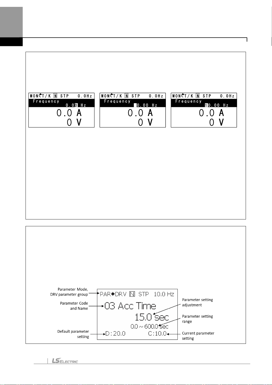
At first power up, the display will look like below. “0.0 Hz” represents the default HAND frequency
reference.
Checking Direction
Use the above mentioned steps to run the motor in the forward direction in HAND mode. The
displaywill brieflyshow the output frequencyof the VFD until it reaches 10Hz.
Look at the motor shaft to verify rotation is correct. Press the OFF key to STOP.
If motor direction is incorrect, stop the motor with the OFF key, and power down the VFD.
Wait at least 5 minutes to let the VFD capacitors discharge.
Swap anytwo output leads between the VFD and the motor. This will change motor direction.
Verifycorrect rotation via the previous steps.
Changing Acceleration Time - Example
1. Press the [MODE] key from the main display to access PAR Mode.
2. In the DRV group, press down to select DRV 03 (Acc Time).
3. Press the [PROG/ENT] key access the current setting.
4. Use the UPand DOWN arrows to increase and decrease the value.
5. Use the LEFT or RIGHT arrows to move the cursor over to select different digits.
6. Press the [PROG/ENT] key once the desired value is set. This saves the change.
7. DRV 03 will be displayed again indicating the parameter change has taken effect with the new
value displayed.
Press LEFT arrow 3
times so that the cursor is
flashing to the left of
“0.00”.
Press UP arrow so that 10.00
is displayed.
Press the Hand keyto run the
motor in the forward direction.

ix
Quick Start Reference
HAND / AUTO / OFF keys
The H100+ series inverters have two operation modes–the HAND andAUTO modes. HAND
mode is used for local control using the keypad.AUTO mode is used for remote controlusing the
terminal inputs or networks commands (thekeypad maystill be used inAUTO mode if the
command source is set as ‘keypad’).
DRV-08:Auto Mode Selection (AUTO Mode Sel)
1) DRV-08 = 0 (Enabled)
If [DRV-08 AUTO Mode Sel] is set to “0 (Enabled)”, the inverter starts to operate only when the
operation command is input inAUTO mode.
2) DRV-08 = 1 (Disabled) –Factory default
If [DRV-08 AUTO Mode Sel] is set to “1 (Disabled)”, the inverter automatically switches toAUTO
mode and starts to operate when the operation command is input regardless of inverter’s state of
being inAUTO or OFFmode.

Quick Start Reference
Q
x
Codes / Functions
Description
DRV-01
Cmd Frequency
Frequency referenceinAUTO mode when DRV-07 is set to’ KeyPad’.
DRV-02
KeyPad Run Dir
Rotation direction of thekeypad commandin the HAND orAUTO mode.
Settings
Description
0
Forward
Fxoperation
1
Reverse
Rxoperation
DRV-05
KPDH.O.ALock
To make HAND-OFF-AUTO enabled/disabled
Settings
Description
0
Locked
To make HAND-OFF-AUTO disabled andturnAuto mode
1
During
Run
If [DRV-06 cmd source] is Fx/Rx-1, Fx/Rx-2, int485 or
fieldbus, Hand-off-auto is enabled only when Off
2
OFF Key
Enable
UnderthesameconditionsasDuringRun,onlytheOFF
key is activated. (Factory Default)
3
Unlocked
To make HAND-OFF-AUTO enabled
DRV-08AUTO
Mode Sel
Set whether touseAUTO mode.
0. Enabled
1. Disabled (Factorydefault)
DRV-24 Hand Key
Sel
This functionenables/disables theHAND key on the keypad.
Settings
Description
0
None
Followthe settings of [DRV-05KPDH.O.ALock].
1
Disabled
Regardless of the setting of [DRV-05 KPD H.O.ALock],the
HAND key is disabled.
DRV-25
HAND Cmd Freq
Frequency displayedat the monitor display item (Monitor Line-1) when the HAND
key is pressed in other modes (default frequency reference for HAND mode).
DRV-26
Hand Ref Mode
Set Hand frequency reference source (Typically Drive Keypad).
0. Hand Parameter
1. V1
2. V2
3. V3
4. I2
5. I3
6. FollowAuto
OUT-31–36
Relay1–5
SetAUTO State (36) to ensurethatthe inverter is inAUTO mode.
OUT-31–36
Relay1–5
Set HAND State (37) to ensure that the inverter isin HAND mode.

xi
Quick Start Reference
Control Wiring
This stepshows common wiringexamples for both the run command andfrequencyreference
when operating inAUTO Mode. However, when DRV-08 Auto Mode Sel is set to “1. Disabled”
(Factory default), it’s available to operate without trasffering to “AUTO Mode”.
2-Wire Control
2-wire control consists of maintained run signals. This can be accomplished via toggle switches,
relays, jumpers, etc. Default parameters support this operation.
Speed POT Wiring (0-10VDC)
Controlling the VFD with an external speed POT can be accomplished bysetting DRV7=2 V1
and wiring like below. For 0-10VDC signals from a BAS or Controller simplywire to V1 and CM.
BAS or Controller Wiring (4-20mA)
For speed control over a 4-20mAsignal set DRV7=5. I2.
Important: Verify that SW4 dip
switch on the terminal board to ‘I2’
(LEFT) for 4-20mA signal.

Quick Start Reference
Q
xii
EZ Start
This Stepprovides details on EZ startsteps.
Step
Parameter
Description
1
CNF-43: Select a macro.
0. Basic (Default)
1. Pressure Ctrl
2. Lead-Lag
2
DRV32: Regional Set
0. US
1. International
2. KR
3
AP3-01 Now Date
Set Date
4
AP3-02 Now Time
SetTime
5
DRV-14 Motor Capacity
Set HP rating
6
BAS-10 60/50 HzSel
Setmotor rated frequency
7
BAS-13 Rated Curr
Setmotor rated current
8
BAS-15 Rated Volt
Setmotor rated voltage
9
BAS-11 Pole Number
Setmotor polenumber.
10
BAS-19ACInputVolt
Set input voltage.
11
DRV-06 Cmd Source
Cmd Source: Set command source.
12
DRV-07 Freq Ref Src
Set Frequency Reference source.
13
DRV-03AccelTime
Sets the time to accelerate from 0to maximum frequency
14
DRV-04 Decel Time
Sets the time to decelerate from maximumfrequency to 0.
15
ADV-08 Stop mode
Stopping Method
0. Decel stop
1. DC-Brake
2. Coast stop
4. Power Braking
16
ADV-09 Run Prevent
Choose a direction to prevent
1. Forward Prev
2. Reverse Prev
17
PRT-05 Phase loss check
When open-phase protection is operating, input and output
configurations are displayed differently. When the LCD segment
is On, the corresponding bit is set to ‘Off’.
Setting
Function
Bit 1
Bit 0
√
Output open-phase protection
√
Input open-phase protection

xiii
Quick Start Reference
Step
Parameter
Description
18
PRT-08 Select start at trip
reset
Select start at trip reset
Setting
Function
Bit
7
Bit
6
Bit
5
Bit
4
Bit
3
Bit
2
Bit
1
Bit
0
√
Standard Trips
except the below
√
Low Voltage Trip
√
Low Feedback
Trip
√
High Feedback
Trip
√
SetPoint Timeout
√
Overcycle Trip
√
High Flow Trip
√
Accum Flow Trip
19
PRT-09 Retry Number
Sets the number of restart trial when performing a tripreset.
20
PRT-20 OLTrip Select
0. None
1. Trip & Coast
2. Decel Stop
21
PRT-21 OLTrip Level
When the current supplied to the motor is greater than the preset
value of the overload trip level (OL Trip Level) and continues to
be supplied during the overload trip time (OL Trip Time), the
inverter output is either blocked according to the preset mode
from PRT-17 or slows to a stop after deceleration.
22
PRT-22 OLTrip Time
23
PRT-40 ETH Trip Sel
0. None
1. Trip & Coast
2. Decel Stop
24
PRT-41 Motor Cooling
0. Self-cool
1. Forced-cool
25
PRT-42 ETH 1 min
The amount of input current that can be continuously supplied to the
motorfor 1 minute,based on the motor-rated current (BAS-13).
26
PRT-43 ETH Cont
Sets the amount of current with theETH function activated. The range
belowdetails the set values that canbe used during continuous
operation without the protection function

Quick Start Reference
Q
xiv
Basic Setup
The basic drive and motor parameters are shown on the below table. Set the parameters according
to your specific application.
1. Motor Parameters
Set the below motor parameters based on the motor nameplate.
Group
No
Description
Default
Set Options
DRV
14
Motor Capacity
Depends on drive
Depends on drive
BAS
11
Poles
4
2 - 12
BAS
13
Motor Rated Current
Depends on drive
Depends on drive
BAS
15
Motor Voltage
Depends on drive
Depends on drive
▶Motor RPM to Poles chart
RPM
3600
1800
1200
Poles
2
4
6
▶Example:
If actual motor RPM is 3450, Set Motor Poles = 2. This is due to motor slip. In this example, the
motor has 150 RPM of slip. (Slip=Synchronous speed-Rated Speed)
2. Commonly Set Parameters
Group
No
Description
Default
Set Options
DRV
1
Command Freq
0.00
0 –MaxFreq
DRV
3
AccTime
20
0 –6000
DRV
4
DecTime
30
1 –6000
DRV
6
Run Command
1. Fx/Rx - 1
0. Keypad
1. Fx/Rx - 1
2. Fx/Rx - 2
3. Comm RS485
4. Field Bus
DRV
7
Freq Command
0. Keypad - 1
0. Keypad - 1
1. Keypad - 2
2. V1
4. V2
5. I2
6. Comm RS485
8. Field Bus
12. Pulse
BAS
19
Input Voltage
240/480
170 –480V
3. Optional Parameters
To automatically start after a power loss, setADV 10=Yes.
Enable phase loss protection by setting the dipswitches in PRT 05 both up.

xv
Quick Start Reference
Application Setup
This step shows how to set the pressure control.
1. Activate PID function
▶PID-01 PID Sel
To enable PID operation, set [PID-01 PID Sel] to“Yes”
▶PID-02 PID Access Lev
The Default Value for [PID-02 PIDAccess Lev] only allows access to the basic parameters in the
PID group. The rest are hidden. When set to “Adanced”, all paramters are shown.
2. Unit Scaling
▶PID-50 PID Unit Sel
Setting
0
CUST
14
I
28
kg/h
1
%
15
kW
29
gl/s
2
PSI
16
HP
30
gl/m
3
˚F
17
mpm
31
gl/h
4
˚C
18
ft
32
ft/s
5
inWC
19
m/s
33
f3/s(ft3/min)
6
inM
20
m3/s(m 3/S)
34
f3/h (ft3/h)
7
Bar
21
m 3/m(m 3/min)
35
lb/s
8
mBar
22
m 3/h(m 3/h)
36
lb/m
9
Pa
23
l/s
37
lb/m
10
kPa
24
l/m
38
lb/h
11
Hz
25
l/h
39
ppm
12
Rpm
26
kg/s
40
pps
13
V
27
kg/m
41
Wb
14
I
29
gl/s
▶PID-51 PID Unit Scale
Adjusts the scale to fit the unit selected at PID-50 PID Unit Sel.
▶PID-52, 53 PID Unit 0 %, 100 %
Sets the Unit 0% and Unit 100% values as the minimum and maximum values set at
PID-50.

Quick Start Reference
Q
xvi
3. Setpoint, Feedback Scaling
▶PID-10 PID Setpoint 1 Source
Setting
0
Keypad
6
FieldBus
1
V1
7
-
2
-
8
Pulse
3
V2
9
V3
4
I2
10
I3
5
Int485
▶PID-11 PID Setpoint 1 Set
A setpoint value can be entered if the PID setpoint source (PID-10) is set to ‘0 (Keypad)’. And also
PID setpoint can be set in Monitorscreen when PID-10 is setto ‘0 (Keypad)’.
▶PID-20 PID Fdb Source
Setting
0
V1
5
FieldBus
1
-
6
-
2
V2
7
Pulse
3
I2
8
V3
4
Int485
9
I3
4. Sleep Mode
▶PID-59 Sleep Level type
The following sleep level types can be selected:
Setting
1
Frequency(FactoryDefault)
2
Output Current
3
PID Feedback Value
4
RPM
5
Flow Rate
▶PID-62 PID Sleep 0 DT
▶PID-63 PID Sleep 0 Lev
If the operating frequency stays below the frequencies set at PID-63 for the set times at
PID-62, the VFD enters standby mode.
▶PID-56 Pump Minimum Speed
Pump minimum speed sets the low limit on the command frequency.Minimum Limit
operates based on the greatest value of following:
-AP2 40 Thrust Frequency, PID 56 Pump Minimum Speed, ADV 25 Freq Limit Lo

xvii
Quick Start Reference
4. Wakeup level
▶PID-57 WakeUpLev type
0.Absolute or 1. Deviation (Factorydefault) can be selected for the Wake-up level
Feedback
Wakeup
Delay time Deviation
Absolute
Wakeup Level
=Set point-wakeup level
Setpoint
▶PID-64 PID WakeUp 0 DT
▶PID-65 PID WakeUp 0Lev
Sets the reference for PID operation in PID sleep mode. PID operation resumes when PID
feedback variation (from the PID reference) exceeds the values set in PID-65 for more than the
time set in PID-64.
5. Lost Feedback Detection Mode
Lost Feedback Detection shuts down the pump system when the feedback device failed.
The set values in [PRT-14] and [PRT-15] of frequencycommand parameters are also used for the
operation of Lost Feedback DetectionTime and Lost Feedback Preset Frequency
▶AP2-75 LostFbkMode
Setting
0
None
1
Warning
2
Trip & Coast
3
Lost Preset
▶PRT-14 Lost Cmd Time
▶PRT-15 Lost Preset Frequency

Quick Start Reference
Q
xviii
6. High/Low Feedback Detection
Low/High feedback detection detects whether PID feedback is higher than high feedback level or
lower than low feedback level to trigger Warning or Trip&Coaststop.
▶AP2-48 High Feedback Detection Mode
▶AP2-49 High Feedback Level Fault Delay Time
▶AP2-50 High Feedback Level
PID
Feedback
Output
Freq.
High Fdb
Digital
Output
High Fdb
Trip
High
Fdb lvl
Hysteresis
High Fdb
Time
High Fdb
Time
▶AP2-51 Low Feedback Mode
▶AP2-52 Low Feedback Level Fault Delay Time
▶AP2-53 Low Feedback Level
▶AP2-54 Hysteresis Level
PID
Feedback
Output
Freq.
Low Fdb
Digital
Output
Low Fdb
Trip
Low
Fdb
level
Low Fdb
Time Low Fdb
Time
Hysteresis

xix
Quick Start Reference
7. Thrust Bearing Control
Thrurst Bearing Control function changes acceleration and deceleration time based on a certain
frequency in order to protect the bearing of the submersible pump.
▶AP2-40 Thrust Frequency
▶AP2-41 Thrust BearingAcceleration Time
▶AP2-42 Thrust Bearing Deceleration Time
Output
Frequency
Thru st Operation Hand/Auto Operation
Thru st Frequency
Thrust Acc Time

Quick Start Reference
Q
xx
Macro –Pressure Control (MC1) Group
Macro
Code
Code
LCD
Display
Initial Value
Macro
Code
Code
LCD
Display
Initial Value
0
-
Jump
Code
1: CODE
1
DRV-
3
AccTime
0.75~9
0kW
10.0
110~25
0kW
30.0
315~50
0kW
50.0
2
DRV-
4
Dec
Time
0.75~90
kW
20.0
3
DRV-
6
Cmd
Source
1: Fx/Rx-1
110~25
0kW
60.0
315~50
0kW
100.0
4
DRV-
7
Freq Ref
Src
0: Keypad-1
5
DRV-
24
Hand Key
Sel
0. None
6
ADV-
8
Stop
Mode
-
7
DRV-
14
Motor
Capacity
-
8
BAS-
10
60/50 Hz
Sel
-
9
BAS-
11
Pole
Number
-
10
BAS-
12
Rated
Slip
-
11
BAS-
13
Rated
Curr
-
12
BAS-
15
Motor
Volt
1:Yes
13
ADV-
9
Run
Prevent
2. Reverse Prev
14
ADV-
64
Fan
Control
2. Temp Control
15
PID-1
PID Sel
1:Yes
16
PID-
10
PID SP 1
Src
0. Keypad
17
PID-
11
PID SP 1
Set
18
PID-
20
PID Fdb
Source
3. I2
19
PID-
25
PID P-
Gain 1
-
20
PID-
26
PID I-
Time 1
-
21
PID-
36
PID Out
Inv
0. No
22
PID-
50
PID Unit
Sel
2. PSI
23
PID-
51
PID Unit
Scale
1.x 10
24
PID-
PID Unit
100.0
25
PID-
RampPIRe
0. No
This manual suits for next models
11
Table of contents
Other LS ELECTRIC DC Drive manuals
Popular DC Drive manuals by other brands

Danfoss
Danfoss vlt aqua Programming guide

Masterflex
Masterflex L/S MFLX07528-10 operating manual

Danfoss
Danfoss VLT 5000 Series manual

Chauvet DJ
Chauvet DJ Vivid Drive 23N Quick reference guide

diytube
diytube Poseidon Driver Instructions for assembly and operation

Toshiba
Toshiba ACE-tronics G9 ASD Installation and operation manual

Allen-Bradley
Allen-Bradley Rockwell Automation PowerFlex 700 Series Original instructions

D+H
D+H CDC-TW-0502-0350-1-ACB Original instructions

Festo
Festo EMCS-ST operating instructions

Aumuller
Aumuller FVUI Assembly and commissioning instructions

GE
GE Fuji Electric MICRO-SAVER AF-300 instructions

GE
GE Fuji Electric AF-300ES instructions