LS ELECTRIC H100 Series User manual

3-phase 200~240V 0.75~18.5kW
3-phase 380~480V 0.75~500kW
Fan and Pump Drive
H100

The LSLV-H100 sets the standard for the drive industry.
Environmentally friendly water treatment and Fan and Pump
systems incorporate the outstanding energy-saving benefits of the
LSLV-H100 for fans and pumps.
Innovative Energy Reduction:
The LS H100 drive solution is here for you.
02_ LS ELECTRIC

Scan the QR code on your drive front and
check the key use information
!
Fan and Pump Drive
•Communication Module Exclusive
for Fan and Pump-BACnet
•Global Specifications
Compliant-UL Plenum Rated
•Soft Fill Control
•Multiple-motor Control
•Fire Mode
•Side-by-Side Installation
•Reduced Size
H100 _ 03
Maximized User
Convenience
Efficient Use of Space
Stable System Control
-4-7)'FBUVSFT
.PEFMBOE5ZQF
4QFDJDBUJPOT
5FSNJOBM$POHVSBUJPO
'VODUJPO$PEFT
%JNFOTJPOT
'VTF3FBDUPS
Contents

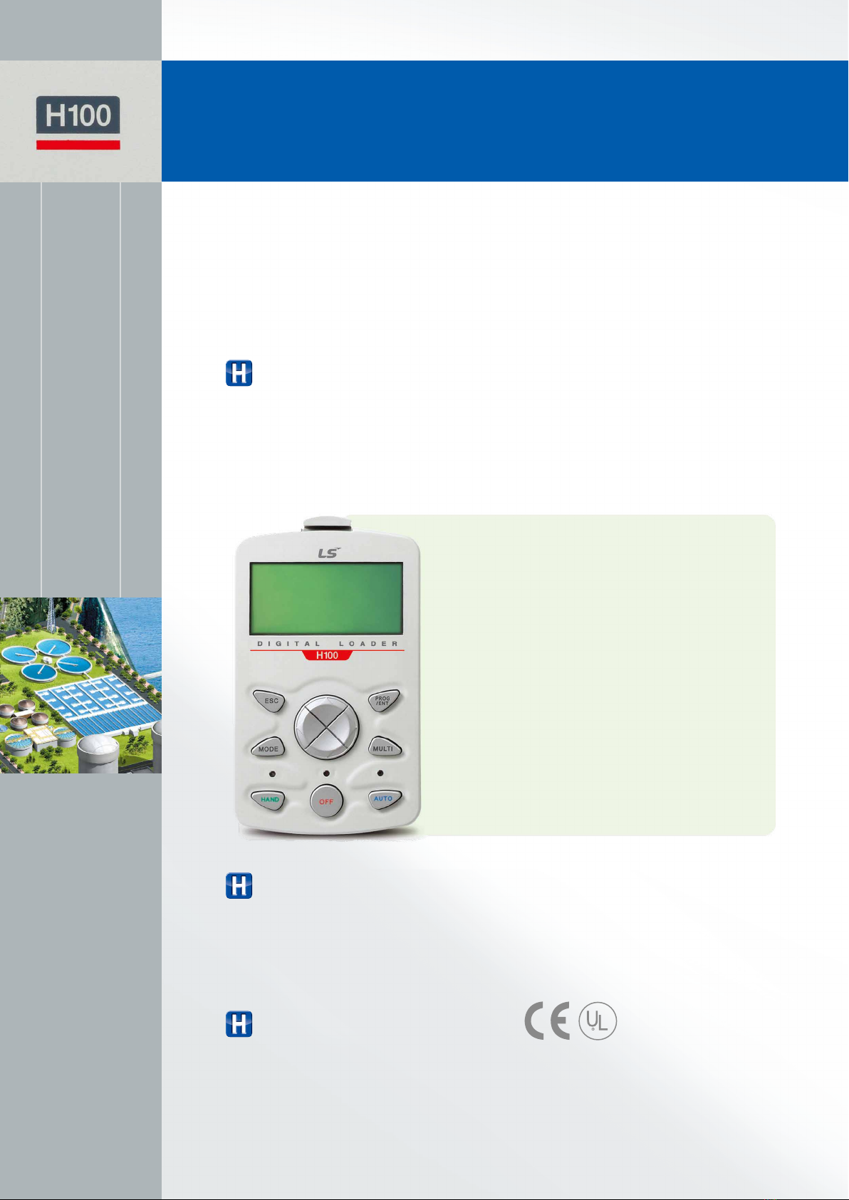
LSLV-H100 drives include a user-friendly keypad
designed exclusively for the Fan and Pump market
and satisfy various needs of customers.
Maximized User Convenience
Used to issue commands, configure drive parameters, and for monitoring drive status
•HAND Mode (Local Control Mode) or AUTO Mode (Remote Control Mode) can be selected.
- HAND Mode: Used when selecting frequency or run/stop commands.
- AUTO Mode: Drive operated using the keypad, multifunctional terminal block and
communications.
•Fault Status Monitoring
Keypad Exclusive for Fan and Pump
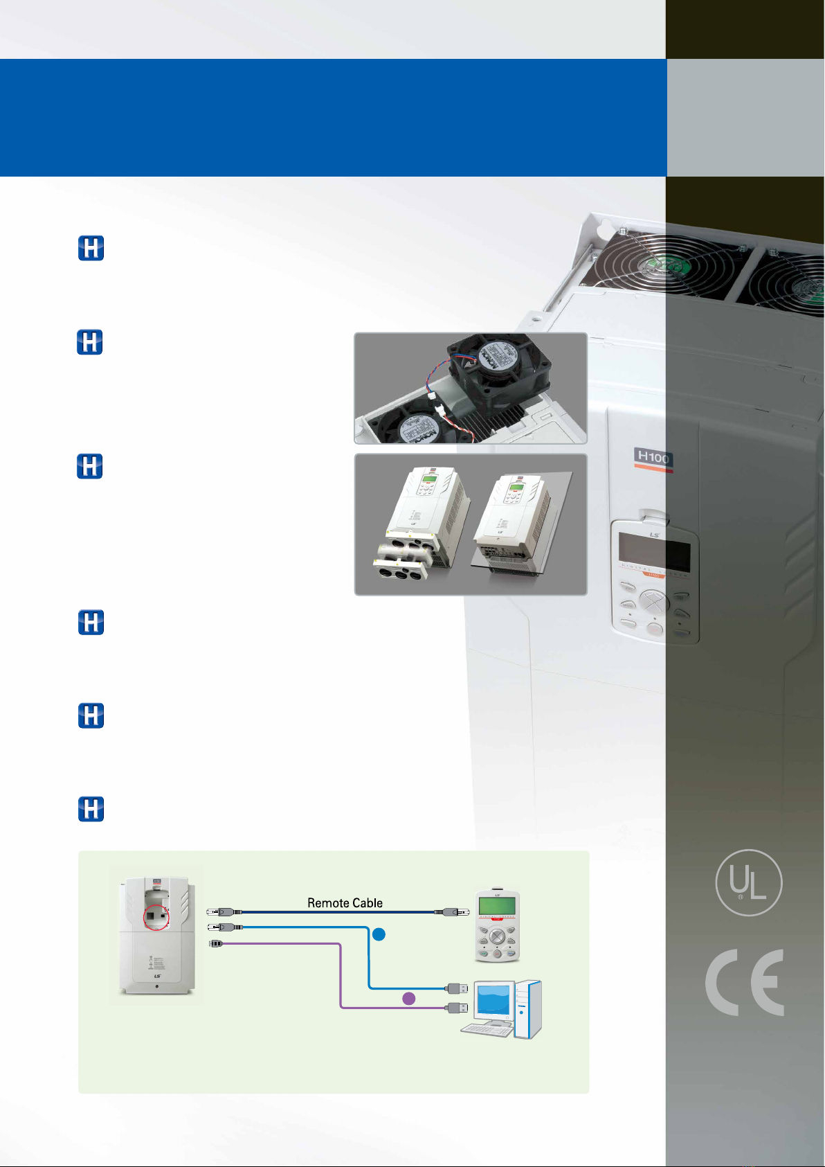
A built-in EMC filter to respond to the specifications for noise reduction
•400V 0.75~30kW, 110~500kW Built-in as default (C3)
•400V 37~55kW Built-in option can be selected (C3)
※ 75~90kW satisfies EMC specifications even without a filter.
Built-in EMC Filter
Energy Saving Drive
UL Plenum Rated
(American standards for conditioner fire safety)
※ Suitable for compartment for air handling/air conditioning
Global Specifications Compliant
04_ LS ELECTRIC
Cancel (ESC) Key
•While in the Edit state, previously saved data are used
•When pressed while switching codes within the group,
it is switched to the very first mode of group.
•When pressed while switching modes, it reverts back to the
monitor mode.
Program (PROG/ENT) Key
•When pressed once, it is changed to Parameter Edit state.
•When pressed after changes, the changed data are saved.
Left/Right Key
•It is used to switch between groups.
(Cursor is used under the Edit state.)
Up/Down Key
•It is used to switch between
codes and edit data values.
Hand (HAND) Key
•It is used to select Keypad
(HAND) operation
•Speed control
(HAND key UP/DOWN)
Auto (OFF) Key
•Off mode or fault reset
Multifunction (MULTI) Key
•It is used to register user codes.
Auto (AUTO) Key
•It is used to select AUTO operation.

Energy Saving Drive
•RS-485 capability is built-in: Modbus-RTU, Metasys N2
•BACnet MS/TP is embedded as standard •LonWorks option can be added
Communication Module
It is easy to change a cooling fan
without opening the cover of a drive.
Easy to Change Cooling Fan
Acquired UL open type & enclosed type 1 certification
•When the conduit option is used, the drive meets UL Enclosed Type 1 specifications
Specification Level Option (Conduit Kit)
If the space is too small, a heat sink can be installed outside the panel.
(110~500kW exposed parts satisfy IP54.)
Flange Type
A built-in DC Reactor effective to improve
power factor and reduce THD is installed.
•DC Reactor built-in as standard for
400V 37~500kW
DC Reactor
DriveView7 can be connected using USB Port or RJ45 terminal.
Software Exclusive for LS Drives
1
2
※
※
Cable 1: Optional; available for separate purchase
Cable 2: Optional; available for separate purchase
(PLC XGT download cable)
H100 _ 05

LSLV-H100 drives improve user convenience
with smart copier.
Maximized User Convenience
Energy Saving Drive
Upload
Parameter 1 Grp.
Parameter 2 Grp.
Parameter 3 Grp.
…………
…………
Smart Copier
Drive
Control
Part
Wire
Parameter
Memory
Read
Parameter
Memory
Download
Smart copier receives from
Drive input/output part
Smart copier
sends to Drive
input/output part
WRITE
READ
Download
Auto-
synchronization
when power on
Drive Input/Output Part
(Flash Memory)
Upload
RJ45(Included if smart copiers are purchased)
Smart copier
06_ LS ELECTRIC
Drive functions under the power-free state.
Power-free Operation
LED is on in case of normal operation;
LED is flickering if errors such as communication occur.
LED Feedback
It is possible to read and write parameters saved in a drive or a smart copier.
Parameters Read/Write
Parameter saved in the smart copier can be downloaded to both the drive I/O
and the control part.
Easy to Install
Upload
Parameter 1 Grp.
Parameter 2 Grp.
Parameter 3 Grp.
…………
…………
Smart Copier
Drive
Control
Part
Wire
Parameter
Memory
Read
Parameter
Memory
Download
Smart copier receives from
Drive input/output part
Smart copier
sends to Drive
input/output part
WRITE
READ
Download
Auto-
synchronization
when power on
Drive Input/Output Part
(Flash Memory)
Upload
Data Flow in Smart Copier

LSLV-H100 drives are miniaturized to reduce the space
for installation, allowing the effective configuration
of environment inside and outside a control panel.
Efficient Use of Space
Energy Saving Drive
H100 _ 07
Main components are optimally deployed through thermal radiation analysis and
3D design to reduce size by 34% compared to iP5A (Volume based).
Reduced Size
50mm
50mm
50mm 50mm
iP5A(650mm) LSLV-H100(584mm)
50mm 50mm2mm 2mm
5.5kW
The size of control board is significantly reduced when multiple drives are installed
by minimizing distance between products installed.
※ Side-by-side installation is unavailable for 37~500kW
Side-by-Side Installation
H
D
W
H
H
D
W
H
Size Reduction
34%

LSVL-H100 drives are intelligent drives equipped with various
protective and operation functions for continuously stable
operation in response to external environmental changes.
Stable System Control
1*%$PNNBOE
1SF1*%4PGU'JMM /PSNBM1*%
1*%3FGFSFODF
4PGU'JMM4FU
4PGU'JMM4FDUJPO
/PSNBM1*%
0QFSBUJPO4FDUJPO
"1'JMM
4UFQ4FU
"14PGU4UFQ5JNF 1*%1*%
'EC7BMVF
U
U
1*%1*%3FG7BMVF
"1
1SF1*%'SFR
'SFRVFODZ
"1
1SF1*%
%FMBZ
Prevents pump damages
caused by dramatic pressure
changes during initial operation
of pumps or inside pumps.
Soft Fill Operation
'SFRVFODZ
'SFR
-JNJU-PX
"5JNFTFUJO"14UBSU3BNQ"DD
#5JNFTFUJO"1&OE3BNQ%FD
"#
5JNF
Prevents pump damage by
changing ramp using
acceleration/deceleration
time setting upon initial pump
operation and stop.
Start Ramp &
End Ramp
Energy Saving Drive
Frequency
Dec Valve Freq
Freq Limit Low
Dec Valve Time
Time
Prevents pump and pipe
damages caused by sudden
pressure changes when pumps
are stopped or a pump valve is
closed, deceleration time can
be set.
Dec Valve Ramp
08_ LS ELECTRIC

Energy Saving Drive
H100 _ 09
1SFTTVSF
3FGFSFODF4FUQPJOU
4FOTPS1PTJUJPO
$PNQFOTBUFE1SFTTVSF3FGFSFODF
1SFTTVSF3FGFSFODFBUˑOP'MPX˒
$PNQFOTBUJPOBNPVOU
1JQF0VUMFU-FOHUI
'MPX
1SFTTVSF
1SFTTVSF-PTT
1SFTTVUF1SFTTVUF
Compensates for hydraulic loss
that occurs when the length of
pipes is long, adding
compensation
rate depending on the inverter
output frequency.
Flow Compensation
MMC is used when a single drive is
used to control multiple motors
in pump systems.
It can control 1 main motor and
5 auxiliary motors
(8 motors if extension I/O installed.)
Multi Motor Control
Aux.
Motor1 Aux.
Motor2 Aux.
Motor3 Aux.
Motor4 Aux.
Motor5 Main
Motor
00:00 Pre-Heat
Fx
Speed-L
Speed-H
02:00
04:00
06:00
08:00
10:00
12:00
14:00
18:00
16:00
20:00
22:00
24:00
00:00 Pre-Heat
Fx
Speed-L
Speed-H
02:00
04:00
06:00
08:00
10:00
12:00
14:00
18:00
16:00
20:00
22:00
24:00
SunThuWedTueMon SatFri
ۑЃրটڝࢼŝ
00:00
Pre-Heat
Fx
Speed-L
Speed-H
02:00
04:00
06:00
08:00
10:00
12:00
14:00
18:00
16:00
20:00
22:00
24:00
00:00 Pre-Heat
Fx
Speed-L
Speed-H
02:00
04:00
06:00
08:00
10:00
12:00
14:00
18:00
16:00
20:00
22:00
24:00
SunThuWedTueMon SatFri
ۑЃրটڝࢼŝ
RTC (Real Time Clock) is used so
that selected functions are operable
during the set time.
(Possible to set different functions
including Fx, Rx, multiple
acceleration/deceleration time,
multiple frequency, PID related
functions and pre-heat.)
Scheduling (Time Event: Real Time Clock)

Energy Saving Drive
With reinforced system-based functions and performance,
LSVL-H100 drives not only provide optimum solution to
applications for cooling/heating and water treatment,
but also ensure energy saving and pleasant environment.
Stable System Control
10_ LS ELECTRIC
Upon pump operation, the efficiency of pumps may decline when foreign substances
are stuck in an impeller. Pump Clean removes the foreign substances to extend the
pump life and reduce any loss.
Pump Clean
Pipe flow increases and conduit pressure decreases as the number of auxiliary motors
increases.
To compensate this‘, Aux Motor PID Compensation’is used to compensate pressure loss
suitable for the given motor when operating auxiliary motors.
Aux Motor PID Compensation
When an emergency such as fire occurs at suction/exhaust fans, but hardware did not fail nor
had a critical defect, the drive is continuously operated to protect other systems under the set
frequency and direction.
Fire Mode
Commercial energy consumption is compared to the amount of energy used by the drive to
calculate the amount of energy saved.
Energy-saving Display (Payback Counter)
When the drive restarts after it was stopped due to power interruption upon communication
control‘, Power-on Resume’is used to follow the previous control command.
Power-on Resume
It is used to put the drive on standby and restarts it using PID in order to reduce motor loss
as much as possible.
Sleep, Sleep Boost, Wake-up
Establishes load (current & power) curves based on drive frequency so as to make load
characteristics curve required for ‘Under Load’ and ‘Pump Clean.’
Load Tuning

Energy Saving Drive
H100 _ 11
The drive outputs voltage for the drive by controlling the level of boost
to fit the load by itself.
Auto Torque Boost
When a control command is made in the Flow/Oiling Systems,
lubrication signals are output for a certain period before the motors are started.
Drive control is immediately started from the signal output point until the
signals are turned off after the set time.
Lubrication Control
When a Damper exists in the system configuration, the drive will command the Damper to
open/close or receive feedback signals for protection.
Damper Control
When the drive is operated under frequency that is beyond the set frequency and source
(voltage, current, and etc.) values to be detected are above or below the user set values,
it generates a trip or activates a relay for protective operation.
Level Detection
Upon PID operation, pipe damages or leakage is detected to display a warning or a trip.
Detection of Pipe Broken
When running pumps including No Flow and Dry Pumps under the set frequency, the drive
issues warning functions; and when trip is generated, Free-Run, stop after deceleration
can be selected via parameters.
Under Load Protection
Pre-heats motors by outputting direct current when the motors are at fixed time state in
order to prevent condensation of the motors.
Pre-Heat
Upon loss or momentary interruption of input power, if KEB is set, the drive maintains DC
Link Voltage using regeneration energy of the motor is used during the interruption period.
KEB, Kinetic Energy Buffering
If a particular application is selected, frequently used parameters and set values are
changed and registered in a macro group.
Macro Setting

12_ LS ELECTRIC
Fan and Pump
H100
Model & Type
※75~90kW satisfies EMC class 3
Motor Rating 3-Phase 200V 3-Phase 400V
LSLV0008H100-2CONN
LSLV0015H100-2CONN
LSLV0022H100-2CONN
LSLV0037H100-2CONN
LSLV0055H100-2CONN
LSLV0075H100-2CONN
LSLV0110H100-2CONN
LSLV0150H100-2CONN
LSLV0185H100-2CONN
LSLV0370H100-4COND
LSLV0450H100-4COND
LSLV0550H100-4COND
LSLV0370H100-4COFD
LSLV0450H100-4COFD
LSLV0550H100-4COFD
0.75 kW
1.5 kW
2.2 kW
3.7 kW
5.5 kW
7.5 kW
11 kW
15 kW
18.5 kW
22 kW
30 kW
37 kW
45 kW
55 kW
75 kW
90 kW
110 kW
132 kW
160 kW
185 kW
220 kW
250 kW
315 kW
355 kW
400 kW
500 kW
LSLV0008H100-4COFN
LSLV0015H100-4COFN
LSLV0022H100-4COFN
LSLV0037H100-4COFN
LSLV0055H100-4COFN
LSLV0075H100-4COFN
LSLV0110H100-4COFN
LSLV0150H100-4COFN
LSLV0185H100-4COFN
LSLV0220H100-4COFN
LSLV0300H100-4COFN
LSLV0750H100-4COFD
LSLV0900H100-4COFD
LSLV1100H100-4COFD
LSLV1320H100-4COFD
LSLV1600H100-4COFD
LSLV1850H100-4COFD
LSLV2200H100-4COFD
LSLV2500H100-4COFD
LSLV3150H100-4COFD
LSLV3550H100-4COFD
LSLV4000H100-4COFD
LSLV5000H100-4COFD
LSLV 0055 H100 4 C O FN
Motor Capacity
0008-0.75kW 0150-15kW 0750-75kW 2500-250kW
0015-1.5kW 0185-18.5kW 0900-90kW 3150-315kW
0022-2.2kW 0220-22kW 1100-110kW 3550-355kW
0037-3.7kW 0300-30kW 1320-132kW 4000-400kW
0055-5.5kW 0370-37kW 1600-160kW 5000-500kW
0075-7.5kW 0450-45kW 1850-185kW
0110-11kW 0550-55kW 2200-220kW
Keypad Type
C: LCD Keypad
Reactor
D: Built in DC Reactor
N: Non DC Reactor
EMC Filter
F: Built-in EMC
N: Non EMC
Input Voltage
2 : 3-phase 200~240V
4 : 3-phase 380~480V
UL Type
O: UL Open
E : UL Type1
Series Name

H100 _ 13
Energy Saving Drive
Input & Output Specification Energy Saving
3-Phase 200V (0.75~18.5kW)
Model Name LSLV□□□□H100-2□□□□ 0008 0015 0022 0037 0055 0075 0110 0150 0185
Applied Motor HP
1.0 2.0 3.0 5.0 7.5 10 15 20 25
kW
0.75 1.5 2.2 3.7 5.5 7.5 11 15 18.5
Output Rating
Rated Capacity (kVA)
1.9 3.0 4.5 6.1 8.4 11.4 16.0 21.3 26.3
Rated Current
5 8 12 16 22 30 42 56 69
Output Frequency
0~400Hz
Output Voltage (V)
3-Phase 200~240V
Input Rating
Service Voltage (V)
3-Phase 200~240VAC (-15%~+10%)
Input Frequency
50~60Hz( 5%)
Rated Current (A)
4.9 8.4 12.9 17.5 23.7 32.7 46.4 62.3 77.2
Weight (kg)
3.3 3.3 3.3 3.3 3.3 3.3 3.3 4.6 7.1
3-Phase 400V (0.75~22kW)
Model Name LSLV□□□□H100-4□□□□ 0008 0015 0022 0037 0055 0075 0110 0150 0185 0220
Applied Motor HP
1.0 2.0 3.0 5.0 7.5 10 15 20 25 30
kW
0.75 1.5 2.2 3.7 5.5 7.5 11 15 18.5 22
Output Rating
Rated Capacity (kVA)
1.9 3.0 4.5 6.1 9.1 12.2 18.3 23.0 29.0 34.3
Rated Current
2.5 4 6 8 12 16 24 30 38 45
Output Frequency
0~400Hz
Output Voltage (V)
3-Phase 380~480V
Input Rating
Service Voltage (V)
3-Phase 380~480VAC (-15%~+10%)
Input Frequency
50~60Hz( 5%)
Rated Current (A)
2.4 4.2 6.5 8.7 12.2 17.5 26.5 33.4 42.5 50.7
Weight (kg)
3.3 3.3 3.3 3.3 3.3 3.3 3.4 4.6 4.8 7.5
3-Phase 400V (30~90kW)
Model Name LSLV□□□□H100-4□□□□ 0300 0370 0450 0550 0750 0900
Applied Motor HP
40 50 60 75 100 125
kW
30 37 45 55 75 90
Output Rating
Rated Capacity (kVA)
46.5 57.1 69.4 82.0 108.2 128.8
Rated Current
61 75 91 107 142 169
Output Frequency
0~400Hz
Output Voltage (V)
3-Phase 380~480V
Input Rating
Service Voltage (V)
3-Phase 380~480VAC(-15%~+10%)
Input Frequency
50~60Hz(±5%)
Rated Current (A)
69.1 69.3 84.6 100.1 133.6 160.0
Weight (kg) / EMC Built-in
7.5 26 35 35 43
Weight (kg) / Non EMC
- 25 34 34
3-Phase 400V (110~500kW)
Model Name LSLV□□□□H100-4□□□□ 1100 1320 1600 1850 2200 2500 3150 3550 4000 5000
Applied Motor HP
150 200 250 300 350 400 500 550 650 800
kW
110 132 160 185 220 250 315 355 400 500
Output Rating
Rated Capacity (kVA)
170 201 248 282 329 367 467 520 587 733
Rated Current
223 264 325 370 432 481 613 683 770 962
Output Frequency
0~400Hz
Output Voltage (V)
3-Phase 380~500V
Input Rating
Service Voltage (V)
3-Phase 380~500VAC(-15%~+10%)
Input Frequency
50~60Hz(±5%)
Rated Current (A)
215.1 254.6 315.3 358.9 419.1 469.3 598.1 666.4 751.3 938.6
Weight (kg)
55.8 55.8 74.7 74.7 120.0 120.0 185.5 185.5 185.5 265
•Motor capacity is based on use of 4-pole standard motors.
•200V Class is for 220V and 400V Class is for 440V.
•Rated output current is limited depending on the carrier frequency (CON-04) setting.
•400V 0.75~30kW, 110~500kW, EMC filter is built-in as default. (C3)
•400V 37~55kW, EMC filter is provided as built-in product option. (C3)
•400V 75~90kW, products satisfy EMC specifications even without a filter.

14_ LS ELECTRIC
Fan and Pump
H100
Product Details
Item Description
Control
Control Mode
V/F control, slip compensation
Frequency Set Resolution
Digital command: 0.01Hz
Analog command: 0.06Hz (based on 60Hz)
Control Degree of Frequency
1% of the maximum output frequency
V/F Pattern
Liner, squared overload reduction and user V/F
Overload Capacity
0.75~90kW Rated Current: 120% 1 minute
110~500kW Rated Current: 110% 1 minute
Torque Boost
Manual torque boost, Automatic torque boost
Control
(Operation)
Drive Mode
Optional: Keypad, terminal board or communication control
Frequency Setting
Analog mode: -10~10V, 0~10V, 0~20mA
Digital mode: Keypad and pulse train input
Control Functions
PID control, 3-Wire control, Frequency limitation, Secondary Functions, Forward/
Reverse rotation prohibited, DC braking, Commercial power switching, Speed search,
Power braking, Reduction of leakage, Up-Down control, DC braking Flux braking, Frequency pump,
Slip compensation, Automatic restart, Automatic tuning, Energy buffering control, Energy-saving control
Input
Multifunctional
Terminal (7 points)
The following functions can be set using IN-65~71 code parameters between PNP(Source) and NPN(Sink).
Forward Operation, Reset, Emergency stop, Multi-step frequency – High/Mid/Low, DC braking during stop,
Pre-Heat, Frequency increase, 3-Wire, Optional: Acceleration, deceleration or stop, MMC interlock,
Reverse Operation, Pump cleaning, External trip, Jog control, Multi-step acceleration/deceleration-High/
Mid/Low, Secondary motor selection, RTC(Time event function), Frequency decrease, Analog command
frequency fixation, Switching to normal operation during PID operation,
Pulse Train
0~32kHz, Low Level: 0~0.8V, High Level: 3.5~12V
Output
Multifunctional Open
Collector Terminal
Failure output & drive control status output:
DC 26V, 50mA or below
Failure (Fault) Relay
Terminal
N.O. : AC 250V, 2A or below, DC30V, 3A or below
N.C. : AC 250V, 1A or below, DC30V, 1A or below
Multifunctional Relay
Terminal
AC250V, 5A or below, DC30V, 5A or below
Analog Output
0~12Vdc(0~20mA): Optional among frequency, output current, output voltage and DC voltage.
Pulse Train
Maximum 32kHz, 0~12V
Protective
Functions
Trip
Over-current trip, Trip caused by external signals, ARM short-circuit current trip, Overheat trip, Pipe broken trip,
Input open-phase trip Ground trip, Motor overheat trip, IO board connection trip, No Motor trip, Parameter Write trip,
Emergency stop trip, Command loss trip, External memory error, CPU watchdog trip, Motor under-load trip,
Overvoltage trip, Temperature sensor trip, Drive overheat, Option trip, Output open-phase trip, Drive overload trip,
Fan trip, Low voltage trip during operation, Low voltage trip, Analog input error, Motor overload trip,
Keypad command loss trip, Damper trip, Level Detect trip, All auxiliary motor failure trip, Pump clean failure (fault)
Warning
Command loss trip warning, overload warning, under-load warning, drive overload warning, fan operation
warning, damping resistance brake percentage warning, capacitor life warning, pump clean warning,
Fire Mode warning and LDT warning
Instant Power Interruption
Below 8 ms: Continuous operation (within the rated input voltage and rated output)
8 ms or above: Automatic restart operation
Structure/
Operational
Environment
Cooling mode
Forced air-cooling
Protective structure
IP20/UL Open(default), UL Enclosed Type 1(option)
Ambient temperature
With no ice or frost at -10~50°C(14~122°F)
(At 40°C or above, derating of 2.5%/1°C current. At 50°C, 75% of the rated current is operable).
Ambient humidity
Relative humidity of 95% RH or below (without dew formation)
Storage temperature
-20 ~ 65 ºC (-4~149°F)
Ambient environment
Without corrosive gas, combustible gas, sludge and dust (Pollution Degree 3 Environment)
Altitude
Maximum 1000m above sea level for standard operation.
From 1000 to 4000m, the rated input voltage and rated output current of the drive must be derated by
1% for every 100m.
Vibration
9.8m/sec2(1.0G) or below
Ambient atmospheric pressure
70~106kPa

H100 _ 15
Energy Saving Drive
Wiring
※The default value is displayed in blue color
1
1
1
1
1/1
* 7
/1/
0/
7 5
0''
1
4
4
4(
"0
"0
&(
"
#
"
$
"
$
"
$
"
$
1
1
$.
73
7
$.
*
"0
5TFOTPS
*5FSNJOBM7 $.
5*
.VMUJGVODUJPO*OQVU 344JHOBM*OQVU
&YUFSOBM71PXFS
'BVMU4JHOBM0VUQVU
3FMBZ0VUQVU
3FMBZ0VUQVU
3FMBZ0VUQVU
3FMBZ0VUQVU
"OBMPH7PMUBHF
$VSSFOU0VUQVU
"OBMPH7PMUBHF
0VUQVU
5FSNJOBUJOH
3FTJTUBODF
70 *0
"OBMPH4FUUJOH
'SFRVFODZ4FUUJOH
1VMTF5SBJO
$
.VMUJGVODUJPO$PNNPO

16_ LS ELECTRIC
Fan and Pump
H100
Power Terminal
Power Terminal Marks & Details
0.75~30kW(3-Phase)
DC Reactor
Short Bar
[Note1]
Terminal Mark Name Description
R(L1) / S(L2) / T(L3)
AC power input terminal Mains supply AC power connections.
P1(+) / P2(+)
DC reactor terminal DC Reactor wiring connection.
(When you use the DC Reactor, must remove shortbar.)
P2(+) / N(-)
DC link terminal DC voltage terminals.
P2(+) / B
Braking resistor terminal Braking resistor wiring connection.
U / V / W
Motor output terminal 3-phase induction motor wiring connections.
Note 1) Short Bar should be removed when wiring DC Reactor.
37~90kW(3-Phase)
DC Reactor
Short Bar
Terminal Mark Name Description
R(L1) / S(L2) / T(L3)
AC power input terminal Mains supply AC power connections.
P2(+) / N(-)
DC link terminal DC voltage terminals.
P3(+) / N(-)
Brake unit terminal Brake unit wiring connection.
U / V / W
Motor output terminal 3-phase induction motor wiring connections.

H100 _ 17
Energy Saving Drive
Power Terminal Marks & Details
110~250kW (3-Phase)
DC Reactor
Short Bar
Terminal Mark Name Description
R(L1) / S(L2) / T(L3)
AC power input terminal Mains supply AC power connections.
B
-It can not be used.
P(+) / N(-)
DC link terminal
(or Brake unit terminal)
Connect to DC voltage terminal.
(or Brake unit wiring connection)
U / V / W
Motor output terminal 3-phase induction motor wiring connections.
315~500kW (3-Phase)
DC Reactor
Short Bar
Terminal Mark Name Description
R(L1) / S(L2) / T(L3)
AC power input terminal Mains supply AC power connections.
P(+) / N(-)
DC link terminal
(or Brake unit terminal)
Connect to DC voltage terminal
(or Brake unit wiring connection)
U / V / W
Motor output terminal 3-phase induction motor wiring connections.

18_ LS ELECTRIC
Fan and Pump
H100
Control Circuit Terminal
Input Terminal Marks & Details
Classification Terminal Mark Name Description
Selection of
Contact Points
P1-P7 Multifunctional Input
1~7 Terminal
It can be used by setting multifunctional input.
Default values from the factory are as follows:
•
P1: Fx
•
P2: Rx
•
P3: BX
•
P4: RST
•
P5: Speed-L
•
P6: Speed-M
•
P7: Speed-H
CM Sequence Common Terminal BCommon terminal of contact point input and analog I/O terminal
Analog Input
VR Power Terminal
for Frequency Setting
Power for analog frequency setting:
•
Max. output voltage: 12V
•
Max. output current: 12mA
•
Volume resistivity: 1~10kΩ
V1 Frequency Setting(Voltage)
Terminal
Frequency is set depending on the voltage supplied to V1 terminal.
•
Unipolar: 0~10V(Max. 12V)
•
Bipolar: -10~10V(Max. ±12V)
I2 Frequency Setting
(Current/Voltage) Terminal
Frequency is set depending on the current capacity supplied to I2
terminal. V2 can be used by selecting analog voltage/current input
terminal setting switch (SW4).
•
nput current: 0~20mA
•
Max. input current: 24mA
•I
nput resistance 249Ω
TI Frequency Setting (Pulse Train)
Terminal
Frequency is set as 0~32kHz.
Low Level : 0~0.8V, High Level : 3.5~12V
5.5~90kW
110~500kW
A2 C2 A4 C4 Q1 EG P5 P6 P7 CM VR V1 I2 CM S+ S- SG
A1 B1 C1 A3 C3 A5 C5
24V
P1 P2 P3 P4 CM TI
AO1 AO2 CM
A2 C2 A4 C4 A5 C5 P5 P6 V1 I2 CM S+ S- SGP7 CM VR
A1 B1 C1 A3 C3 NC Q1 EG P3 P4 TI
AO1 AO2 CM24V
P1 P2
A2 C2 A4 C4 Q1 EG P5 P6 P7 CM VR V1 I2 CM S+ S- SG
A1 B1 C1 A3 C3 A5 C5
24V
P1 P2 P3 P4 CM TI
AO1 AO2 CM
A2 C2 A4 C4 A5 C5 P5 P6 V1 I2 CM S+ S- SGP7 CM VR
A1 B1 C1 A3 C3 NC Q1 EG P3 P4 TI
AO1 AO2 CM24V
P1 P2

H100 _ 19
Energy Saving Drive
Output/Communication Terminal Marks & Details
Classification Terminal Mark Name Description
Analog Output
AO Voltage/Current Output Terminal
One of the following is chosen and output: Output frequency, output
current, output voltage and DC voltage. The following voltage/current
output can be chosen by selecting analog voltage/current
output terminal setting switch (SW5).
•
Output voltage: 0~10V
•
Max. output voltage/current: 12V, 10mA
•
Output current: 0~20mA
•
Max. output current: 20mA
•
Factory default value: Frequency
Contact Point
Q1
Multifunctional
(Open Collector) Output/
Pulse Output Terminal
As a multifunctional output signal or pulse output, one of the following is chosen: Output
frequency, output current, output voltage and DC voltage. DC 26V, 50mA or below
Pulse output terminal
•
Output frequency: 0~32kHz
•
Output voltage: 0~12V
EG Common Terminal Common ground terminal for external power of open collector
24 24V Power Terminal (Note)
•
Max. output current: 100mA
•
Do not use external 24V except for PNP-mode terminal block
A1/C1/B1
Abnormal Signal
Output/Multifunctional
Output Terminal
When power is cut-off to protect the product, signals or multifunctional signals are output.
(N.O. : AC250V 2A or below, DC 30V 3A or below
N.C. : AC250V 1A or below and DC 30V 1A or below)
•
At abnormal state: A1-C1 connected (B1-C1 disconnected)
•
At normal state: B1-C1 connected (A1-C1 disconnected)
•
Factory default value: Frequency
A2/C2 – A5/C5 Multifunctional Relay Output A
Contact Point
Multifunctional output terminal such as signals at operation is defined and used.
(AC 250V 5A or below and DC 30V 5A or below)
S+/S-/SG RS-485 Signal Input Terminal RS-485 signal line
Note)
Available only when used in PNP mode.

20_ LS ELECTRIC
Fan and Pump
H100
Wires and Screw Specifications
Earth Wire & I/O Wiring Specifications
Product (kW)
Ground Wire I/O Wiring
mm2AWG mm2AWG
R/S/T U/V/W R/S/T U/V/W
3-Phase
200V Class
0.75
3.5
12 1.5 1.5 16 161.5
2.2
3.7 2.5 2.5 14 14
5.5
10
10
4 4 12 12
7.5 6 6 10 10
11 10 10 8 8
15
14
616 16 6 6
18.5 25 22 4 4
3-Phase
400V Class
0.75
3.5
12 1.5 1.5 16 161.5
2.2
3.7 2.5 2.5 14 14
5.5
4
12
2.5 2.5 14 14
7.5 4 2.5 12 14
11 4 4 12 12
15 16 9 6 6 10 10
18.5 16 10 6 8
22 14616 10 6 8
30 25 16 4 6
37
25 4
25 25 4 4
45 25 25 4 4
55 50 50 1/0 1/0
75 38270 70 1/0 1/0
90 70 70 1/0 1/0
110 50×2 1×2 70×2 70×2 2/0×2 2/0×2
132 95×2 95×2 3/0×2 3/0×2
160 50×2, 70×2 1/0×2 95×2 95×2 3/0×2 3/0×2
185 70×2, 95×2 3/0×2 120×2 120×2 4/0×2 4/0×2
220 95×2 250×2 185×2 185×2 350×2 350×2
250 300×2 185×2 185×2 350×2 350×2
315 60×4, 150×2 2/0×4 95×4, 300×2 95×4, 300×2 3/0×4, 600×2 3/0×4, 600×2
355 70×4, 150×2 3/0×4 120×4, 300×2 120×4, 300×2 4/0×4, 600×2 4/0×4, 600×2
400 95×4, 200×2 4/0×4 120×4, 400×2 120×4, 400×2 4/0×4, 700×2 4/0×4, 700×2
500 120×4, 250×2 4/0×4, 750×2 185×4, 630×2 185×4, 630×2 350×4, 1500×2 350×4, 1500×2
This manual suits for next models
38
Table of contents
Other LS ELECTRIC DC Drive manuals
Popular DC Drive manuals by other brands

Emerson
Emerson Dixell XEV23D Installing and operating instructions

Bosch
Bosch Classic+ Line 0 275 007 003 Original instructions

SOMFY
SOMFY Sunea 40 Solar io instructions

Minarik
Minarik HTL05-D-4Q quick start guide

Lenze
Lenze SMD Series reference guide

Power Electronics
Power Electronics SD700 Series Applications manual