Guida per la configurazione del sensore DQL011.1 SOMMER USH-9
Introduzione
Il sensore di livello DQL011.1 è già configurato per l’uso con i data
logger LSI Lastem. Tuttavia, dopo la fase di installazione, è richie-
sto l’intervento dell’installatore per l’aggiustamento di alcuni pa-
rametri legati alla posizione del sensore. Per l’operazione è neces-
sario disporre di un PC munito di porta USB sul quale è installato
un programma di emulazione terminale (es. Hyper Terminal di
Windows).
Configurazione sensore
Per la configurazione del sensore, procedere come segue:
1. Collegare al PC il dispositivo
USB-RS485 fornito a corredo. Il
Sistema Operativo dovrebbe
installare il driver in modo au-
tomatico. Se così non fosse,
procedere all’installazione del
driver in modo manuale, ricer-
candolo nella chiavetta USB
SOMMER fornita a corredo.
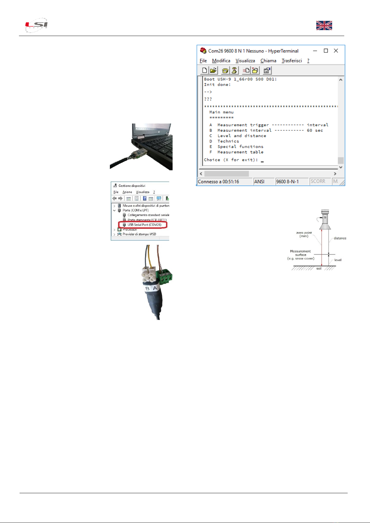
2. Identificare la porta seriale as-
sociata al dispositivo.
3. Collegare i fili del sensore al convertitore
USB-RS485:
➢giallo: morsetto A
➢grigio: morsetto B
4. Collegare i fili del sensore
all’alimentazione*:
➢marrone: + 9÷27 Vcc
➢bianco: 0 Vcc
*E-Log fornisce 12Vcc sui morsetti 31+, 32-,
mentre M-Log ed R-Log sui morsetti 28-, 30+.
5. Avviare sul PC un programma di emulazione terminale (ad es.
Hyper Terminal di Windows) impostando i parametri di co-
municazione come segue:
➢Porta seriale: <la porta seriale associata al dispositivo
identificata al punto 2>
➢Bit per secondo: 9600
➢Bit di dati: 8
➢Parità: Nessuno
➢Bit di stop: 1
➢Controllo di flusso: Nessuno
6. Accendere il sensore. All’accensione si presenta la scritta
Boot USH-9 1_66r00 S00 D01!
Init done!
7. Digitare 3 volte il tasto ‘ ? ’ per accedere al menu di configura-
zione.
8. Premere C per accedere al menu Level and distance e succes-
sivamente B Level/distance test… per eseguire una lettura di
test.
9. Modificare i parametri
➢D Distance, zero level
➢E Distance, far limit
in base al tipo di misura che si
desidera avere dal sensore (di-
stanza o livello) ed ai valori letti
nel test al punto precedente.
10. Premere Xper tornare al menu principale, quindi premere D
per accedere al menu Technics per impostare le uscite analo-
giche.
11. Impostare i parametri
➢F IOUT1 settings
➢IOUT1, 4-20 mA span
in base al tipo di misura scelto ed ai valori impostati al punto
9.
Configurazione data logger E/R/M-Log
Tramite il programma 3DOM modificare la configurazione del data
logger come segue:
➢Aggiungere il sensore DQL011.1 dalla libreria dei sensori.
➢Nella scheda Generale adeguare il nome al tipo di misura
scelta (distanza o livello). Se si utilizzano più sensori dello
stesso tipo, personalizzare il nome delle misure per distin-
guerle le une dalle altre.
➢Nella scheda Parametri modificare i parametri della Scala
utente in base ai valori impostati nell’uscita IOUT1 del sen-
sore.
➢Nella scheda Elaborazioni scegliere le elaborazioni desidera-
te.
Per maggiori informazioni sulla modifica della configurazione, fare
riferimento ai manuali del data logger e di 3DOM.