LSL Products TOAD-CHARGE User manual

1
2
4
Towed Vehicle
Battery Charger
STEP ONE: For safety's sake, disable your house battery charger and solar panels before disconnecting the battery cable from the Negative
post on the motorhome starting and house batteries. Next, identify a suitable point for connecting the kit's wire harness to the Positive and
Negative/Chassis Ground sides of your motorhome's starting or house batteries (either at your motorhome's battery isolator or directly to the
battery posts), but don't connect the wires yet. (NOTE: Connecting the harness to the motorhome's HOUSE batteries has the advantage of
allowing the towed vehicle to be recharged overnight when parked with AC hookups.) Route the harness rearward to your motorhome's
receiver hitch, using the Nylon Wire Ties (included in the kit) as the means of attachment every few feet or so. Take care to keep the harness
from touching hot exhaust parts, sharp edges or moving parts of the motorhome drivetrain. After you reach the hitch at the back of the motor
home, cut off any surplus wire, leaving about a foot of harness dangling beyond the hitch. Save the surplus wire for use in STEP TWO below.
GENERAL INFORMATION — TOAD-CHARGE™ keeps the battery in your towed vehicle (or "Toad") charged while it is being towed behind your motorhome, thereby
solving the battery discharge problems often caused by auxiliary braking systems or leaving the steering wheel unlocked while towing. The kit connects between your
motorhome's starting or house batteries and the towed vehicle's battery, using the motorhome's engine to supply up to 10 amps of current to the towed vehicle's battery.
The kit consists of several components: A Charge Controller installed in the towed (or "Dinghy") vehicle's engine compartment monitors the charging current, and
prevents reverse current flow when the motorhome engine is started. A 15 Amp Circuit Breaker installed near the motorhome starting battery protects against excessive
current flow due to wiring faults or a dead battery. The Charge Controller and Circuit Breaker are connected together by wire harnesses which are cut to desired lengths
from 40 or 60 feet of 12 gauge dual-conductor wire. Detachable connectors on the tow bar harness allow it to be stowed along with the tow bar when not needed. The
harnesses include a dedicated ground wire, thereby minimizing the voltage drop that might otherwise be present when relying on the motorhome's trailer hitch wiring.
Step-By-Step Installation Instructions
CAUTION!
USE CARE AROUND BATTERIES —
SPARKS CAN IGNITE HYDROGEN GAS.
SHORT CIRCUITS CAN CAUSE BURNS
OR FIRE. CORROSIVE ACID CAN CAUSE
SKIN BURNS OR BLINDNESS.
USE CARE IN DRILLING HOLES NOT TO
CONTACT ANY ELECTRICAL WIRING —
HAZARD OF SHOCK, FIRE, BURNS.
!
STEP TWO: Mount the 15 Amp Circuit Breaker next to your chosen
motorhome battery connection point, using 2 sheet metal screws (included)
in 1/8" drilled holes (as shown below). WARNING: DO NOT OMIT THE
CIRCUIT BREAKER, OR A FIRE HAZARD WILL RESULT! On the end of
the harness, remove several feet of white plastic covering to expose the Red
and Black wires. Cut these wires just long enough to reach the Circuit
Breaker (for the Red wire) and Negative/Chassis Ground (for the Black wire).
!
Wire
Ring Terminal
(side view)
Crimp Here After
Inserting Wire
1/4"
Next, take the surplus cable left over from STEP ONE, split
the white plastic covering off it to expose the Red wire inside,
and cut this wire so that it is long enough to connect between
the 15 Amp Circuit Breaker and your previously-chosen
Positive connection point. Strip both ends of this wire,
crimping a small yellow ring terminal to one end before
attaching it to the BATTERY terminal on the Circuit Breaker.
Crimp either a small, medium or large yellow ring terminal to
the other wire end before attaching it to your chosen Positive
connection point.
TOP VIEW
SIDE VIEW
(mark to drill holes here)
Mounting Surface
1/8" Hole
Mounting
Screw
TOAD-CHARGE™15 AMP
CIRCUIT BREAKER
LSL Products • 5807 Babcock Rd. #108
San Antonio, TX 78240 • 877-257-4655
www.LSLProducts.com
Next, strip approx. 1/2" of insulation off this Red wire, and crimp a small yellow ring terminal to
it before connecting it to the HARNESS terminal on the circuit breaker. In a similar manner,
crimp a ring terminal (small, medium or large size) to the cable's Black wire before connecting it
to the Negative/Chassis Ground connection point you previously chose in STEP ONE above.
STEP FOUR: Inside your towed vehicle's engine compartment, identify points for connecting the Charge Controller to the vehicle's battery
terminal bolts, using a pair of small, medium or large-diameter yellow ring terminals. Use 2 sheet metal screws or Nylon Wire Ties to mount the
Charge Controller near your battery connection points (similar to circuit breaker mounting in STEP 2 above). For safety's sake, disconnect the
vehicle's battery cable from the Negative post on the battery before proceeding.
Next, take one end the surplus harness wire left over from STEP 2 above, strip 1/4" off its red and black wires before connecting them to the
House or
Starting
Battery(s)
RED
Hitch
TOAD-CHARGE™15 AMP
CIRCUIT BREAKER
BLACK
Dinghy
Vehicle
Battery
Tow Bar Harness
Motor Home Harness
Dinghy Vehicle Harness
15 Amp Circuit Breaker
Charge Controller
MOTOR
HOME
TOW
BAR
DINGHY
VEHICLE
RED
BLACK
Wire Strip Gauge
1/2"
3/4"
(19 MM)
(13 MM)
1/4"
(6.5 MM)
Female
Connector
Female
Connector
Male
Connector
Male
Connector
(See steps 1-3 below)
(See step 6 below)
(See steps 4-5 below)
MH terminals on the Charge Controller (Red wire to MH+ terminal, Black wire to MH– terminal). Secure the wires near the connector with another Nylon Wire Tie
(as in STEP 3 above). Route the other end of this harness from the charge Controller to the dinghy vehicle's front grille, using Nylon Wire Ties to secure it along
the way. After routing it to exit through the grille near a tow bar attachment point, cut off any surplus length, leaving about a foot of harness dangling next to the
tow bar. Finally, repeat the process described above in STEP 3 to attach a FEMALE (smaller) plug-in connector and MALE "dust cap" to it.
3
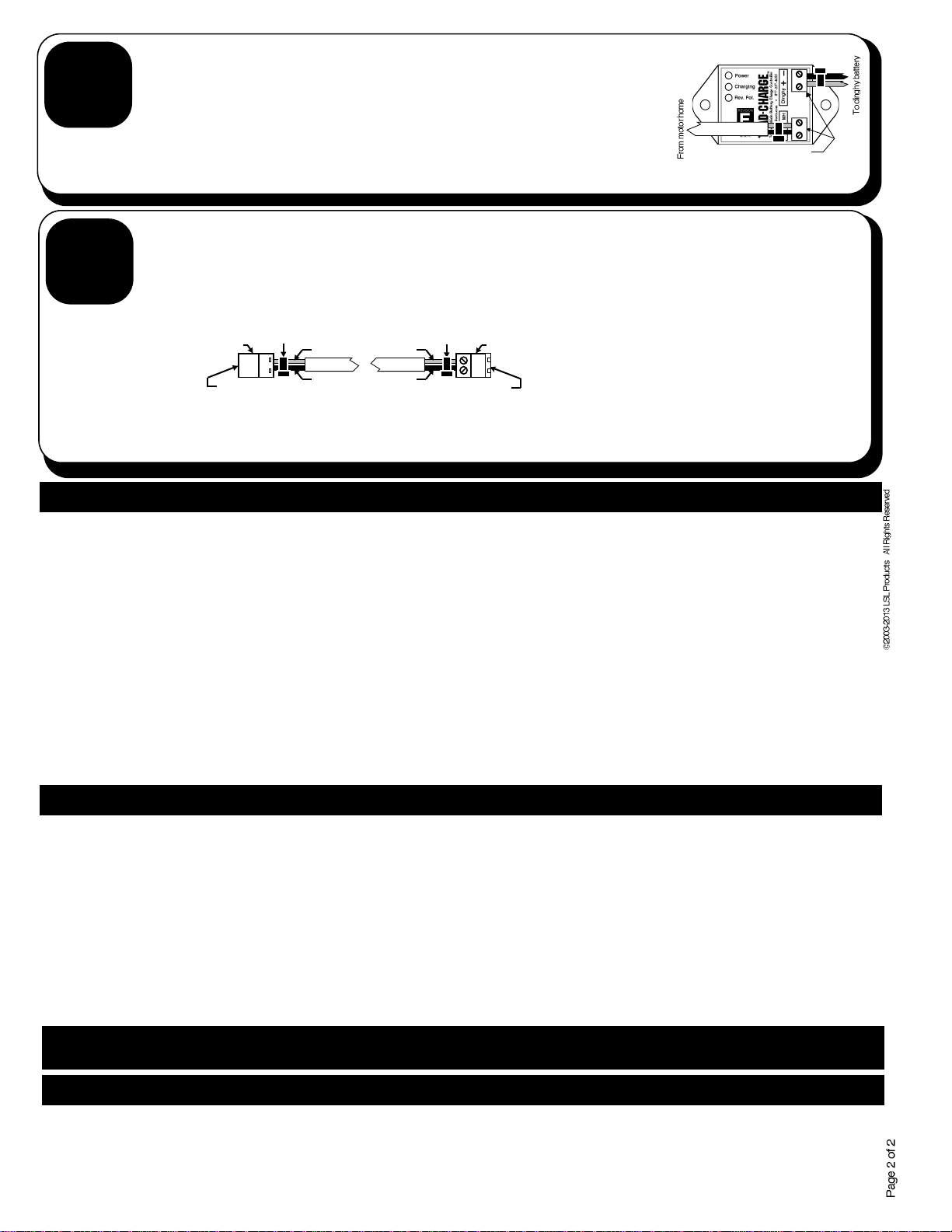
STEP THREE: On the motorhome hitch end of the harness, remove approx. 1" of the white plastic outer covering. Strip approx. 1/4" of
insulation off the exposed red and black wires, twisting any frayed small copper wires back together. Next, fully insert these bare wires into
one of the green FEMALE (smaller) connectors included in the kit before tightening the connector screws to captivate the wires. The Red wire
goes to the connector pin marked with a red stripe; the Black wire goes to the other, unmarked pin. Do not overtighten the connector
screws. Slip a black Nylon Wire Tie around the red and black wires next to the connector, tighten it snugly, and then snip off its excess end.
Finally, loop a piece of green plastic keeper cord through the black wire behind the connector, through a black plastic bead, and then connect
both ends of the cord to a MALE (larger) connector. This connector serves as a "dust cap" whenever the cable is not in use.
Male (larger) Connector
Green Plastic
Keeper Cord
Tighten Screws
After Inserting Both
Ends of Cord
Black Bead
Nylon Wire Tie
Strip 1"
Strip 1/4"
Harness
Female (smaller) Connector
Red Wire
Red Stripe
Black Wire
Tighten Screws After Inserting Wires
Revison
E16
Cut off excess Tie

5
6
L S L PRODUCTS • 5804 BABCOCK RD. # 512 • SAN ANTONIO, TX 78240 • 877-257-4655 • www.LSLProducts.net
Operation & Maintenance*
Warranty
LSL Products warranties this unit for a period of ONE YEAR from the date of purchase against defects in materials and workmanship. Please save your receipt as proof
of warranty coverage. LSL Products will, at its option, repair or replace any defective components, at no charge to the owner. Please contact us prior to returning the
unit. This warranty does not cover damage due to improper installation or unreasonable use of the product. In no event shall LSL Products nor any of its representatives
be responsible for incidental or consequential damages. This warranty gives you specific legal rights, and you may have other rights which vary from state to state.
With the tow vehicle cable connected to the motorhome, the green POWER light is always illuminated to confirm that the Charge Controller is receiving DC power from
the Motor Home. The Yellow CHARGING light illuminates whenever the motor home is supplying sufficient voltage to charge the dinghy battery (13.2 volts or
greater).Typically, this occurs when the motor home engine is running. (NOTE: If the kit is connected to the motorhome's house batteries, the lights may also illuminate
whenever AC shore or generator power is present.)
When the motorhome engine is shut off (and, in installations where the kit is wired to receive power from the house batteries, shore power is also removed), all dinghy
charging will soon cease. As the motorhome battery voltage gradually drops, the CHARGING light on the Charge Controller will eventually turn off. Shortly after the
tow vehicle cable is unplugged, the green POWER light will shut off.
The Charge Controller draws no current from the dinghy's battery. There is no need to unplug the cable whenever the hitched motorhome/towed vehicle combination
are parked overnight, or to disconnect the Controller when driving the towed vehicle by itself.
The Charge Controller is designed to prevent reverse current flow back to the motor home. This feature is also used along with the 15 Amp Circuit Breaker to ensure
that a short circuit at any point along the wire harness will not allow excessive current to flow from either the motorhome or towed vehicle batteries – an important
safety benefit.
Periodic maintenance consists of: (1.) keeping the cable connectors free of dirt and road grease (a spray can of WD-40® works well for this task), (2.) inspection of the
harness wires for frayed or damaged insulation, and (3.) tightening any loose harness wire screws on the green plug-in connectors. When not in use, the motorhome
and towed vehicle green plug-in connectors should be mated to their protective dust caps.
Strip 1/4" from the opposite ends of Red and Black wires you previously connected to the Charge Controller, crimp them to
the appropriate sized yellow ring terminals (included), and then attach these terminals to the bolts on the battery cable
clamps (Red to Positive; Black to Negative). NOTE: If your dinghy vehicle battery isn't located in the engine compartment,
make these connections to the Positive and Negative terminals on your vehicle's Jump-Start terminals instead.
STEP SIX: With your tow bar attached and extended in the same manner as it would be when towing your dinghy vehicle, take the surplus
harness left over from STEP 5 above and use Nylon Wire Ties to attach it from one end of the tow bar to the other (i.e., from dinghy vehicle to
motor home). Cut off any excess harness, making sure to leave enough of it dangling at both ends to reach the connectors on the motor home
and dinghy vehicle under ALL driving and stowage conditions - In particular, leave enough slack to allow unrestricted movement as the tow
bar flexes up and down or folds against the tow vehicle (if applicable). If your tow bar folds sideways or telescopes, be sure to attach the
harness to it in such a manner that the harness isn't pinched when folded or retracted. Next, attach green MALE (large) plug-in connectors to
both ends of this harness, taking care to match the Red wires with their corresponding red stripes on the connectors. Secure these wires near
their connectors with another Nylon Wire Tie (same as shown in STEP 3 on the previous page).
STEP FIVE: Take the surplus harness left over from STEP 4 and cut a piece of it just long enough to
connect the Charge Controller to the dingy battery connection points you previously chose in STEP 4.
Remove the white protective sleeve, strip 1/4" of insulation off one end of the Red and Black wires inside
it, and connect these ends to the DINGHY terminals on the Charge Controller (Red wire to DINGHY+,
Black wire to DINGHY–). Secure these wires near the connector with another Nylon Wire Tie (same as
shown in STEP 3 on the previous page).
Finally, re-connect the motor home and dinghy
negative battery cables to their battery posts. This
completes the entire installation process.
Male (larger) Connector
Red Wire
Red Stripe
Black Wire
Motor Home
Side of
Tow Bar
Male (larger) Connector
Red Wire
Red Stripe
Black Wire
Dinghy
Side of
Tow Bar
Troubleshooting - In Case Of Problems*
SYMPTOM - The Green POWER light is not illuminated whenever the kit is plugged into the motorhome. Check for loose wire crimp connections on the ring terminals
at the motor home battery and 15 Amp Circuit Breaker, and for loose wire screws on Charge Controller, dinghy vehicle battery posts, and all green plug-in connectors
on the wire harness. On the Circuit Breaker, also check the brass nuts which attach the ring terminals to the Circuit Breaker for tightness.
SYMPTOM - The Yellow CHARGING light is not illuminated whenever the motor home engine is running. Check to see if motorhome starting and/or house batteries
are heavily discharged - Since first priority is given to recharging these batteries, the voltage produced by the motorhome engine may not be high enough to turn on the
Charge Controller until these other batteries have had a chance to accept some charge. Typically, this problem will remedy itself within a few minutes after the motor
home engine is started.
SYMPTOM - The Green POWER and Yellow CHARGING lights are alternately flashing rapidly. This indicates that the Charge Controller is not connected to the dinghy
vehicle battery. Check for loose connections on the Charge Controller and dinghy battery cable bolts.
SYMPTOM - The red REV POL light is glowing steadily. This indicates reverse polarity, and only occurs if the kit is wired incorrectly. Check for reversed wire
connections at the motor home battery posts, all 4 green plug-in connectors, the Charge Controller terminals, and the dinghy vehicle battery posts.
NOTE: The kit includes several small, easily-lost spare parts, and one spare male/female pair of plug-in connectors.
Please save these items for future repairs.
Insert wires & tighten screws
Harness
CAUTION:
Double-check wires for correct color
and polarity. Reversed wires may
damage Charge Controller!
Charge Controller
Nylon Tie Wrap
Nylon Tie Wrap
*NOTE: These instructions apply only to the Revision E16 Charge Controller, which has different features and behavior than previous
revisions. For earlier-revision Controllers, please refer to the earlier-revision instructions instead.
Table of contents
Other LSL Products Batteries Charger manuals

LSL Products
LSL Products TOAD-CHARGE L1 User manual

LSL Products
LSL Products TOAD-CHARGE User manual

LSL Products
LSL Products BatteReady Installation instructions

LSL Products
LSL Products TOAD-CHARGE User manual

LSL Products
LSL Products Mega TRIK-L-START User manual

LSL Products
LSL Products TOAD-CHARGE K1 User manual
Popular Batteries Charger manuals by other brands

National Railway Supply
National Railway Supply ELC-24/10-M-D Installing, operating and service instructions

OE Elsafe
OE Elsafe ARC-H LD Installation

Mastervolt
Mastervolt MASS 12/30-2 user manual

TE Connectivity
TE Connectivity IEC62196-2 Type II manual

RJ Power
RJ Power REV-MWC150 user guide

Tellus Power
Tellus Power TP5-30-480 quick start guide