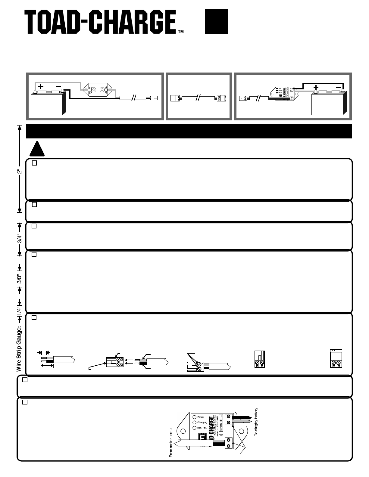
LSL Products TOAD-CHARGE User manual

TOW BAR
Towed Vehicle
Battery Charger
STEP 1 - DETERMINE WHERE TO MAKE THE MOTORHOME CONNECTIONS: Disable your motorhome's house battery
charger and solar panels before disconnecting the battery cable from the Negative post on the motorhome starting and house
batteries. Next, identify a suitable point for connecting the kit's wire harness to the Positive and Negative/Chassis Ground sides of
the motorhome starting or house batteries (either at the motorhome's battery isolator or directly to the battery posts), (NOTE:
Connecting to the house batteries has the advantage of allowing the dinghy vehicle to be recharged overnight when parked with AC
hookups. However, connecting to the starting battery(s) instead may be more convenient on some motorhomes.)
GENERAL INFORMATION — TOAD-CHARGE™ keeps the battery in your towed vehicle (or "Toad") charged while it is being towed
behind your motorhome. The kit connects between your motorhome's starting or house batteries and the towed vehicle's battery,
using the motorhome's engine to supply up to 10 amps of current to the towed vehicle's battery. The kit consists of a Charge
Controller installed in the towed (or "Dinghy") vehicle's engine compartment, a 15 Amp Circuit Breaker installed near the motorhome
starting battery, and a cut-to-length 40 or 60 foot wire harnesses with user-installed connectors.
Step-By-Step Installation Instructions
USE CARE AROUND BATTERIES — SPARKS CAN IGNITE HYDROGEN GAS. SHORT CIRCUITS CAN CAUSE BURNS OR FIRE.
CORROSIVE ACID CAN CAUSE SKIN BURNS OR BLINDNESS. USE CARE IN DRILLING HOLES NOT TO CONTACT ANY
ELECTRICAL WIRING — HAZARD OF SHOCK, FIRE, BURNS.
STEP 2 - MOUNT THE CIRCUIT BREAKER: Mount the 15 Amp Circuit Breaker next to your chosen motorhome battery
connection point, either using large nylon zip-ties or 2 sheet metal screws in 1/8" drilled holes. WARNING: DO NOT OMIT THE
CIRCUIT BREAKER, OR A FIRE HAZARD WILL RESULT!
!
©2003-2014 LSL Products All Rights Reserved
Next, split some of the white plastic covering off the surplus cable left over from STEP 3 to expose the red wire inside, and cut this
wire long enough to connect between the Circuit Breaker and your previously-chosen Positive connection point. Crimp a small
yellow ring terminal to one end before attaching it to the BATTERY terminal on the Circuit Breaker. Crimp a small, medium or large
yellow ring terminal to the other wire end before attaching it to your chosen Positive connection point.
STEP 4 - CONNECT THE MOTORHOME WIRE HARNESS: Next to the circuit breaker, remove some white plastic covering on
the wire harness to expose the Red and Black wires inside. Cut these wires just long enough to reach the Circuit Breaker (for the
Red wire) and your chosen Negative/Chassis Ground (for the Black wire). Strip approx. 3/8"" of insulation off the Red wire, crimp a
small yellow ring terminal to it, and connect it to the HARNESS terminal on the circuit breaker. Crimp a ring terminal (small, medium
or large size) to the harness Black wire before connecting it to your chosen Negative/Chassis Ground connection point.
STEP 6 - MOUNT THE CHARGE CONTROLLER: Inside your dinghy vehicle's engine compartment, Use 2 sheet metal screws or
large zip-ties to mount the Charge Controller near the vehicle's battery posts or jump start terminals. Disconnect the vehicle's battery
cable from the Negative post on the battery before proceeding.
House or
Starting
Battery(s)
RED
TOAD-CHARGE™15 AMP
CIRCUIT BREAKER
BLACK
Dinghy
Vehicle
Battery
Tow Bar Harness
Motor Home
Harness
Dinghy Vehicle
Harness
15 Amp Circuit Breaker
Charge
Controller
DINGHY VEHICLE
RED
BLACK
(See steps 1-5 below)
(See step 8 below)
(See steps 6-7 below)
STEP 7 - INSTALL THE DINGHY HARNESS: Take one
end the surplus harness wire left over from STEP 3 above,
strip 1/4" off its red and black wires before connecting them
to the MH terminals on the Charge Controller (Red wire to
MH+ terminal, Black wire to
MH–
terminal). Route the other
end of this harness from the Charge Controller to the
dinghy vehicle's front grille near a tow bar attachment
point. Cut off any excess length, leaving about a foot of
harness hanging next to the towbar.
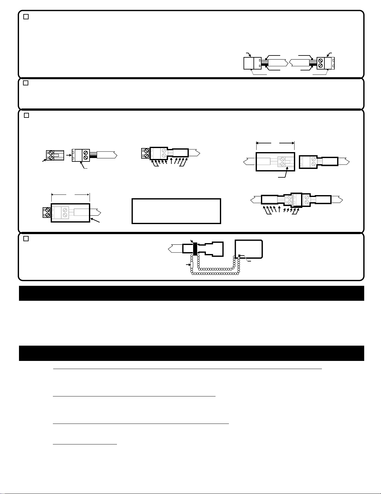
STEP 5 - INSTALL THE MOTORHOME HITCH CONNECTOR: On the motorhome hitch end of the harness, remove 3/4" of the
white plastic outer covering. Strip 1/4" of insulation off the exposed red and black wires, twisting any frayed small copper wires
back together. Next, fully insert these bare wires into one of the green FEMALE (smaller) connectors included in the kit before
tightening the connector screws to captivate the wires. (TIP: For easier wire insertion, hold the the connector with its screw heads
facing up while inserting the wires.) The Red wire goes to the connector pin marked with a red dot.
Rev.
H1+
STEP 3 - INSTALL THE MOTORHOME WIRE HARNESS: Starting next to the circuit breaker, route the wire harness rearward to
your motorhome's receiver hitch, attaching it every several feet with large zip-ties. Leave enough extra harness wire next to the
circuit breaker for making a connection to it, and to the chassis ground you identified in STEP 1 above. Leave about a foot of
harness dangling beyond the hitch, cutting off the rest.
Insert wires & tighten screws
Harness
Charge Controller
(installed in dinghy vehicle)
Attach a FEMALE connector to it,
just like in STEP 5 above. Use
another piece of surplus red and
black wire to connect the Charge
Controller to the dingy battery,
using ring terminals to connect the
wires to the dinghy battery cable
clamp bolts or jump start terminals
(Red wire to +, Black wire to –).
BLACK
RED
BLACK
RED
Female
Connector
Male
Connector
Male
Connector
Female
Connector
MOTOR HOME
Page 1 of 2
Strip 3/4"
Strip 1/4"
Harness
Female (smaller) Connector
Red Wire
Red Dot
Black Wire
Tighten Screws
After Inserting Wires
IMPORTANT:
Take care to install
the correct
connector gender!
FEMALE
MALE
(see wire strip gauge)

L S L PRODUCTS • 5804 BABCOCK RD. # 512 • SAN ANTONIO, TX 78240 • 877-257-4655 • www.LSLProducts.net
Operation & Maintenance
The green POWER light confirms that the Charge Controller is receiving DC power from the motorhome, and will turn off shortly after the
dinghy is unplugged from the motorhome. The Yellow CHARGING light confirms that the motor home is supplying sufficient voltage to
charge the dinghy battery (13.25 volts or greater), and will turn off shortly after the motorhome engine is shut off.
Periodic maintenance consists of: (1.) cleaning the connectors (a spray can of WD-40® works well for this task), and (2.) inspecting the
harness for cuts or nicks. Any connectors not in use should be covered by their protective dust caps.
STEP 9 - TEST THE SYSTEM FOR PROPER OPERATION: Re-connect the motorhome and dinghy negative battery cables to their
battery posts, mate the tow bar harness with its corresponding connectors on the dinghy vehicle and motorhome hitch, start the
motorhome engine, and confirm that the yellow CHARGING light on the Charge Regulator glows steady - If not, refer to the
TROUBLESHOOTING section below. Next, unplug all the connectors to allow installation of the shrink tubing.
STEP 8 - INSTALL THE TOW BAR WIRE HARNESS: With your tow bar attached and extended in the same manner as it would be
when towing your dinghy vehicle, take the surplus harness left over from STEP 5 and use LARGE zip-ties to attach it from one end of
the tow bar to the other (i.e., from dinghy vehicle to motor home). Cut off any excess harness, making sure to leave enough of it
dangling at both ends to reach the connectors on the motor home and dinghy vehicle under ALL driving and stowage conditions. If your
tow bar folds sideways or telescopes, make sure that it doesn't pinch the harness when folded or retracted.
Male (larger) Connectors
Red Wire
Red Dot
Black Wire
Motor Home
Side of
Tow Bar
Red Dot
Dinghy
Side of
Tow Bar
Troubleshooting - In Case Of Problems
SYMPTOM - No green POWER light (or yellow CHARGING light is flashing) when dinghy & motorhome are connected: Check for loose
wire crimp connections on the ring terminals at the motor home battery and 15 Amp Circuit Breaker, and for loose wire screws on the
Charge Controller, dinghy vehicle battery posts, and all plug-in connectors on the wire harness.
SYMPTOM - No yellow CHARGING light when motor home engine is running: Check to see if motorhome starting and/or house batteries
are heavily discharged - Since first priority is given to recharging these batteries, the voltage produced by the motorhome engine may not
be high enough to turn on the Charge Controller until these other batteries have had a chance to accept some charge.
SYMPTOM - Green POWER and Yellow CHARGING lights are alternately flashing: Indicates that the Charge Controller is not connected
to the dinghy vehicle battery. Check for loose connections on the Charge Controller and dinghy battery cable bolts.
SYMPTOM - Red REV POL light is on: Indicates reverse polarity (incorrect installation). Check for reversed wire connections at the motor
home battery posts, all 4 plug-in connectors, the Charge Controller terminals, and the dinghy battery posts.
NOTE: The kit includes several spare parts.
Please save them for future repairs.
Next, attach MALE (larger) connectors to both ends of this tow bar
harness, taking care to match the red wires with their corresponding red
dots on the connectors:
STEP 10 - INSTALL SHRINK
TUBING: Temporarily mate a spare
Female connector with the Male
connector on the motorhome end of
the tow bar wire harness:
Male Connector on
Tow Bar Harness
Shrink Tubing
Use a heat gun* to apply heat to
all areas of the shrink tubing, so
that it shrinks down to the shape
of the Male connector and harness
wire:
Slide another 2" piece of heat-shrink tubing over the
Female connector on the back of the motorhome
before mating it with the tow bar connector you
previously shrunk tubing over:
2"
Female Connector
on Back of Motorhome
Spare
Female
Connector
Cut a 2" piece of red heat-shrink tubing,
and slide it over the Male connector:
Apply heat
Remove the spare Female
connector after the tubing
cools.
*NOTE: Use the LOW (750 watt) heat gun
setting. If a heat gun is not available, use a
butane lighter or torch to GENTLY heat the
tubing – Work slowly, to avoid scorching it
before it has time to shrink.
STEP 11 - INSTALL THE CONNECTOR DUST CAPS:
Connector
Small Zip Tie
Bead Chain
Dust
Cap
Slide the open end of a bead chain through the slit in
one of the red vinyl dust caps, and then use the joiner
on the chain to connect both ends of the chain together.
Next, use a small zip tie to secure the bead chain near
one of the connectors at the end of a harness.
Repeat STEP 10 for the other tow bar and
dinghy connectors.
Slit
(see strip gauge)
Joiner
Apply heat
2"
(see strip gauge)
Male Connector on
Tow Bar Harness
Apply heat to shrink the tubing:
Repeat STEP 11 for the other 3
harness connectors, and you're
done with the installation process.
This product has a ONE YEAR warranty against defects. For service, repair parts or technical support, please contact:
Page 2 of 2
©2003-2014 LSL Products All Rights Reserved
Table of contents
Other LSL Products Batteries Charger manuals

LSL Products
LSL Products TOAD-CHARGE User manual

LSL Products
LSL Products TOAD-CHARGE K1 User manual

LSL Products
LSL Products TOAD-CHARGE User manual

LSL Products
LSL Products Mega TRIK-L-START User manual

LSL Products
LSL Products TOAD-CHARGE L1 User manual

LSL Products
LSL Products BatteReady Installation instructions