manuals.online logo
Brands
  1. Home
  2. •
  3. Brands
  4. •
  5. Ltech
  6. •
  7. Media Converter
  8. •
  9. Ltech LT-DMX-3001 User manual

Ltech LT-DMX-3001 User manual

1
LT-DMX-3001
DMX-SPI Signal Decoder Manual
LT- DMX-3001
1. Product parameter
Input voltage
Input Signal
Output signal
Decoding Channels
Output Grey Scale
DMX512 Connector
Product Dimension
Package Size
Working temperature
Weight (G.W)
DC12V~DC24V
DMX512/1990
SPI(compatible with TLS3001, TLS3002, driving IC)
512 DMX CH/unit
256 levels/CH(8bit/CH)
Standard XLR-3 Connector
L125×W52×H40mm
L135×W70×H50mm
-30 ~65
℃ ℃
300g
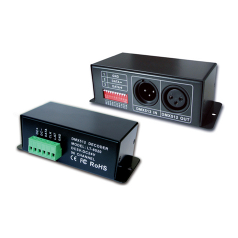
LT-DMX-3001 DMX decoder works to convert universal DMX512 signal to SPI(TTL)
signal. It can control LED lights based on Tm1803, TM1804, Tm3001, TM1812 via DMX
console.
Tm1803, TM1804, TM3001 and TM1812 are the IC with grey scale processor. It can
support 256 scale levels and only need one signal cable, which convenient for design and
installation for the LED lights. These 4 chips are widely used in LED digital lights among
LED dot light, SMD strip, LED Fence tubes, LED wall light, LED pixel screen, LED Hi-
Power spotlight , flood light, etc.
The kernel of our LED controller adopt MCU from ATMEL to ensure the LT-DMX-3001 DMX
decoder runs steady.
RoHS
COMPLIANT
warranty
3 years
ISO9001:2008
ZHUHAI LTECH ELECTRONIC TECHNOLOGY CO., LTD. WWW.LTECHONLINE.COM
LT@LTECHONLINE.COM
Tel: +86 756 620 8823 Fax: +86 756 620 8833
LT- DMX-3001 DMX512 Decoder Manual LT- DMX-3001 DMX512 Decoder Manual
LTECH LTECH
2
The Port of connecting
Power supply & LED light
2. Configuration Diagram
1 2 3 4 5 6 7 8 9 10
ONDIP
DMX signal input port
DATA
DC+
MODE L: LT-DMX-1
DMX5 12 DECOD ER
DC5V- DC24V
512 CH ANNEL
GND
3. Output Port definition
No. Silk screen Function
1
2
3
4
5
6
Power supply
input port
Output port
Connect LED
LED power supply input anode
LED power supply input cathode
Data cable
Ground wire (power supply cathode), 2 GND ports,
Only connecting 1 GND is OK.
DC+
DC-
DATA
GND
DC+
GND
Attention: The power supply DC+ cannot connect to data cable. Otherwise it will
damage the decoder and the LED’s driving IC.
4. How to set DMX address via dip switch
Figure 1
1 2 3 4 5 6 7 8 9 10
ON
0
1
OFF
ON
1, Set DMX512 original address
123567810
4
001 002 004 008 016 032 064 128 256
1.This decoder adopts Dip switch to set the address. The Dip switches from 1 to 9 are a kind of binary
value coding switches which used for setting DMX512 initial address code, The 1st is the lowest one, The
9th is the highest one. Can set 511 addresses totally.
2.DMX512 initial address is the total amount of the Dip switch 1-9, down dip switch to “ON” position, User
can get its place value, Up dip switch to “OFF” position, Its place value is 0.
Instructions
DIP
Address
LED power supply output anode
GND
M1804, TM3001 and TM1812IC can choose high or low speed when used in LED
design circuit. TM1803 only can choose low speed. Designed in low speed will get
high PWM frequency and designed in high speed can control more LED lights. The
high or low speed choosing of the decoder needs to match the light’s design gears.
Otherwise the LED light can not work. The general LED lights are designed in low-
speed mainly.
high/
low speed
9
The Decoder enter into DMX control mode automatically., when receiving DMX signal.
Like figure 1: Fun=off is high speed(upward), FUN=ON is low speed (downward)
4
1 2 3 4 5 6 7 8 9 10
ON
0
1
OFF
ON
Figure 2
3
2. T esting function:
1 2 3 4 5 6 7 8 9 10
ON
0
1
OFF
ON
The DMX decoder will be entered into self control mode automatically without DMX signal input
DIP1 DIP2 DIP3 DIP4 DIP5 DIP6 DIP7 DIP8 DIP9
Red Green Blue Yellow Purple Cyan White
Jumping
Gradual change
th th
DIP8/DIP9 at “ON” (the 8 /9 DIP swithch is dowanward) is changing mode.DIP switch 1-7 has 8 levels speed changing,
DIP 7 is the fastest speed.DIP switch 1-7 at “OFF” is speed 0
DIP1 DIP2 DIP3 DIP4 DIP5 DIP6
Speed 1
1 2 3 4 5 6 7 8 9 10
ON
0
1
OFF
ON
Speed 2 Speed 3 Speed 4 Speed 5 Speed 6 Speed 7
Like figure 4
it is color fade effect of testing function, the speed is 7.
, if several DIP switch at “ON”, it is subject to the maximum valuei.f all DIP switch at “ON”,
DIP7
Figure 3 Figure 4
5. Configuration Diagram
1. LED point source conjunction diagram
For example, Like figure 2, Set initial address to 37, Set the “1st”,”3rd “,”6th”, bit of the DIP switch
down to “1” The rest to “0” as the below figure, In this connection, the summation from 1 to 9 is 1+4+32,
Namely , The DMX512 initial address code is 37.
ZHUHAI LTECH ELECTRONIC TECHNOLOGY CO., LTD. WWW.LTECHONLINE.COM
LT@LTECHONLINE.COM
Tel: +86 756 620 8823 Fax: +86 756 620 8833
4
6. Attention
2. LED wall washer conjunction diagram
DC12 V-24V
DC12 V-24V
1
1
12
2
23
3
34
4
45
5
56
6
67
7
78
8
89
9
910
10
10
ON
ON
ON
DMX512 OUT
DMX512 OUT
DMX512 OUT
DMX512 IN
DMX512 IN
DMX512 IN
DC12 V-24V
LPD 300 1
IP- DMX
Hi- power w all was her
MODEL: DMX-1
512 CHANNEL
LPD 300 1 LPD3 001
DMX Data Input
DMX512
PC SOFTWARE
DMX512
CONTROL SYSTEM
Data C onver tor
Pow er adap ter
CONNECT POWER
SUPPLIER
Sig nal O utp ut
Inpu t Power
Pow er adap ter
Sig nal O utp ut
Inpu t Power
Sig nal O utp ut
Inpu t Power
Pow er adap ter
CONNECT POWER
SUPPLIER
CONNECT POWER
SUPPLIER
Hi- power w all was her Hi- power w all was her Hi- power w all was her Hi- power w all was her Hi- power w all was her
Output Input Output InputOutput
DATA
CLK
GND
DC+
GND
GND
DC+
DATA
1. The product shall be debugged and installed by professional persons.
2. This product is non-waterproof, please avoid the sun and rain. Put it in a water- proof box if
install outdoor.
3. Good condition of heat dissipation will prolong the working life of controller, please install the
product in a good ventilated condition.
4. Please check if the output voltage of the LED power supply comply with the voltage range of
the product.
5. The diameter of adopted cable should load enough connected LED light. Ensure a solid
connection in order to avoid triggering accident result from poor contact or cable overheat.
6. Ensure all wire connection are correct before power debugging, which is to avoid lamps to be
burnt because of wrong connection.
7. Please do not maintain it by yourself if any fault, please contact your supplier if any question.
DC12V-DC24V
MODEL: DMX-1
512 CHANNEL
GND
GND
DC+
DATA
DC12V-DC24V
MODEL: DMX-1
512 CHANNEL
GND
GND
DC+
DATA
DC12V-DC24V
7. Warranty Agreement
★ This manual only applies to this model. Ltech reserves the right to make changes without prior notice.
LT- DMX-3001 DMX512 Decoder Manual LT- DMX-3001 DMX512 Decoder Manual
LTECH LTECH
1. We provide lifelong technical assistance with this product:
A 3 year warranty is given from the date of purchase. The warranty is for free repair or
replacement and covers manufacturing faults only.
For faults beyond the 3 year warranty we reserve the right to charge for time and parts.
2. Warranty exclusions below:
Any man-made damages caused from improper operation, or connecting to excess voltage
and overloading.
The product appears to have excessive physical damage.
Damage due to natural disasters and force majeure.
Warranty label, fragile label and unique barcode label have been damaged.
The product has been replaced by a brand new product.
3. Repair or replacement as provided under this warranty is the exclusive remedy to the customer.
Ltech shall not be liable for any incidental or consequential damages for breach of any stipulation
in this warranty.
4. Any amendment or adjustment to this warranty must be approved in writing by Ltech only.
Other Ltech Media Converter manuals

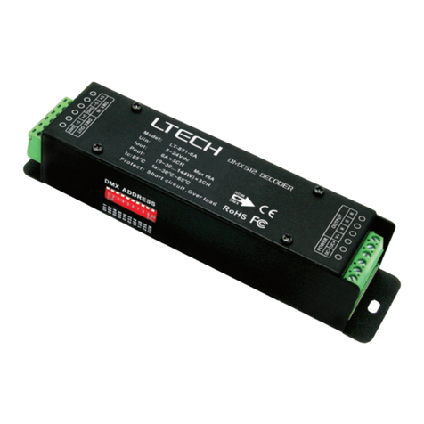
Ltech LT-853-6A User manual

Ltech

Ltech LT-853-6A User manual

Ltech LT-912-OLED User manual

Ltech

Ltech LT-912-OLED User manual

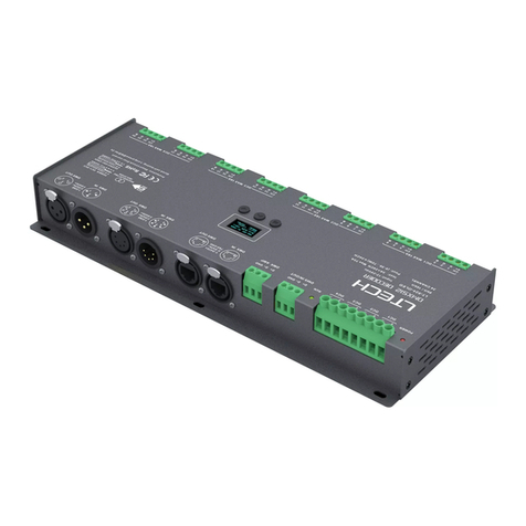
Ltech DIN-DMX-350 User manual

Ltech

Ltech DIN-DMX-350 User manual

Ltech LT-905 Operator's manual

Ltech

Ltech LT-905 Operator's manual

Ltech LT-858-5A User manual

Ltech

Ltech LT-858-5A User manual

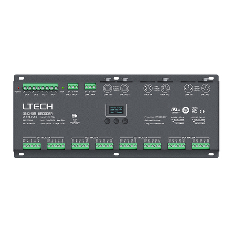
Ltech LT-932-OLED User manual

Ltech

Ltech LT-932-OLED User manual

Ltech LT-903-DIP User manual

Ltech

Ltech LT-903-DIP User manual

Ltech LT-851-5A User manual

Ltech

Ltech LT-851-5A User manual

Ltech Artnet-DMX-1 User manual

Ltech

Ltech Artnet-DMX-1 User manual

Ltech LT- 830 User manual

Ltech

Ltech LT- 830 User manual

Ltech LT-905-OLED User manual

Ltech

Ltech LT-905-OLED User manual

Ltech LT-924-OLED User manual

Ltech

Ltech LT-924-OLED User manual

Ltech LT-904 User manual

Ltech

Ltech LT-904 User manual

Ltech 2272700 User manual

Ltech

Ltech 2272700 User manual

Ltech LT-830-700 User manual

Ltech

Ltech LT-830-700 User manual

Ltech Artnet-SPI-8 User manual

Ltech

Ltech Artnet-SPI-8 User manual

Ltech SE 20 250-1000-W2B2 User manual

Ltech

Ltech SE 20 250-1000-W2B2 User manual

Ltech LT-830-350 User manual

Ltech

Ltech LT-830-350 User manual

Ltech WP-803H User manual

Ltech

Ltech WP-803H User manual

Ltech LT-830-8A User manual

Ltech

Ltech LT-830-8A User manual

Ltech Artnet-DMX-2 User manual

Ltech

Ltech Artnet-DMX-2 User manual

Ltech LT-DMX-1809 User manual

Ltech

Ltech LT-DMX-1809 User manual

Ltech LT-912 User manual

Ltech

Ltech LT-912 User manual

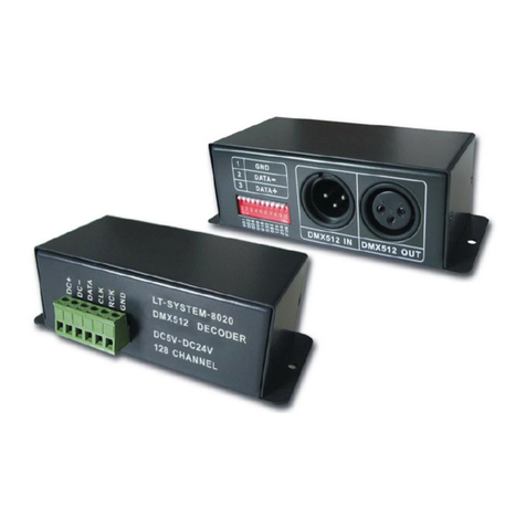
Ltech LT-DMX-8020 User manual

Ltech

Ltech LT-DMX-8020 User manual

Popular Media Converter manuals by other brands

Kramer SD-7401 user manual

Kramer

Kramer SD-7401 user manual

Panduit SmartZone PViQ Technical reference

Panduit

Panduit SmartZone PViQ Technical reference

Bustec ProDAQ 3411 user manual

Bustec

Bustec ProDAQ 3411 user manual

Atlona AT-HD120 user manual

Atlona

Atlona AT-HD120 user manual

novotechnik 4800-R Instructions for use

novotechnik

novotechnik 4800-R Instructions for use

CHD Elektroservis MXC-56 user guide

CHD Elektroservis

CHD Elektroservis MXC-56 user guide

Fairport FBS40M Operation, spare parts and service manual

Fairport

Fairport FBS40M Operation, spare parts and service manual

Konig KN-HDMICON26 manual

Konig

Konig KN-HDMICON26 manual

BARIX Exstreamer 500 install guide

BARIX

BARIX Exstreamer 500 install guide

Transition Networks M/GE-PSW-PSE-01 user guide

Transition Networks

Transition Networks M/GE-PSW-PSE-01 user guide

Extron electronics VSC 75 user manual

Extron electronics

Extron electronics VSC 75 user manual

Weidmüller IE-CS-MBGW-2TX-1COM Hardware installation guide

Weidmüller

Weidmüller IE-CS-MBGW-2TX-1COM Hardware installation guide

Polk Audio Omni P1 Setup guide

Polk Audio

Polk Audio Omni P1 Setup guide

BAPI VC3000 series Installation and operation instructions

BAPI

BAPI VC3000 series Installation and operation instructions

FUTABA MPDX-1 instruction manual

FUTABA

FUTABA MPDX-1 instruction manual

CYP CP-293 Operation manual

CYP

CYP CP-293 Operation manual

Humandata USB Series installation guide

Humandata

Humandata USB Series installation guide

Axis P7224 installation guide

Axis

Axis P7224 installation guide

manuals.online logo
manuals.online logoBrands
  • About & Mission
  • Contact us
  • Privacy Policy
  • Terms and Conditions

Copyright 2025 Manuals.Online. All Rights Reserved.