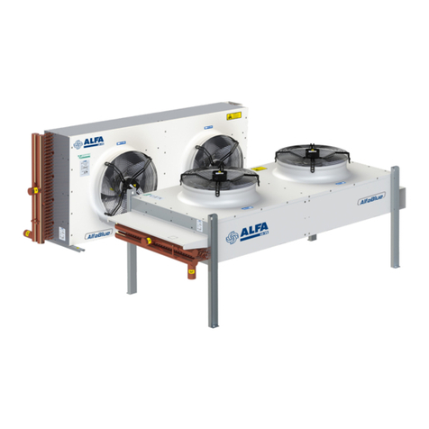
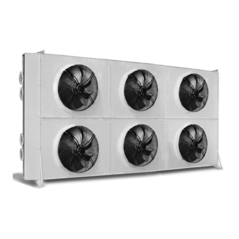
LU-VE Alfa LU-VE Alfa-V VDD User manual

ORIGINAL INSTRUCTIONS
30366474EN-03
Alfa-V VDD
Instruction manual
• Product description
• Product labels
• Transport & lifting
• Installation
• Maintenance
• Spare parts

30366474EN-03
2
Alfa LU-VE is a trademark registered and owned by LU-VE Group.
Alfa LU-VE reserves the right to change specifications without prior notification.
Index
1. Important information
1.1 Disclaimer...................................................................................................................................3
1.2 Intended use...............................................................................................................................3
1.3 Where to nd product information ..............................................................................................3
2. Product description
2.1 General information and application...........................................................................................4
2.2 Standard conguration ...............................................................................................................4
2.3 Options.......................................................................................................................................4
2.4 Code description ........................................................................................................................5
3. Product labels...........................................................................................................................5
4. Unpacking and lifting
4.1 Unit delivered by standard truck.................................................................................................8
4.2 Unit delivered in a container.......................................................................................................8
4.3 Lifting from above.....................................................................................................................10
5. Installation
5.1 Container skid removal (if present) ..........................................................................................12
5.2 Mounting dimensions ...............................................................................................................13
5.3 Feet dimensions detail .............................................................................................................13
5.4 Concrete mounting base ..........................................................................................................13
5.5 Expansion joints .......................................................................................................................13
5.6 Vibration dampers ....................................................................................................................14
5.7 Installation layout guideline ......................................................................................................15
5.8 Electrical connections...............................................................................................................16
6. Operation
6.1 Start up procedure....................................................................................................................17
6.2 Shutdown .................................................................................................................................17
7. Maintenance
7.1 Fan replacement ......................................................................................................................18
7.2 Stepping on the unit .................................................................................................................18
8. Spare parts..............................................................................................................................19

30366474EN-03
3
Alfa LU-VE is a trademark registered and owned by LU-VE Group.
Alfa LU-VE reserves the right to change specifications without prior notification.
1 Important information
1.1 Disclaimer
This Instruction Manual applies to all Alfa-V industrial dry coolers and is supplied in combination
with the Air Cooled Liquid Coolers Product Manual AHE00050. Both manuals must be carefully
examined and instructions should be followed up at all times. Alfa LU-VE does not accept liabil-
ity for any damage resulting from non-compliance to the instructions as given in the manuals and
order-related documents.
1.2 Intended use
Liquid coolers are partly completed machinery according to Machine Directive 2006/42/EC and
intended for incorporation in cooling systems. Declarations of Incorporation are available on
alfa.luvegroup.com. The units may not be put into operation until the conformity of the complete
machine or cooling system has been declared according to the following standards and directives:
• Pressure Equipment Directive 2014/68/EU
• Machine Directive 2006/42/EC
• Low Voltage Directive 2014/35/EU
• Electrical Equipment of Machines IEC 60204-1
• Electro Magnetic Compatibility 2014/30/EU
• Any applicable local or national legislation
1.3 Where to find product information
Detailed technical data for individual product models are available in order related documents,
on the product label and in product data sheets. Comprehensive technical information for all Alfa
LU-VE air heat exchanger products is available on-line on alfa.luvegroup.com. This includes:
• Product manuals
• Instruction manuals
• Product leaflets & brochures
• Product data sheets (selection software)
• Dimensional drawings
• Electrical wiring diagrams
• Certificates
Alfa LU-VE offers world-wide service and support. In case of any questions or uncertainty please
contact your local Alfa LU-VE representative. Contact addresses are available at alfa.luvegroup.
com.
Alfa-V VDD

30366474EN-03
4
Alfa LU-VE is a trademark registered and owned by LU-VE Group.
Alfa LU-VE reserves the right to change specifications without prior notification.
2 Product description
2.1 General information and application
The Alfa-V VDD series is a wide range of heavy duty dual fan row V-type dry coolers for HVAC,
refrigeration and various industrial applications such as water/glycol cooling.
For industrial applications, dry coolers are suitable for closed circuit cooling of various process liq-
uids in f.i. food, power, process and general industries. Alfa-V VDD dry coolers provide high capaci-
ties at reduced power consumption and a compact footprint.
• Capacity range (water, EN1048): 100 up to 1800 kW
• Design pressure: 10 bar. Each heat exchanger leak tested with dry air
2.2 Standard configuration
• Finned coil:
- Smooth copper tubing ø 12 and 16 mm (VDD and VDD6) or SS304 stainless steel tubing
16 mm (VDDY).
- Separate connections allow independent operation of both cooling coils.
• Fans:
-2 to 9 fan pairs, available in three fan diameters (ø 800 mm, ø 910 mm & ø 1000 mm) and dif-
ferent noise levels. ErP compliant motors with dynamically and statically balanced external rotor,
protection class IP54 according to DIN 40050 and integrated thermo contacts to provide reli-
able protection against thermal overload. AC power supplies 400/50/3, 400/60/3 and 460/60/3.
EC power supply 380-480/50-60/3.
• Casing, supports and frame made of corrosion resistant galvanized steel (class C4-H).
Separated fan sections and removable fan rings.
• Frame construction provides high rigidity for protection against vibration and thermal expansion.
• Stickers indicate fan direction and refrigerant in/out.
2.3 Options
• Fin spacing (up to 3.0 mm)
• Coil corrosion protection
- Epoxy coated aluminium fins (EP)
- F-coat treatment (FC)
- Seawater resistant aluminium AlMg (SWR)
- Industrial R-fin (RIF)
- Epoxy coated aluminium R-fin (REP)
- Seawater resistant aluminium AlMg R-fin (RSWR)
• Coil protection grid (GR)
• Spray water device kit (KW)
• Spray water system including pumping station (SWS)
• Casing coated RAL 9002 (other colors on special request)
• Container skid (SK)
• Ladder and railings
• Vibration dampers (VD)
• Expansion tank (ET)
• Special fan motors:
- Protection class IP55
- High-temperature motors
- IEC standard motors (on special request)
• Electrical options:
- Switch on/off (SW)
- EC Motors wired to a common terminal box (CBP=connection box, CBMT=connection box and
master controller+temperature signal)
- Switchboard IP54 (BS)
- AC fan step control cabinet (BST)
- EC fan speed control cabinet (ICM)
- Basic EC switchboard panel (ECCB)
30366474EN-03
5
Alfa LU-VE is a trademark registered and owned by LU-VE Group.
Alfa LU-VE reserves the right to change specifications without prior notification.
6
4
7
3
10
11
5
6
8
1 2
99
9 9
10
11
1. Centre of gravity
Forklifts can be used to lift 2 to 5 modules units
only: always place the forks under the center of
gravity.
2. Handle with care
When handling the unit, always take maximum
care.
HANDLE
WITH CARE
WITH
HANDLE
CARE
2.4 Code description
VDD SE 90 4 .1 B D 72 SK C4 * - AL 2.1 CU *
1 2 3 4 5 6 7 8 9 10 11 12 13 14 15
1 Alfa-V dry cooler (VDD=standard Cu tube,VDD6=5/8" Cu, VDDY=5/8" SS304)
2 Sound level/fan code (T=turbo, S=standard, L=low, Q=quiet, R=residential, E=EC fan motor)
3 Fan diameter (80=800, 90=910, 100=1000 mm)
4 Number of fan pairs (2 to 9)
5 Alfa-V series II
6 Tube rows code (A, B, C, D)
7 Fan motor connection (D=delta, Y=star)
8 No of circuits
9 Packing (SK=container skid)
10 Case material
11 Electrical options
12 Fin material (AL=aluminium, IF=industrial fins, SWR=AlMg, EP=epoxy coated aluminium,
FC=F-coat, RIF=industrial R-fin, REP=epoxy coated aluminium R-fin, RSWR=AlMg R-fin)
13 Fin spacing (2.0, 2.1, 2.3, 2.5, 3.0 mm)
14 Tube material (CU=copper, SS=stainless steel)
15 Options
3 Product labels

30366474EN-03
6
Alfa LU-VE is a trademark registered and owned by LU-VE Group.
Alfa LU-VE reserves the right to change specifications without prior notification.
3. Product label
Model Refer to paragraph
"Code description"
Item ID
Serial no.
Communicate these
when ordering spare
parts as they identify
the unit.
O. A. Order
Acknowledgement
number
Unit Net Weight Check before any
lifting operation to
ensure that proper
lifting tools are used.
WARNING
READ INSTRUCTION MANUAL BEFORE INSTALLATION AND
MAINTENANCE TO AVOID INJURIES OR DAMAGE
Manufacturer Manuf. Date
AIR HEX ALONTE S.R.L. - Italy 04 / 2019
Model O.A. **********
VDD*****************************
*********************************
Item ID **************
Serial no. **************
Unit Net Weight 3681 Kg ±5%
Sn
Motorfan data
Vn 3~380/480V
f 50/60Hz
Country of origin Italy
i
EXAMPLE
WARNING
READ INSTRUCTION MANUAL BEFORE INSTALLATION AND
MAINTENANCE TO AVOID INJURIES OR DAMAGE
Manufacturer Manuf. Date
AIR HEX ALONTE S.R.L. - Italy
04 / 2019
Model O.A. ***********
VDD**********************************
**********************************
Item ID ***************
Serial no. ***************
Sn
Material CU
PED Category Art. 4.3
Max DN 80
Fluid Group 2
Coil Ts +110/-60 °C
Ps 10 bar
Pt 15 bar
Test Date 04-2019
EXAMPLE
4. Product label - coil
Model Refer to paragraph
"Code description".
Item ID
Serial no.
Communicate these
when ordering spare
parts as they identify
the unit.
Material Tube material
PED Category According to PED
Max DN Maximum diameter
of the distributor tube
Fluid Group According to PED
Coil Ts Range of operating
temperatures for the
coil
Ps Design pressure
Pt Test pressure
Test date Date on which the
coil has been pres-
sure tested in the
factory

30366474EN-03
7
Alfa LU-VE is a trademark registered and owned by LU-VE Group.
Alfa LU-VE reserves the right to change specifications without prior notification.
5. Fan direction
Sticker indicates fan rotation direction.
9. Lifting lug
Use all marked lifting lugs when lifting from
above.
6. Electrical warning
Electrically powered component. Switch off
power supply before any maintenance or instal-
lation activity.
41103043SP
Spare part item number
8. Fan motor
Fan motor item number.
10. & 11. In/Out
Refrigerant connections inlet and outlet.
IN
OUT
Grounding
Whenever electrical components supplied by
Alfa LU-VE have this sticker, is mandatory to
ground them. The yellow/green grounding wire
must be left longer than the others, to ensure
that it is the last one to be detached from the
terminals in the event of the cable being pulled
off. Grounding is designed for the electrical
equipment supplied with the unit and is not to
be intended as protection from external sourc-
es.
7. Moving parts
Warning: moving parts.
Switch off power supply before any mainte-
nance or installation activity.

30366474EN-03
8
Alfa LU-VE is a trademark registered and owned by LU-VE Group.
Alfa LU-VE reserves the right to change specifications without prior notification.
4 Unpacking and lifting
Always follow guidelines and instructions as given in the air cooled liquid coolers product manual
AHE00050.
Before lifting the unit, check the weight stated on the name plate, located on the inlet connection
side. Verify that the lifting equipment supports at least the unit weight plus 10%.
• Forklifts can be used only with 2 to 5 modules units.
• When forklifts are used, forks must be longer than 2.5 m for safe lifting and be fully inserted
under the unit.
• Unit shall be lifted only when empty.
Alfa-V VDD dry coolers can be delivered either on standard trucks or in containers.
4.1 Unit delivered by standard truck
The procedure below applies to the unloading of units delivered on standard trucks.
2-5 fan pairs unit:
can be unloaded from the side of the truck with
the use of a forklift.
6-9 fan pairs unit:
shall be always lifted from above.
Follow the procedure described in paragraph
"Lifting from above" for 6-8 modules unit.
9 fan pairs units are equipped by default with the
container skid and should be unloaded follow-
ing the procedure described in paragraph "Unit
delivered in a container" even if they are deliv-
ered by standard truck.
4.2 Unit delivered in a container
In case of container delivery, container skid option is to be selected in order to facilitate the loading
and unloading operations. In case of 9 modules unit, skid is installed by default. Follow the proce-
dure below to unload the unit:
• Remove any obstacle to allow the skid sliding out of the container.
• Ensure the truck is stopped.

30366474EN-03
9
Alfa LU-VE is a trademark registered and owned by LU-VE Group.
Alfa LU-VE reserves the right to change specifications without prior notification.
A
With forklift A, support the unit weight and pull it
slowly out of the container. The unit must remain
on the container floor for at least 1 m.
The space between the unit and the roof of the
container is reduced. Contact with the roof can
cause damage to the unit.
A
B
With a second forklift (identified by letter B),
insert the forks (under the centre of gravity) and
slightly lift the unit.
Remove hooks and chains and drive away with
forklift A.
B
Slowly drive forward with the truck until the unit
is completely outside the container.
A
Fix the chain to a forklift (identified by letter A) and the hooks in the skid holes.
2-5 fan pairs unit

30366474EN-03
10
Alfa LU-VE is a trademark registered and owned by LU-VE Group.
Alfa LU-VE reserves the right to change specifications without prior notification.
6-9 fan pairs unit
With forklift A, support the unit weight and pull it
slowly out until all the lifting lugs are outside the
container. The unit should remain on the con-
tainer floor for at least 1 m.
The space between the unit and the roof of the
container is reduced. Contact with the roof can
cause damage to the unit.
Attach all the lifting lugs to the crane hoisting
beam following the procedure described in para-
graph "Lifting from above".
When the crane holds up the unit, remove forklift
A. Slightly lift the unit and slowly drive forward
with the truck until the unit is completely outside
the container.
A
> 65°
> 65°
DETAIL A
A
90° 90°
4.3 Lifting from above
Verify that lifting lugs are safely fixed to the unit
and have no signs of damage. Attach the belts
or hooks only to the lifting lugs as shown in the
drawing on the next page.
Angle of chains as shown for all models.
Load on the lifting chains shall be equally distrib-
uted on all the lifting points. If one chain is not
fully loaded another chain will be extra loaded.
This is not allowed.
A

30366474EN-03
11
Alfa LU-VE is a trademark registered and owned by LU-VE Group.
Alfa LU-VE reserves the right to change specifications without prior notification.
2 MOD
4 FANS
3 MOD
6 FANS
4 MOD
8 FANS
5 MOD
10 FANS
6 MOD
12 FANS
7 MOD
14 FANS 8 MOD
16 FANS
9 MOD
18 FANS

30366474EN-03
12
Alfa LU-VE is a trademark registered and owned by LU-VE Group.
Alfa LU-VE reserves the right to change specifications without prior notification.
5 Installation
Always follow guidelines and instructions as given in the liquid coolers product manual AHE00050.
5.1 Container skid removal (if present)
Container skid option is selected in order to facilitate loading and unloading operations. 5 fan pair
units container skids have two additional feet which can be recognized because above them there
is no coil support, as shown in the picture.
Container skid (included the additional feet, if present) shall be removed before installation.
Container skid components are connected to the unit by means of screws, as highlighted below. To
remove the skid and the additional support feet it is needed to slightly lift the unit.
coil
support
additional
feet

30366474EN-03
13
Alfa LU-VE is a trademark registered and owned by LU-VE Group.
Alfa LU-VE reserves the right to change specifications without prior notification.
5.2 Mounting dimensions
Drawings showing all required mounting and liquid connection dimen-
sions are available for download on alfa.luvegroup.com.
5.3 Feet dimensions detail
Feet dimensions are identical for all models.
Avoid any lateral torque on the feet when fixing the unit.
Fixing holes can be used to fix the unit to the ground or to a beam structure and for the installation
of vibration dampers.
5.4 Concrete mounting base
To avoid oxidation of the equipment feet, it
is strongly recommended to mount the heat
exchanger on concrete mounting bases. One
base for each foot. Base minimum dimensions
are 100 mm height and 260 mm width.
5.5 Expansion joints
Alfa LU-VE recommends the installation of
expansion joints on both inlet and outlet con-
nections. Expansion joints are elastic elements
which, if properly installed, absorb the thermal
expansions of the tubing. Expansion joints are
also helpful in order to reduce vibrations in the
piping.
Dimensional drawings
2280
80
20.5
160
Fixing hole
& Vibration damper
160
80
1740

30366474EN-03
14
Alfa LU-VE is a trademark registered and owned by LU-VE Group.
Alfa LU-VE reserves the right to change specifications without prior notification.
5.6 Vibration dampers
For active and passive isolation of vibrations and reducing noise transmission, Alfa LU-VE strongly
recommends the installation of vibration dampers. Installation of vibration dampers must be carried
out before positioning the unit. Vibration dampers are to be positioned between the unit feet and the
mounting base with the supplied M16 screw.
Fan pairs Vibration dampers
2 4
3 4
4 6
5 8
6 8
7 8
8 10
9 12
4
51,5
168
150
M 16
132
168
12,5
Isolating material natural rubber,
hardness 60° Sha.
Picture shows an installation example using
threaded bar, nut, grower washer, washer and
locknut (not supplied).
This way vibration dampers can be used to
make the cooler level adjusting the locknut. This
is particularly useful with long units or irregular
basement.

30366474EN-03
15
Alfa LU-VE is a trademark registered and owned by LU-VE Group.
Alfa LU-VE reserves the right to change specifications without prior notification.
5.7 Installation layout guideline
Ensure installation is such that the following conditions are met:
• Place the unit outdoor in a such way that it can be monitored from all sides at all times.
• Ensure that sufficient space is available for maintenance.
• Verify the structures supporting capacity regarding the weight of the unit(s), including the liquid.
Floor mounted
Single unit
Two or more units
The unit spacings shown above are default values. If the unit(s) is (are) lifted from the ground, dis-
tances might be reduced. The 1000 mm shown above refer to the unit base and not necessarily to
the ground. In case of doubt, to determine optimal unit spacing for specific conditions on site please
contact your Alfa LU-VE representative for advise.
L/2 L/2
< 1000
< 1000
L/2
< 1000
L L/2
< 1000
L
L

30366474EN-03
16
Alfa LU-VE is a trademark registered and owned by LU-VE Group.
Alfa LU-VE reserves the right to change specifications without prior notification.
Platform for two to six units
Number of fan pairs
2, 3 4, 5, 6 7, 8, 9
H ≥ (N-1)/2 (N-1)/1.2 N-1
d ≥ L/2 L/2 L/2
h ≤ (N-1)/2 (N-1)/1.2 N-1
N= number of units on the platform.
All three conditions (H, d, h) shall be met. Contact Alfa LU-VE in case a different lay out is required.
Special care should be taken in particular circumstances, such as:
• When installation site is exposed to strong winds.
• When walls with different configuration or heights than the ones shown in the previous pictures
are present.
• When more than 6 units are installed on a single platform.
• When severe environmental loads (e.g. earthquakes) are likely to affect to the unit.
In these cases contact your local Alfa LU-VE representative for support.
5.8 Electrical connections
The following data determine which connection diagram is to be selected and respected for electri-
cal installation:
• Heat exchanger model indication
• Fan motor type
• Electrical options
Electrical connection diagrams are available for download on
alfa.luvegroup.com. When in doubt always contact your local Alfa LU-VE
representative for assistance.
h
L
h
d
d
H
Electrical connections

30366474EN-03
17
Alfa LU-VE is a trademark registered and owned by LU-VE Group.
Alfa LU-VE reserves the right to change specifications without prior notification.
6 Operation
6.1 Start-up procedure
The following procedure is to be respected at every system start-up.
• Close the liquid-in valve and open the liquid-out valve.
• Open unit vent plug and then fill the unit while venting.
• When all air has been discharged from the liquid circuit, close unit vent plug.
• Start liquid pump.
• Open system inlet valve slowly until the appropriate liquid flow is reached.
• Verify there are no leaks in the liquid circuit and connections.
• Switch on fan power supply.
• Start the fans and verify fan direction.
• After some operating time, check the absence of air in the liquid circuit (vent if needed) and
verify that current absorbtion does not exceed the value as given in the technical specifications.
6.2 Shutdown
If the unit requires emptying for maintenance, system shutdown or dismounting, proceed as follows:
• Stop liquid supply and switch off electrical power supply.
• Make sure neither liquid nor power supply can be resumed accidentally or unexpectedly.
• Close liquid-in and liquid out valves.
• Install a proper hose at the drain valves. Open venting and draining valves. Attention: fluid may
be hot.
• Make sure all drained liquid will be collected in a suitable vessel.
• Compressed air helps to drain in less time. Compressed air shall be oil free.

30366474EN-03
18
Alfa LU-VE is a trademark registered and owned by LU-VE Group.
Alfa LU-VE reserves the right to change specifications without prior notification.
7 Maintenance
Ensure complete electrical isolation before performing any maintenance activity and always follow
guidelines and instructions as given in the air cooled liquid coolers product manual AHE00050.
7.1 Fan replacement
• Open the connection box. Disconnect fan cabling.
• Unscrew fixing bolts and remove old fan.
• Mount new fan assembly in identical position. Remount fasteners. Use an anti-corrosion coating
like Geomet or comparable when remounting using new fixing bolts.
• Restore the electric connections (water trap as shown).
• Check for correct fan direction.
7.2 Stepping on the unit
If for maintenance purposes it is required to step on the on the unit, always wear safety shoes. It is
not allowed to step on the unit while it is working. Proper protection against falling shall be arranged
with railings and safely fixed ladders. If the units do not have railings a safety device that prevents
falling shall be used. Never step on the fan grids and on the liquid connections. It is not allowed to
step outside the areas highlighted in the example below.
= walkable areas

30366474EN-03
19
Alfa LU-VE is a trademark registered and owned by LU-VE Group.
Alfa LU-VE reserves the right to change specifications without prior notification.
8 Spare parts
Spare parts for Alfa-V VDD
①Fan
②Switch on/off
③Switchboard
④Vibration damper
⑤Protection grids (available on request)
Contact your local Alfa LU-VE representative for spare parts order and assistance.
②
③
④
⑤
①

alfa.luvegroup.com
Table of contents
Other LU-VE Air Conditioner manuals

LU-VE
LU-VE FHD Series Technical specifications

LU-VE
LU-VE NHI Series User manual

LU-VE
LU-VE SHL Series Technical specifications

LU-VE
LU-VE F27HC User manual

LU-VE
LU-VE BMA Technical specifications

LU-VE
LU-VE SF27HC User manual

LU-VE
LU-VE Alfa LU-VE Optigo CS User manual

LU-VE
LU-VE Alfa LU-VE AlfaBlue Junior AG User manual

LU-VE
LU-VE F27HC User manual

LU-VE
LU-VE ALFA Optigo SFMS User manual