LUBE EGM-50TH-10S User manual

L-0403-2E
Motorized Intermittent Grease Pump
EGM-50TH-10S
INSTRUCTION
MANUAL
LUBECORPORATION
・ For your safety, read and understand this manual
thoroughly before handling the pump.
・ Keep this manual at a designated place for easy
access at all times.

1
Introduction
System Application
This Motorized Intermittent Grease Pump Series
"EGM-50TH-10S" is designed to lubricate each point on a
machine by delivering a relatively small amount of grease
through a metering valve.
Do not use this system for any other purposes.
Marks used in Manual
In this Manual, safety precautions are provided using the
marks below in order to prevent accidents which might
cause injuries to human bodies. Be sure to carefully read
these safety precautions to understand the contents
thoroughly before handling the pump.
In addition to the above, the marks below will also appear in
this Manual. Please read the following explanation in order
to handle the pump correctly.
Indicates referential information or points to
which special attention should be paid while
handling the pump. If ignored, the pump and/or
the machine could be damaged.
Indicates referential information or points
which are helpful for handling the pump.
Indicates a reference clause.
Indicates a potentially hazardous
situation which, if ignored, could result
in death or serious injury.
Indicates a potentially hazardous
situation which, if ignored, may result
In minor or moderate injury.
WARNING
CAUTION

2
Questions/Contacts
If any question or doubt arises concerning the contents of
this Manual, please contact the following.
Changes in Specifications
Details of all illustrations and specifications in this Manual
are subject to change without prior notice for improvement
and development of the pump.
Resale or Leasing
At the time of resale, leasing out or lending out the pump to
the third party, make sure to include with the pump all the
manuals and any other documents supplied with the pump.
Disposal of Pump/Grease
Make sure to dispose pump or grease as designated by
National laws and/or local regulations.
■ Japan
LUBE Corporation
(LUBE Global Center)
4-2-1, Anotsudai, Tsu-shi, Mie-prer, 514-0131
TEL: 059-253-3980 FAX: 059-253-3981
■ China
LUBE LUBRICATING SYSTEM (SHANG HAI) CO.,
LTD
C, 3F, 88 Taigu Road, Waigaoqiao Free Trade Zone,
Shanghai TEL: 021-5868-3818 FAX: 021-5868-3880
■ U.S.A
LUBE USA, Inc.
1075 Thousand Oaks Blvd, Greenville, SC 29607
TEL: 800-326-3765 FAX: 864-242-1652

3
Table of contents
Introduction ················································································· 1
Table of contents ··········································································· 3
1.Safety Precautions ······································································ 4
1-1 Basic safety precautions ························································· 4
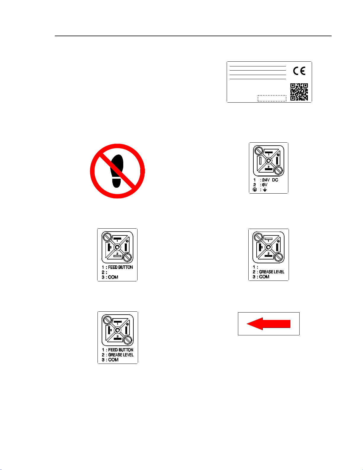
1-2 Labels················································································· 5
1-2-1 Type of labels ··································································· 5
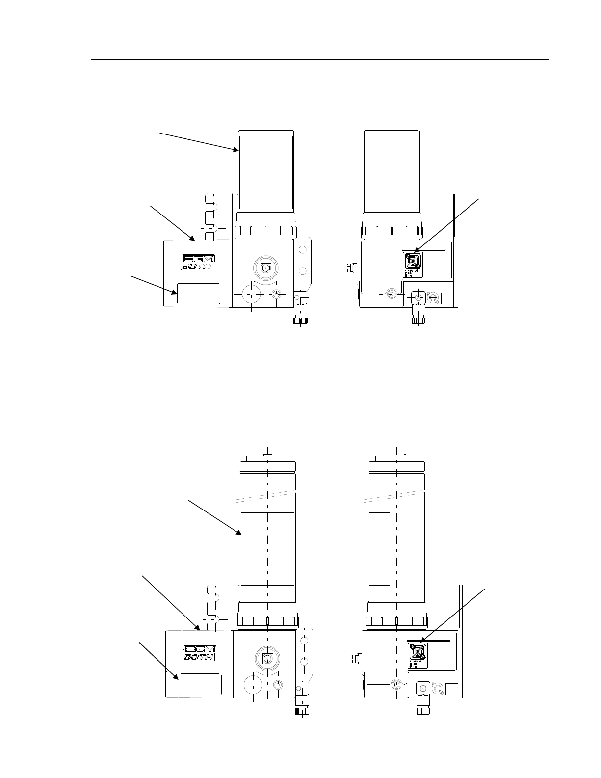
1-2-2 Location of labels ······························································ 5
2.Specification and Outline ····························································· 7
2-1 Specification ······································································ 10
2-2 Name of each component ······················································ 11
2-3 Repair parts ······································································ 14
3.Installation ············································································· 15
3-1 Environmental requirement ················································· 15
3-2 Mounting unit ···································································· 15
3-3 Wiring ·············································································· 17
3-3-1 DIN connector wiring diagram ·········································· 18
3-3-2 DIN connector connection procedure ·································· 19
3-4 Tubing ·············································································· 21
4.Setting of Timer on Machine ······················································· 22
5.Refilling Grease ······································································· 23
5-1 Grease ·············································································· 23
5-2 Replacement of grease cartridge (for the cartridge type only) ······ 23
5-3 Grease replenishment method (for the tank type only) ··············· 25
6.Maintenance ············································································ 26
6-1 Bleeding ············································································ 26
6-2 Replacement of repair parts ·················································· 27
6-2-1 Replacement of pumping unit ··········································· 27
6-2-2 Replacement of relief unit ················································ 28
6-2-3 Replacement of filter ······················································· 29
6-3 Troubleshooting ································································· 32
Appendix. Grease contamination: Causes and measures ····················· 35

4
1. Safety Precautions
1-1 Basic safety precautions
1-2 Labels
The following labels are affixed on the pump.
If any label gets damaged or becomes illegible,
contact LUBE immediately. A new one will be
supplied at your own cost.
• Carefully read this Manual and understand
the contents before handling the pump.
• Keep this Manual at a designated place for
easy access at all time.
• This pump is handled by only personnel who
have the knowledge and skill of its
installation and adjustment.
• Never modify or change this pump without
prior permission from LUBE.
• Strictly observe the instructions on the labels
affixed to the pump.
WARNING
CAUTION

5
1-2-1 Type of labels
(1) Logo (for type 7C) (2) Specification, Serial
(3) "Do not step on" label (4) Wiring (Power supply)
(5) Signal line (for type FB) (6) Signal line (for type L)
(7) Signal line (for type LFB) (8) Arrow label
VOLTAGE DC24V
RATED CURRENT 1.5A
DIS.PRESSURE 10MPa
DIS.VOLUME 10mL/min
MODEL
CODE No.
SERIAL No.
EGM-50TH-10S-7C-LFBD
101500
********
CLOSE

6
(9) Refill nipple label (10) Caution label (for types 2C,
4C, and 7C)
(11) Caution label (for type 3P) (12) Caution label (for type 8P)
補給用ニップル
REFILL NIPPLE

7
1-2-2 Location of labels
• EGM-50TH-10S-2C-D
• EGM-50TH-10S-4C-D
(2)
(3)
(10)
(2)
(3)
(10)
(4)
(4)

8
• EGM-50TH-10S-7C-D, EGM-50TH-10S-7C-LD
EGM-50TH-10S-7C-LFBD
• EGM-50TH-10S-3P-D
H
L
補給用ニップル
REFILL NIPPLE
(1)
(2)
(3)
(4)
⑧
(10)
(2)
(3)
(11)
(6) (LD)
(7) (LFBD)
(4)
(9)

9
H
L
補給用ニップル
REFILL NIPPLE
• EGM-50TH-10S-8P-D
(2)
(3)
(12)
(4)
(9)

10
2. Specification and Outline
2-1 Specification
* For specialty products, refer to the drawings.
Item Specification
Rated voltage 24 VDC±10%
Starting current 3.0 A
Rated current 1.5 A (at 25°C)
Motor lock current 4.4 A
Pump
Discharge amount 10 mL/min
Discharge pressure 10 MPa
Cartridge and tank
Dedicated 200 mL cartridge
Dedicated 400 mL cartridge
Dedicated 700 mL cartridge
Tank 3P (260 mL)
Tank 8P (800 mL)
Motor life 1,500 hours
* NLGI 00 is 500 hours
Solenoid life 3 million times
Manual switch
(type 7C-LFBD
only)
Maximum operating
voltage 24 VDC
Maximum operating
current 3 A (Inductive load)
Contact type A-contact
Grease level
switch
(type 7C-LFBD
only)
Maximum operating
voltage 24 VDC
Maximum switching
current 0.5 A
Contact type A-contact
Protection class IP54 Category2
Overseas standards CE standards

11
42.5 25
27
173
104 10
92.5 25
92-
2-φ9
133
207
12.5
19
43
42.5 25
27
92.5 25
92-
2-φ9
133
12.5
173
104 10
1919
43
380
2-2 Name of each component
• EGM-50TH-10S-2C-D
• EGM-50TH-10S-4C-D
Caution label
Cartridge cover
(Mounting hole)
Pump flange
Discharge port (Rc1/8)
Air bleeding valve
Caution label
Cartridge cover
Pump flange
Discharge port (Rc1/8)
Air bleeding valve
Pumping unit
Relief unit
Pumping unit
Relief unit DIN connector
(24 VDC input) with LED
DIN connector
(24 VDC input) with LED
(Mounting
hole)

12
42.5 25
27
179
16104
92.5 25
92-
2-φ9
133
225.5
12.5
19
92.5 25
42.5 25
27
92-
104
173
10
238
133
(10.5)
2-φ9
12.5
19
H
L
43
補給用ニップル
REFILL NIPPLE
• EGM-50TH-10S-7C-D, EGM-50TH-10S-7C-LD
EGM-50TH-10S-7C-LFBD
• EGM-50TH-10S-3P-D
Caution
label
Tank 3P
(Mounting hole)
Pump flange
Air bleeding valve
Refill nipple
Discharge port (Rc1/8)
Pumping unit
Relief unit
Caution label
Cartridge cover
(Mounting hole)
Pump flange
Air bleeding valve
DIN connector
(24 VDC input) with LED
DIN connector (signal output)
Discharge port (Rc1/8)
Pumping unit
Relief unit
Logo label
Manual switch
DIN connector
(24 VDC input) with LED

13
H
L
92.5 25
42.5 25
27
92-
2-φ9
104
262.5
175
133
(8.5)
12.5
19
43
12
補給用ニップル
REFILL NIPPLE
• EGM-50TH-10S-8P-D
Caution label
Tank 8P
(Mounting hole)
Pump flange
Air bleeding valve
Refill nipple
Discharge port (Rc1/8)
Pumping unit
Relief unit
DIN connector
(24 VDC input) with LED

14
2-3 Repair parts
1. Repair parts set (539461)
■ Pumping unit (φ3.5)
For the replacement procedure, refer to "6-2 Replacement of
repair parts."
■ Relief unit
For the replacement procedure, refer to "6-2 Replacement of
repair parts."
■ Special tool for replacing repair parts
2. Filter
For the replacement procedure, refer to "6-2 Replacement of
repair parts."
For 7C-LD and 7C-LFBD
(531402)
For 7C-D
(531403)
G3/4
M14×1
1 Punch
Mark

15
3. Installation
3-1 Environmental requirement
Be sure to use this in the following environment
• Ambient temperature: 0–+50 C
• Humidity: 35–85%RH
3-2 Mounting unit
Make sure to fix the pump firmly. Insufficient
mounting of the pump could fall itself and cause
injury.
Be sure to fix the pump against the vertical and
flat surface, which can sustain its weight
sufficiently. Mount and fix the pump firmly using
four (4) M8 bolts through φ9 holes.
LUBE recommends anti-vibration
rubber to be applied when the pump is
exposed to vibration.
Be sure to allow necessary space as marked in the
chart below for operation and maintenance
around the pump.
CAUTION

16
■ Pump weight and necessary space
Pump Model Weight*(kg)
Necessary space (mm)
EGM-50TH-10S-2C-D 2.1 A:150, B:200
EGM-50TH-10S-4C-D 2.1 A:350, B:200
EGM-50TH-10S-7C-D 2.2 A:250, B:200
EGM-50TH-10S-7C-LD
EGM-50TH-10S-7C-LFBD
EGM-50TH-10S-3P-D 2.2 A:250, B:200
EGM-50TH-10S-8P-D 3.3 A:300, B:200
The weight of grease is excluded
B
B
A

17
3-3 Wiring
For the power supply, use a 24-VDC stabilized power
supply.
For wiring, see the figure below. Make sure that the
positive (+) and negative (-) terminals are connected
correctly. If the positive (+) and negative (-) terminals
are connected incorrectly, the pump will not operate.
If an external lead wire from the 24-VDC power supply
is likely to come in contact with your hand, machine
exterior or any other surrounding object, use an
insulated wire of less than 30 m.
The LED of the DIN connector (24 VDC input) lights when the pump starts.
Only qualified personnel for electrical work should
connect wiring.
EGM-50TH-10S DIN connector
24 VDC input (with LED)
Used wire outer diameter: φ4.5 to 6 mm
(Lead wire sectional area: 0.75 mm2 max)
Signal output
Used wire outer diameter: φ4.5 to 6 mm
(Lead wire sectional area: 0.75 mm2 max)
WARNING

18
3-3-1 DIN connector wiring diagram
Wiring diagram
• EGM-50TH-10S-2C-D, EGM-50TH-10S-4C-D, EGM-50TH-10S-7C-D,
EGM-50TH-10S-3P-D, EGM-50TH-10S-8P-D,
• EGM-50TH-10S-7C-LD
• EGM-50TH-10S-7C-LFBD
1
2
24VDC(+)
0V(-)
1
2
3
COM
グリースレベルスイッチ
手動スイッチ
1
2
3
COM
グリースレベルスイッチ
1
2
24VDC(+)
0V(-)
1
2
24VDC(+)
0V(-)
Grease level switch
Manual switch
Grease level switch

19
3-3-2 DIN connector connection procedure
Step 1: Remove the DIN connector from the pump body.
Step 2: Remove the screw from the DIN connector, and then remove the terminal
with a flat-head screwdriver.
Step 3:
Step 4: Connect wires.
Strip the cable end and wires (25 mm of cable sheath and 5 mm of wire sheath),
and then insert the cable end through (1) a tightening gland, (2) a gland washer,
(3) a gland gasket, and (4) a connector cover.
Remove the screw. Insert a flat-head screwdriver in the point marked
by "▲," and then pull the terminal out.
(4)
(3)
(2)
(1)
Untighten the terminal screw with a flat-head
screwdriver.
Tighten the stranded wire.
Wire
S
tranded wire
Table of contents
Other LUBE Water Pump manuals
Popular Water Pump manuals by other brands

Graco
Graco Husky 307 Instructions-parts list

Simplex
Simplex G6 Series Reference

Goulds
Goulds Redjacket series Installation, operation and maintenance instructions

Edwards
Edwards EDS 200 instruction manual

GORMAN-RUPP
GORMAN-RUPP SUPER T SERIES Installation, operation and maintenance manual

DAB
DAB NOVA UP MAE Series Instruction for installation and maintenance