LUCAS CONTROL CE010-153 User manual

Réf. : CE010-153(U)
As of series n° 100419 O 1801
CONTROL CE010-153
(Telescopic Raptor)

I –General malfunction: no light comes on -1/2
SERVICE MANUAL SHEET
Reference:
00 01 MR 86
I –General Malfunction: No light comes on
T10 Telescopic handler’s electrical power supply test
Condition:
oPlug between the machine and the telescopic handler disconnected.
oTelescopic handler in operation (in order not to be disturbed by the connections after
contact).
Mean of control:
oVoltmeter in direct current.
Process:
oMake sure that the power supply U=13Vcc ±1 at the lift truck plug terminals.
Résultat :
Result
Observation
Action
0 Vcc
Power supply problem
on telescopic handler.
Repair the telescopic
handler’s electrical
power supply.
+ 13 Vcc ±1
Power supply is ok.
Test ok, go on with
the tests.
- 13 Vcc ±1
Change of polarity.
Repair the telescopic
handler’s electrical
power supply.
The control box doesn't
switch on when the M
button is pressed
Telescopic handler’s
electrical power
supply test
Board electrical
power supply test
Repair telescopic handler’s
power supply
Act according to the test conclusions
Control at fault
See Chap. II –Malfunction of a controlled
hydraulic function: Main control at fault
T10
Bad
Bad
Good
Good
T11

I –General malfunction: no light comes on -2/2
SERVICE MANUAL SHEET
Reference:
00 01 MR 86
T11 Board’s electrical power supply test
Condition:
oControl box open and switched on.
oPlug between the machine and the telescopic handler is connected.
oTelescopic handler in operation (in order not to be disturbed by the connections after contact)
Mean of control:
oVisual
Process:
oCheck the state of the 4 control leds inside the control box (Led INV, led ALIM, led FUSE 12V, led FUSE
5V)
Result:
State of the Leds: Led ON.
Led OFF.
Led INV
Led ALIM
Led FUSE 12V
Led FUSE 5V
Observation
Action
Case 1
Power supply OK.
Test OK, go on with the tests.
Case 2
Change of polarity.
Check the complete line (cable, plug, telescopic
handler’s power supply,…).
Case 3
No electrical power supply.
Case 4
Motherboard faulty.
Change the motherboard.
Case 5
Overconsumption.
Resettable fuses heat up.
Go on with the following test.
1- Disconnect the plug between the machine and the telescopic handler,
2- Disconnect the whole outputs (electrovalves and auxiliary boards),
3- Connect the telescopic handler’s electrical power supply again,
4 –Check the state of the control Leds.
Led INV
Led ALIM
Led FUSE 12 V
Led FUSE 5V
Observation
Action
Case 5.1
Motherboard is not at
fault.
External short circuit
Reconnect the outputs and the boards one by one until
you find out the one which is at fault.
Repair or replace it
Case 5.2
Motherboard is at fault.
Replace the board (follow the procedure here after).
Be careful :
The fault on the board is certainly due to an external short-circuit (output –auxiliary board).
During replacement you should first only connect the inputs (power supply –handle) and start-up.
Then you must reconnect the outputs and the auxiliary boards one by one and check for each that they do not blow fuses
(Led FUSE goes off and fuses heat up).
Then return to the case 5.1.
This procedure must be respected so that the new board is not damaged.

II –Malfunction of a controlled hydraulic function: the main control is faulty -1/4
SERVICE MANUAL SHEET
Reference:
00 01 MR 87
II - Malfunction of a hydraulic function
Main CONTROL is at fault.
Prior checks:
Make sure that the electrical power supply is ok.
(Chap. I-General malfunction: No light comes on)
The controlled function does
not react when the
button(s) is/are pressed.
Control operation
external test
T20
Bad
Button test
The main control is not faulty.
Continue to the chap.
III –Malfunction of a controlled hydraulic
function: Fault due to the electrovalves.
Replace the
faulty
buttons
Control cable test
Replace the
control or the
cable or the
plug
Bad
Bad
Good
Good
Replace the
control
Bad
Good
Replace the motherboard
T22
T23
T24
Control
electrical
power supply
test
Connection faulty.
Good
Power supply faulty
T21
Control board test
Good

II –Malfunction of a controlled hydraulic function: the main control is faulty -2/4
SERVICE MANUAL SHEET
Reference :
00 01 MR 87
T20 External test : control operation
Condition:
oPlug between the machine and the telescopic handler connected.
oTelescopic handler in operation (in order not to be disturbed by the connections after
contact).
oControl box switched on in normal operating mode.
Mean of control:
oVisual.
process:
oInvolves checking that the green « ON » pilot light on the front side of the control box flashes
when a button is pressed. This test must be performed for all the buttons one after the other.
Résult:
oThe test is considered « OK » if the green pilot light flashes for ALL the buttons.

II –Malfunction of a controlled hydraulic function: the main control is faulty -3/4
SERVICE MANUAL SHEET
Reference:
00 01 MR 87
T21 Control electrical power supply test
Condition:
oPlug between the machine and the telescopic handler connected.
oTelescopic handler in operation (in order not to be disturbed by the connections after
contact).
oControl box switched on in normal operating mode and open.
Mean of control:
oVisual.
Process:
oInvolves checking that the control power supply control led lights up.
oInvolves checking that the control’s 3 wires are properly connected inside the control box +
connecting plugs (machine and telescopic handler).
Résult:
oIf the control’s power supply control led does not light up the motherboard is faulty and you
have to replace it (make sure before that the motherboard’s electrical power supply is ok).
oIf the control’s cables are connected wrongly please connect them again.
oIf no fault is found out go on with the tests.

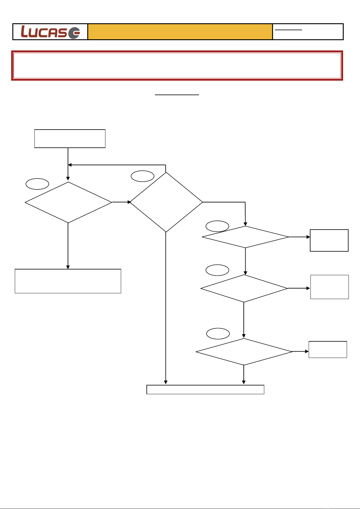
II –Malfunction of a controlled hydraulic function: the main control is faulty -4/4
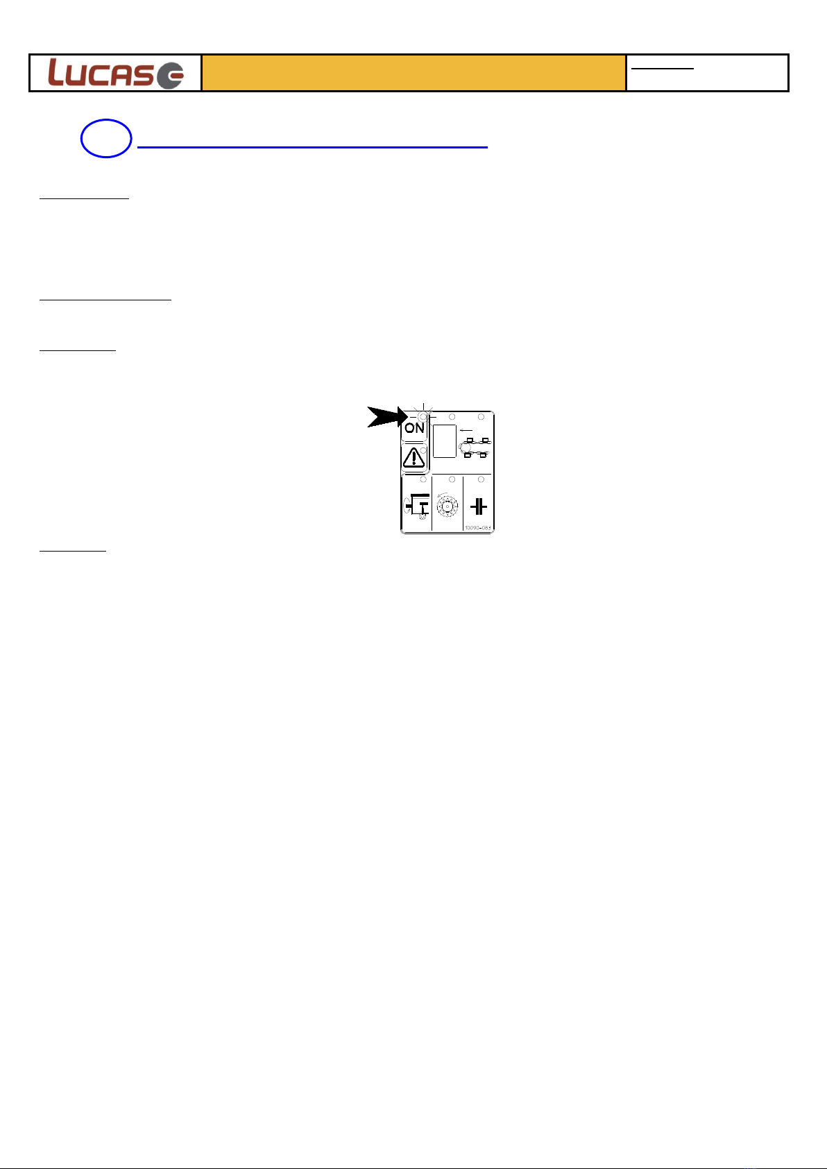
SERVICE MANUAL SHEET
Reference:
00 01 MR 87
T22 Button test
Condition:
oPlug between the machine and the telescopic handler disconnected.
oControl box switched off.
Mean of control:
oOhmmeter in continuity position.
oVisual.
Process :
oCheck the button continuity by placing the ohmmeter et the button’s terminals and pressing
it.
oCheck that the wires between the buttons and the handle’s board are not cut or unsoldered.
Result:
oIf the continuity results are bad for some buttons please replace them.
oIf some wires are cut please replace them.
oIf some wires are unsoldered please solder them again.
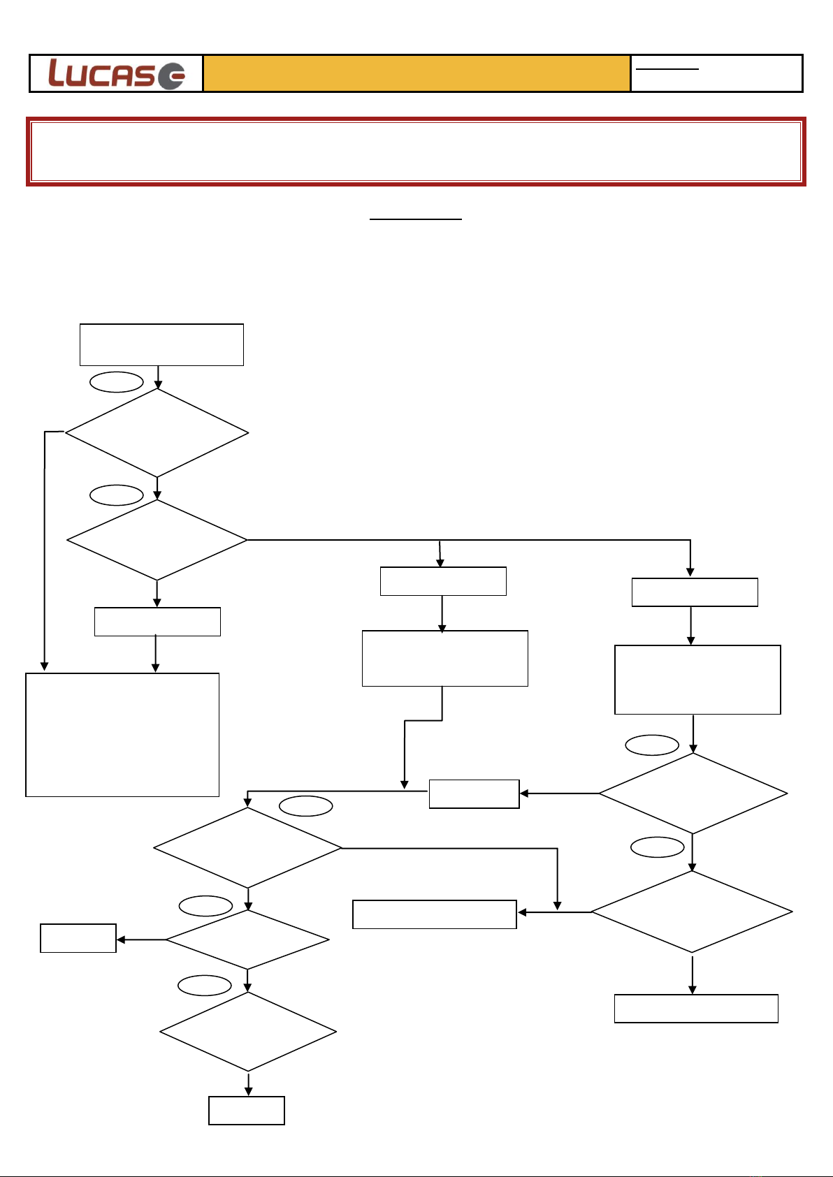
T23 Control cable test
Condition:
oPlug between the machine and the telescopic handler connected.
oControl box switched off.
oControl wires disconnected from the terminal inside the control box.
Mean of control:
oOhmmeter
Process:
oCheck the continuity for each wire of the control bundle.
oCheck the short-circuit for each wire of the control bundle.
Result:
oIf one of the cables on the telescopic handler side is faulty (between the handle and the
connecting plug of the telescopic handler), replace the whole main control.
oIf one of the cables on the machine side is faulty (between the connecting plug and the
control box), replace the handle bundle, machine side.
oIf a connecting plug is at fault, replace it.
T24 Control board test
Condition:
oDisconnect the control wires from the terminal inside the control box, and connect a handle in
working order (do this with control box switched off).
oConnecting plug between the machine and the telescopic handler connected.
oTelescopic handler in operation (in order not to be disturbed by the connections after
contact).
oControl box switched on in normal operating mode.
Mean of control:
oVisuel
process:
oInvolves checking that all the hydraulic functions are operating properly.
Result:
oIf all the hydraulic functions are ok, that means that the control’s board is faulty, replace the
main control.
oIf just one hydraulic function is at fault, the motherboard has a defect, replace it.

III –Malfunction of a hydraulic function: Fault due to the electrovalves-1/5
SERVICE MANUAL SHEET
Reference:
00 01 MR 88
III –Malfunction of a hydraulic function:
Fault due to the electrovalves
Prior checks:
Make sure that the electrical power supply is ok.
(Chap. I-General malfunction : no light comes on)
Make sure that the main control is operating properly.
(Chap. II –Malfunction of a hydraulic control: Fault due to the main control)
Make sure that the hydraulic power supply coming from the telescopic handler is ok (continuous
pumping activated, connection valves rightly mounted)
The controlled function does
not react when the
button(s) is/are pressed.
Output control
led test
T31
Bad
Good
The leds
LIGHT UP
The leds
FLASH
The Leds remain
OFF
The elctrovalves are correctly
excited.
Hydraulic problems :
- Pollution (replace the filter)
- Slide valve blocked
- Spring broken
- …
The electrovalves are not
excited.
Output circuit OPEN
Suspicion of short-circuit at
the output:
DISCONNECT all the
outputs concerned
Output control
Leds test
T32
Change the configuration
and start again the T31 test
Check program
configuration
Short-circuit at
the output
Coil test
Coil link test
Electronic problem
Replace the motherboard.
Replace the
coil
The Leds
FLASH
The Leds remain
OFF
Bad
Mauvais
Bad
Good
Good
T34
T35
Good
Test with hand
control
Bad
Good
T31
Coil and bundle
test
Bad
T30
T33
Bad
Repair the
connection

III –Malfunction of a hydraulic function: Fault due to the electrovalves-2/5
SERVICE MANUAL SHEET
Reference:
00 01 MR 88
T30 Function test with hand control
Condition:
oConnection plug between the machine and the telescopic handler connected.
oTelescopic handler in operation (in order not to be disturbed by the connections after contact).
oControl box switched on in normal operation mode.
oHydraulic power supply in continuous pumping.
Mean of control:
oVisual.
Process:
oFind out the coils corresponding to the function at fault and to the inverse one, using the table
see chap. IV –Electrovalve excitation table.
oUsing an appropriate tool, press at the end of the concerned coils.
oRepeat the previous stage for the inverse function.
Location of the electrovalves in the main block:
Location of the electrovalves in the fan block:
Résult:
oThe test is considered « ok » if the faulty function is operating in both directions. Go on with
the tests : electric or electronic problem.
oThe test is considered « bad » if the function does not operate, hydraulic problem (pollution,
slide valve blocked, spring broken, flow regulator…). If the function does not operate only in
one direction make sure it is not protected with a specific pressure limiter and check that this
limiter is not set (concerned function: loading door line A3 (130 bar) and line B3 (185 bar)).

III –Malfunction of a hydraulic function: Fault due to the electrovalves-3/5
SERVICE MANAUL SHEET
Référence :
00 01 MR 88
T31 Output control led test
The output control leds can have 3 different states:
- ON : output activated,
- FLASHING (quickly): output activated but in open circuit (ex.: electrovalve not connected),
- OFF: 2 cases, either the output is not activated, or it is, but in short-circuit (ex. Electrovalve’s
coil faulty).
Condition:
oConnection plug between the machine and the telescopic handler connected.
oTelescopic handler in operation (in order not to be disturbed by the connections after contact).
oControl box switched on in normal operation mode.
oControl box open.
Mean of control:
oVisual.
Process::
oFind out the outputs corresponding to the function at fault using the table, see chap. IV –
Electrovalve excitation table.
oSwitch off the control box, then switch it on again (this ACTION is VITAL, as each time it is
put into service the box performs an output status self test (normal, open, or short circuited).
oActivate the faulty function and check the state of the output control Leds in question.
Résult:
oThe concerned control Leds are ON, no electronic problem, but hydraulic problem.
oThe concerned output Leds are FLASHING, the circuit is open, go on with the tests.
oThe concerned control leds are OFF, the circuit may be short-circuited, go on with the tests.

III –Malfunction of a hydraulic function: Fault due to the electrovalves-4/5
SERVICE MANUAL SHEET
Reference:
00 01 MR 88
T32 Check the program configuration
See chap. V –Check the program configuration.
T33 Coil and cable unit test
Condition:
oConnection plug between the machine and the telescopic handler connected.
oTelescopic handler in operation (in order not to be disturbed by the connections after contact).
oControl box switched off.
Mean of control:
oVisual.
Process:
oFind out the outputs corresponding to the function at fault using the table, see chap. IV –
Electrovalve excitation table.
oChange the faulty coil and cable unit with a running coil and cable unit already mounted onto
the valve assembly (replace with the box switched off).
oSwitch on the control box and operate the faulty function to check that everything is operating
correctly.
Please note : If this inversion operation between both coil and cable units is not possible (no identical
coil on the valve assembly, several faulty functions,…), please follow the next stage.
Result:
oChanging the coil and cable unit enabled to solve the problem; continue the tests to find out
the faulty component (coil or cable).
oThe operation has not solved the problem. The problem is electronic: replace the motherboard.
T34 Coild test
Condition:
oConnection plug between the machine and the telescopic handler connected.
oControl box switched off.
oCoil disconnected.
Mean of control:
oOhmmeter.
Process:
oControl the coil resistance, as mentioned here after.
Résult:
Result
Observation
Action
R < 2 ohms
The coil is short-circuited,
coil out of order.
Replace the coil.
R > 6 ohms
The coil is cut, coil out of order.
2 ohms < R < 6 ohms
Coil ok.
Test ok, continue the tests.

III –Malfunction of a hydraulic function: Fault due to the electrovalves-5/5
SERVICE MANUAL SHEET
Référence :
00 01 MR 88
T35 Coil connection test
Condition:
oConnection plug between the machine and the telescopic handler connected.
oControl box switched off.
oCable to be controlled disconnected at both ends (terminal + connections).
Mean of control:
oOhmmeter.
Process:
oControl the continuity for each bundle wire.
oControl the short-circuit for each bundle wire.
Result:
oIf one of the controls turns to be faulty replace the bundle.

IV –Electrovalve excitation table - 1/1
SERVICE MANUAL SHEET
Reference:
00 01 MR 89
IV –Electrovalve excitation table
MACHINE description Telescopic Raptor
C
Standard
PROG configuration 010
MODULE
BUTTON
PRESS
FUNCTION
ELECTROVALVES
EXCITED
M
Module FAN rotation S13
CONVEYOR FLOOR and BEATER-BAR : standard progress S1 - S3 - S11
(1) CONVEYOR FLOOR and BEATER-BAR: forced FORWARD operation S1 - S3 - S11
(2) CONVEYOR FLOOR and BEATER-BAR: forced REAR operation S2 - S4 - S11
(S + 1) REAR door: opening S5 - S11
(S + 2) REAR door: closing S6 - S11
(3) CAP: opening S9 - S12
(4) CAP: closing S10 - S12
(S + 3) CHUTE rotation to the LEFT hand side of the machine S7 - S12
(S + 4) CHUTE rotation to the RIGHT hand side of the machine S8 - S12
Program : CE010-151 v…….
Original PROG configuration : 000
Level of equipment
LOADING / DISTRIBUTION
1 + 21 + 2
3 + 4

V –Setting program configuration -1/1
SERVICE MANUAL SHEET
Reference:
00 01 MR 58
V –Setting program configuration
The "CONFORT" control box is a multipurpose piece of equipment which is fitted to many LUCAS.G machines. It
has internal settings so that it can be configured to the machine in question and its level of equipment.
This configuration is factory set but can be changed then for the following reasons:
- The motherboard must be changed after a breakdown,
- The machine’s level of equipment has changed (coupling, second control station).
To configure this board you just need to do a single setting characterized by a 3-digit number. To find out the
program configuration according to the machine’s level of equipment, please read the chapter IV –Electrovalve
Excitation Table.
This configuration must be set in the electronics via the control handle and control box.
Condition:
oTractor’s power plug connected.
oTractor is running (in order not to be disturbed by the « COBO » connections after contact)
oControl box switched off.
Procedure:
Phase
User action
Control box status
Comments
1
START-UP
Indicator light ON (green).
2
Open the control box.
3
On the right hand-side of the
display press once on the S1
button (control box open)
This allows you to switch to
configuration setting mode.
The active program number
is displayed (by default 000
= no program)
4
Press buttons or to
change the digit displayed
and get the value required.
Long press on buttons or
enables to have the digits
displayed continuously.
Values are endlessly
repeated.
5
Close the control box
6
VALIDATION of PROG value.
Return to normal working
mode.
Program number
S1

VI –Alarm indicators -1/1
SERVICE MANUAL SHEET
Reference:
00 01 MR 61
VI –Alarm indicators
Alarm indicator on
STEADY
Alarm indicator on
steady only for a
specific function
(1)
The lighting up of the alarm
indicator corresponds to a
defective function
Yes
Continue to chap. III –Malfunction of a
controlled hydraulic function:
Fault due to electrovalves
Alarm indicator on steady
all the time
Electronic problem
Change MOTHERboard
No
Alarm indicator
FLASHING
Power supply tension in
terminal in control box
between 9V and
15V.
Repair tractor electrical
power supply
No
Electronic problem
Change MOTHERboard
Yes
(1) Switch off the box and switch it
back on again to check this
condition.

VIII –Malfunction of the base conveyor safety device (+clutch) -1/5
SERVICE MANUAL SHEET
Reference:
00 01 MR 90
VIII –Malfunction of the base conveyor safety device
Prior checks:
Make sure that the fan is operating correctly.
Make sure that the hydraulic power supply coming from the telescopic handler is correct
(continuous pumping activated, connection valves rightly activated).
Make sure that the hydraulic part is operating correctly (Chap. III –Malfunction of a
hydraulic function: electrovalves are faulty)
Check that the 3 detector’s wires are properly connected to the motherboard.
The « BASE CONVEYOR »
safety device is activated
untimely at each start-up:
The display flashes « E ».
Proximity
detector
test
Detector/
collar
distance test
T81
Bad
Good
Bad
Board input
test
Good
Electronic problem
Change the motherboard
T80
T82
Setting
Mauvais

VIII –Malfunction of the base conveyor safety device (+clutch) -2/5
SERVICE MANUAL SHEET
Reference:
00 01 MR 90
T81Proximity detector test
Condition:
oConnection plug between the telescopic handler and the machine connected.
oThe telescopic handler is running (in order not to be disturbed by the connections after
contact).
oMachine’s hydraulic plugs are disconnected from the telescopic handler.
oControl box switched ON in normal operation.
Mean of control:
oVisual.
Procedure:
oUnscrew both screws and remove the detector to have access to the fan’s detector pinion.
oPut a filled part of the fan’s detector pinion in front of the detector’s passage hole.
oCheck that the led located on the proximity detector on the left-hand side of the fan’s
hydraulic motor, on the front side of the machine:
- Is ON when a filled part of the pinion is in front of it,
- Is OFF when a pinion cutting is in front of it.
Résult:
oIf the detector’s led is not ON when opposite to a filled part of the pinion, the test result is
“bad”. Go on with the tests and control the detector/pinion distance.
oIf the detector’s led is ON when opposite to a filled part of the pinion, the test result is
« good ». Continue with the tests.
Filled part
Cutting
Detector’s passage
hole
Fan’s detector
pinion

VIII –Malfunction of the base conveyor safety device (+clutch) -3/5
SERVICE MANUAL SHEET
Reference:
00 01 MR 90
T81 Detector/ pinion distance test
Condition:
oConnection plug between the telescopic handler and the machine disconnected.
oTelescopic handler is stopped.
oControl box is OFF.
Mean of control:
oVisual
oWedge
Procedure:
oInvolves checking that the distance between the end of the detector and the filled part of
the fan’s detector pinion is comprised between 2 and 2,5 mm.
Result:
oIf the test result is « bad » do the setting to get the requested distance.
oIf the test result is « ok », continue with the tests.
Fan’s detector
pinion

VIII –Malfunction of the base conveyor safety device (+clutch) -4/5
SERVICE MANUAL SHEET
Reference :
00 01 MR 90
T82Board input test
Condition:
oConnection plug between the telescopic handler and the machine connected.
oThe telescopic handler is running (in order not to be disturbed by the connections after
contact).
oControl box switched ON in normal operation mode.
oControl box open.
oProximity detector connected.
Mean of control :
oVisual.
Procedure:
oCheck that the detector power supply control led is ON « +H ».
oCheck that « H » detector input control led lights up when a bridge is established between
the “Masse” and the “H” point of the terminal and goes off when it is opened.
Comment : The sensor input leds are lit weakly all the time : this state is considered to be « off ».
Result:
oIf one of the previous test is « bad » replace the motherboard.
oIf the test result is « ok » replace the proximity detector.

VIII –Malfunction of the base conveyor safety device (+clutch) -5/5
SERVICE MANUAL SHEET
Reference:
00 01 MR 90
oOperating procedure without safety device
This operating mode must only be used temporarily as the safety device is
deactivated. In this case there is a serious risk that some components may be damaged
definitively, what then cannot be covered by the manufacturer guarantee.
Condition:
oConnection plug between the telescopic handler and the machine connected.
oThe telescopic handler is running (in order not to be disturbed by the connections after
contact).
oControl box switched on in distribution operation mode.
Stage
User’s action
State of the control box
Comments
Confort
Intuitive
1
Operation of the base
conveyor to activate
the safety device.
"SAFETY DEVICE
ACTIVATED »
Quick press
2
Open the control box
3
Disconnect the proximity
detector (H, +H, masse
points)
Quick press on the S1 button
inside the control box.
Set to
"SAFETY DEVICE
DEACTIVATED"mode
(operational action
only when the safety
device is activated,
« E » flashing)
4
Close the control box.
5
Return to the
distribution mode.
6
The control leds for the base conveyor,
beater-bar rotation and clutch flash to
indicate the operating mode without
safety device.
All the functions of the
distribution mode can
be used normally. Only
the safety device is
deactivated.
Comment: The operating mode without safety device remains active as long as there is still a problem
on the rotation detector. However, as soon as the rotation detector is active again, the operating
mode without safety device is AUTOMATICALLY CANCELLED and replaced with the normal operating
mode with safety device active.
Table of contents
Other LUCAS Farm Equipment manuals
Popular Farm Equipment manuals by other brands

Brinsea
Brinsea ChickSafe Advance Installation and operating instructions

Hardi
Hardi COMMANDER TWIN FORCE Instruction book

horsch
horsch SW 3500 S operating instructions

SIP
SIP STAR 300 Instruction for work

Westfield
Westfield GULP2 HOPPER MKX130 Assembly & operation

Del Morino
Del Morino Rotex 90 Manual of use and maintenance