LUCAS CASTOR 30 R User manual

Ref. : D370-004_4
INSTRUCTION MANUAL –MASTER VERSION
INSTRUCTION MANUAL
PLEASE READ CAREFULLY BEFORE USING THE MACHINE.

- 1 - D370-004_4
PREFACE
This machine is a semi mounted machine designed for feeding herds.
It provides :
For all models: forage transport and straw bedding.
For CASTOR + exclusively: The distribution of fodder.
For C-KATOR exclusively: The chopping of the STRAW.
This instructions manual provides all information required for correct operation of the
machine, as well as adjustment and maintenance procedures.
Some of the illustrations in this user's manual may have been made on the basis of
prototype machinery. The standard production models may differ with respect to certain
details..
TO OBTAIN TOP PERFORMANCE FROM YOUR MACHINE PLEASE READ CAREFULLY ALL
INSTRUCTIONS PROVIDED.
KEEP THESE INSTRUCTIONS TO HAND FOR LATER CONSULTATION AND PASS THEM ON
TO ANY OTHER USER, INCLUDING UPON SELLING THE MACHINE.
Information level :
WARNING
Information relative to your safety.
IMPORTANT
Information concerning the risk of damaging your machine.
NOTE
Further information.

- 2 - D370-004_4
SAFETY RULES
1. The other chapters of the instruction leaflet contain further indications that you must also follow for your
own safety.
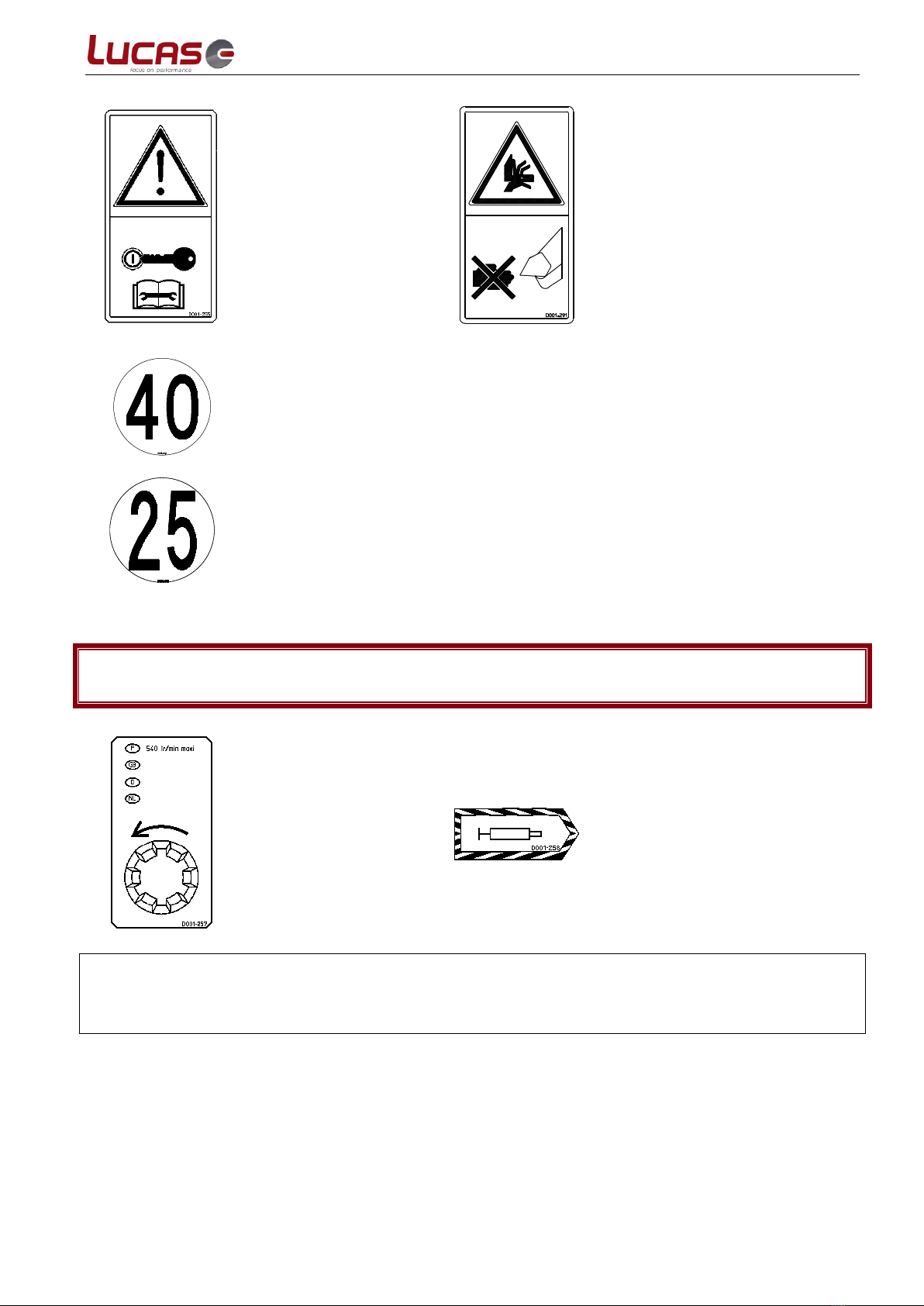
2. Comply at all times with the safety rules as set out in the pictograms glued onto the machine for that
purpose.
3. Remember that the watchwords for your safety are caution and vigilance.
4. Proper maintenance will ensure maximum safety, correct operation and a longer life for your machine.
5. Keep the safety devices in position at all times.
6. Do not wear loose clothing, long hair hanging free or jewellery liable to get caught or jammed in the
moving parts of the machine.
7. Rules and regulations relating to accident prevention and safety, industrial medicine, environmental
protection and road traffic must be followed at all times.
8. Whenever the machine is being moved, the hand brake lever must be connected to the tractor. When
driving on public roads, observe the highway code and particularly with the 25 kph or 40 kph speed limit
according homologation.
9. The machine must be controlled by a single person who has been trained to use it. In the event of use by
a trainee or a temporary outside worker, the owner must advise and train the user in the rules of safety
and correct use.
10. Ensure that the area around the machine is clear of people, animals and obstructions when starting up
and during operations.
For the C-KATOR, due to the high inertia of the fan. Make sure there are nobody within 20m around the
machine in operation - Risk of injury from thrown objects with bouncing.
11. It is strictly forbidden to use the machine for transporting people, animals, or objects of any kind.
12. Never attempt to remove matter from the machine until it and the tractor have both come to a complete
stop (this recommendation is highly important for jobs using the distribution outlet where there is a risk
of mutilating a finger or hand on the support plate or on the sections of the beater-bar). Whatever the
type of intervention to be carried out (greasing, adjusting, maintenance, ...), first stop the tractor
engine. Disconnect all energy sources (transmission shafts, hydraulic and electrical take-off).
13. Whenever you hear a sound or feel a vibration out of the ordinary, stop the machine, find and remove
the cause of the trouble before resuming work. If necessary, call your dealer.
14. Before doing any work on the machine, first ensure that it cannot be started up accidentally.
15. Before operating the machine, check that all screws, bolts and connectors are tight. Tighten where
necessary.
Before using the C-KATOR, check in particular the condition and tightness of the knives mounted on the
rotor.
16. Before operating the machine, after any adjustment or maintenance operation, check that all protective
devices are in place and in an adequate state of repair, and that they are properly locked.
17. Do not step on any part of the machine other than areas designed for the purpose (ladder).
18. All remote controls (cable, hose, etc) must be positioned in their intended places so as to prevent them
from accidentally triggering some manoeuvre liable to cause an accident or other damage.
19. In case the machine is equipped with a magnetic extraction the persons wearing a cardiac simulator
must stand at least 2 m far from the distribution chute.
20. Under no circumstances may the rear gate on the machine be used as a lifting device.
NOTE : All references to "right" and to "left" in this booklet concern the corresponding direction as seen
from the rear of the machine looking towards the front.

- 3 - D370-004_4
IDENTIFICATION OF THE MACHINE
This machine is identified by a "MAKER'S" plate located on the right-hand side of the
machine.
You can note down your machine characteristics below.
Kits are identified too by a “MAKER’s” plate
located on the kit edge.
DO NOT REMOVE THE PLATES MOUNTED ON YOUR MACHINE.
WHAT TO DO IN THE EVENT OF A BREAKDOWN
In the event of a failure or breakdown with your machine, you should contact your
dealer : LUCAS.G
To avoid any confusion when ordering spare parts you will be asked to give the serial
number of your machine.
NOTE : Spare parts that have been disassembled will not be covered by the
warranty.

- 4 - D370-004_4
CONTENTS
PREFACE......................................................................................................................... 1
SAFETY RULES ................................................................................................................ 2
IDENTIFICATION OF THE MACHINE................................................................................ 3
WHAT TO DO IN THE EVENT OF A BREAKDOWN.............................................................. 3
CONTENTS ...................................................................................................................... 4
DESCRIPTION OF THE SAFETY PICTOGRAMS.................................................................. 5
DESCRIPTION OF THE OPERATION PICTOGRAMS ........................................................... 6
TECHNICAL CHARACTERISTICS ...................................................................................... 7
TECHNICAL CHARACTERISTICS KIT................................................................................ 9
1 - START-UP................................................................................................................ 10
1.1. HANDLING AND STORAGE ............................................................................................. 10
1.2. TRACTOR FITTINGS ..................................................................................................... 10
1.3. COUPLING ............................................................................................................... 11
1.4. CHECKING HYDRAULIC FUNCTIONS.......................................................................... 13
1.5. CHECKING ROTATING PARTS .......................................................................................... 32
2 - OPERATION............................................................................................................. 33
2.1. LOADING................................................................................................................. 33
2.2. TRANSPORTING ......................................................................................................... 35
2.3. DISTRIBUTION .......................................................................................................... 36
2.4. STRAW SPREADING..................................................................................................... 42
2.5. CHOPPING (ON C-KATOR). ........................................................................................... 43
2.6. WEIGHING............................................................................................................... 44
2.7. OPERATING FAILURES AND REMEDIES................................................................................ 44
3 - MAINTENANCE ........................................................................................................ 48
3.1. MAINTENANCE POINTS ................................................................................................. 48
3.2. LUBRIFICATION PLAN................................................................................................... 50
3.3. MAINTENANCE METHODS .............................................................................................. 51
3.4. REMOVAL AND STORAGE ............................................................................................... 58
3.5. DISMANTLING AND DISPOSAL......................................................................................... 58

- 5 - D370-004_4
DESCRIPTION OF THE SAFETY PICTOGRAMS
Risk of crushing the chest
or lower limbs.
Keep away from the
articulation zone for as
long as the engine is
running.
Caution : rotating parts.
Before carrying out any
maintenance please wait a
minute and a half until the
rotating elements are
completely stopped, which is
indicated either by the clicking
sound of the transmission free
wheel or by the gearbox handle
rotation.
Risk of objects being
discharged or projected.
Keep at a safe distance
from the projection area
while the machine is
running.
Read the user manual.
It is absolutely forbidden
to climb into the machine
body at any time when
the power take off is
connected to the tractor
and the engine is
running.
Danger of chopping off fingers
or the whole hand between the
fan blades and the back plate or
the sections of the beater-bar.
Use some implement when
clearing jammed material.
During operation, no one
must stand close to the
machine
Risk of the fingers or the whole
hand getting caught.
Do not open or remove the
protective casings whilst the
engine is running.
Caution :
Risk of injury
Anchor point

- 6 - D370-004_4
Stop the engine and
remove the key before
carrying out any
maintenance work.
Risk of crushing the fingers or
the whole hand.
Never move your hand towards
running mechanisms.
or
Maximum authorised
speed in Kph
DESCRIPTION OF THE OPERATION PICTOGRAMS
Maximum permitted
rotation frequency at
the machine input.
Grease according to frequencies
indicated in the maintenance
paragraph in the user manual.
Keep warning notices and pictograms clean and visible at all times. Ask your dealer for fresh
stickers if they become damaged. The part number is indicated on the bottom right side of the
sticker.
When making repairs, ensure that spare parts carry the same stickers as the original parts.

- 7 - D370-004_4
TECHNICAL CHARACTERISTICS
Castor+ 30/
C-Kator 32
Castor+ 60
Recommended power (CV) :
65 / 100
65
Frame interior dimensions
W x H x L (m)
1,45 x 1,4 x 1,2
3,08 x 1,4 x 1,2
Loading capacity (m3)
2,75
2,75
Empty weight (kg) / Usual load (kg)
from 1900 to
2700 kg
according to the
equipment (see
the plate)
from 2700 to
3500 kg
according to the
equipment (see
the plate)
Toothed beater-bar
1
1
Side for distribution
Right
Right
Straw spreading side R
Right
Right
RU
270° spreading
area
270° spreading
area
Drive
Power take off
540 rpm.
Power take off
540 rpm.
Coupling Standard
Double pivot
Double pivot
Optional
Piton or screed
Piton or screed
Road lighting
Yes
Yes
2 fan rotation speeds
Distribution
Distribution
at 540 rpm Pto
Straw spreading
Straw spreading
Breaking system
None
None
Standard tyre fitting
10.0/75–15.3 14PR
11.5/80–15.3 14PR
Noise Db(A)
77
77
Maximum authorised speed (kph)
40
40
A
3 773 mm
5 411 mm
B
5 359 mm
6 997 mm
C
4 685 mm
6 323 mm
D
6 270 mm
7 908 mm

- 8 - D370-004_4
CASTOR+
80R
CASTOR+
80RU
Recommended power (CV) :
65
65
Frame interior dimensions
W x H x L (m)
3,65 x 1,4 x 1,33
3,65 x 1,4 x 1,33
Loading capacity (m3)
6,70
6,70
Empty weight (kg)
3 040
3 150
Usual load (kg)
4 400
4 400
Toothed beater-bar
2
2
Side for distribution
Right
Right
Straw spreading side
Right
270° spreading
area
Drive
Power take off
540 rpm.
Power take off
540 rpm.
Coupling : Standard
Double pivot
Double pivot
Optional
Piton or screed
Piton or screed
Road lighting
Yes
Yes
2 fan rotation speeds
at 540 rpm Pto
Yes
Yes
Hydraulic braking
Yes
Yes
Standard tyre fitting
11.5/80 –15.3
11.5/80 –15.3
Noise Db(A)
77
77
Maximum authorised speed (kph)
25
25

- 9 - D370-004_4
TECHNICAL CHARACTERISTICS KIT
Comb cylinder kit
This kit is composed of :
A –A deviator unit and its cables
B –Two comb mounting guide flanges and its fixings
C –A hydraulic comb.
Weight: 21 kg
Magnetic extraction kit
Weight : 50 kg
Fixed coupling kit : Weight 110 kg
Collecting gate kit : 1200kg
Hopper 500l
HOPPER KIT (500 l)
Frame interior dimensions (m)
Loading capacity (litres)
Empty weight (kg)
1,79 x 0,53 x 0,59
500
190
A
B
C
D
2000
542
784
1787
Consult the instructions supplied with the hopper.

- 10 - D370-004_4
1 - START-UP
1.1. HANDLING AND STORAGE
The machine must be stored taking a minimum of precautions :
-Machine on the ground, stable
-Ensure stems on all actuators are greased when kept in storage. Prior to operation,
these same rods should be cleaned with a cloth moistened with diesel fuel and then
dried with a clean, dry cloth.
-Once uncoupled, the transmission must not be laid on the ground, but must rest on the
mounting provided for the purpose.
-The parking brake on. (if this)
-The handling of the Castor 30R (only) is possible by lifting slings. Use the attachment
points provided for this purpose and spotted on pictograms.
1.2. TRACTOR FITTINGS
Hydraulic fittings
* Hydraulic source :
. A single-acting hydraulic distributor (+ return) or a double-acting one (two female ½ clack
valves).
. Distributor maintained in continuous pumping.
. Direct return to the tank recommended so as to reduce oil heating.
. For self-regulating pumps, compulsory return to the bowl.
* Nominal flow rate : 15 - 80 l / min. (optimum flow rate : 40 –60 l / min.)
* Maximum available pressure : betwen 160 and 200 bars.
* Circuit tape :
. The machines are factory set for open centre hydraulics.
* Closed centre hydraulics adaptation :
. For CONFORT control machines : see chapter 1.4.1.5
. For INTUITIVE control machines: see chapter 1.4.2.5
IMPORTANT
It is forbidden to operate the tractor with a delivery rate of over 70 l/min. On tractors with a
higher delivery rate, this must be reduced so as to obtain an optimum perating rate of between
35 and 50 l/min. (Beyond this delivery rate, there is a risk of verheating and damage to the
hydraulic circuit not covered by the warranty).
WARNING
In order for the controls to work in the right direction, make sure never to connect the
hoses blue and red mark on the tractor the wrong way around.
OIL POLLUTION IS NOT COVERED BY THE WARRANTY, KEEP THE VALVES CLEAN
ELECTRIC FITTINGS
Standard 12V 7 contact
connector (European code)
POWER TAKE-OFF
6 straight 1"3/8
splines
540 rpm
EYE BOLT COUPLING
with safety pin or fork
joint coupling
ELECTRICAL CONNECTION
3 pin 12 volt DIN 9680 for
power supply
CAUTION : required
intensity 25 A (only for
machine control or INTUITIVE
COMFORT)
2-POINT COUPLING
class 2
(Stabilizers blocked for good
overall tractor and machine
stability)
HYDRAULIC BRAKE
CONNECTOR

- 11 - D370-004_4
1.3. COUPLING
1.3.1. Articulated coupling
Position the drawbar on the tractor arms, holding it in place with the pins.
Set and block the stabilizers so as to obtain good overall tractor and machine stability.
Couple the machine to the tractor placing the drawbar sleeve to face the coupling pin.
Install the retaining ring, insert the pin and pin.
1.3.2. Fixed coupling gear
Position the machine horizontally on level ground or on a level in relation to the ground.
Ensure that the coupling ring is at the same height as the tractor coupling.
If this is not the case, make the necessary adjustment with the holed plates connecting
to the coupling jib by turning the jib a hole.
Ring support
Coupling bar
Emergency chain
Tractors' arm
Stop ring
Pin
Pin

- 12 - D370-004_4
Make the various connection
.Hydraulic
.Electrical
.Mechanical
.Transmission
.Chain back to cable brake lever,
.Undo the brake if this park.
WARNING
Take precautions to avoid getting trapped between the tractor and the machine. When
using the machine during travel, no one will be found placed between the tractor and
the machine.
1.3.3. Uncoupling
Set the machine on the ground in the manner indicated in the "handling and storage"
section.
Apply the tractor brakes.
Switch off the tractor engine.
Apply the machine parking brake.
Disconnect the various connection::
.Hydraulic
.Electrical
.Mechanical
.Transmission
.Brake cable or emergency chain
WARNING
Check that both the tractor and the machine brakes are really on.
With articulated coupling :
. Disconnect the bar
or
. Unpin, remove the pin, ring and ask about the support provided for this purpose.
With fixed coupling :
. Lower the leg and lift the drawbar by manipulating the stand.
. Remove the pin or peg clevis.
Move the tractor.
1.3.4. Checking the transmission shaft
Follow instructions contained in the maker's transmission instructions manual delivered
with your machine.
WARNING
To avoid any damage the turning circle tractor/machine must always been less than the angle the
shaft drive transmission does accept (80° in standard and 60° in wide angle option).
WARNING
To avoid damage to the transmission shaft, do no raise the lifting mechanism too high.

- 13 - D370-004_4
1.4. CHECKING HYDRAULIC FUNCTIONS
WARNING
Prior to operation, even unloaded, always check that there are no foreign bodies still
remaining in the body. Likewise, there must be no one standing close by either during
inspection or operation
1.4.1. "CONFORT" control machines
1.4.1.1. Tractor fitting : handle mounting
To get the best out of the control handle, it needs to be mounted in the cab Two handle
mountings are provided for the purpose behind the machine's front right-hand casing for
fitting onto the tractor(s) cab. This mounting must be fitted onto the right-hand bracket
of the tractor (by your approved dealer when commissioning the machine), to be
disposed as follows :
. To have the handle positioned in such a way as to ensure maximum operator
comfort when operating the machine from the tractor seat .
. Not to hamper the other tractor controls.
Control handle to be mounted and removed
at each coupling –uncoupling
Mounting fixed onto the tractor(s) cab
Also supplied for two tractors are two stickers to be placed on the windows, providing all
information necessary for operating the "CONFORT" control.
1.4.1.2. Components of the "CONFORT" control
a) Control handle
This handle is located in the cab, mounted on the purpose-designed bracket.
This handle has six buttons (M –S –1 –2 –3 –4) as set out below, to control all the machine
units.
Button (S) located on the
back of the handle
Buttons (M –S –1 –2 –3 –4)
located on the front

- 14 - D370-004_4
b) Display box
1. Overview
This box displays all the controls. It is made up of windows as indicated below.
Functional module windows
"CONTROL" window
Load
module
Distribution
module
2nd station
module
(*)
"ON / OFF" window
"ALARM" window
(*) Only for machines equipped kit second control station
2. Control box
Base conveyor control pilot lights
Pilot lights off : base conveyor stationary
Pilot lights on : base conveyor in operation
Display : base conveyor control
* Display off : no base conveyor
* "Fixed" display on with an indication from 0 to
9 : indicates base conveyor (pre-selected or
actual) speed
. 0 : zero speed
. sequenced intermediate speeds
. 9 : continuous maximum speed
* Display on indicating "9" with rapid flashing :
indicates base conveyor in forced forward
operation
* Display on indicating "A" with rapid flashing :
indicates base conveyor in forced reverse
operation
* Display on indicating "E" with rapid flashing :
indicates base conveyor is blocked in "safety"
Hopper auger
control or sprayer
pilot light
(for the machines
fitted with only)
Beater-bar rotation
control pilot light
Pilot light off : beater-bars
stopped (or turning at very
low speed)
Pilot light on : beater-bars
turning
Beater-bar clutch control pilot light
(for the machines fitted with only)
Pilot light off : beater-bars disengaged
Pilot light on : beater-bars engaged

- 15 - D370-004_4
1.4.1.3. Operating the Confort control
WARNING
Prior to operation, even unloaded, always check that there are no foreign bodies still
remaining in the body. Likewise, there must be no one standing close by either during
inspection or operation
Pressurise the hydraulics (continuous pumping) (tractor idling).
a) Key
PRESS BUTTONS
PILOT LIGHT AND DISPLAY STATUS
Press button M :
The function remains
enabled on releasing
the button
Pilot lights Display
Off
Flashing
Steady on
Press button M :
The function stopped
on releasing the
button
b) Starp-up –Module change - Stop
USER INSTRUCTINS
CONTROL BOX STATUS
FUNCTION USED
START-UP
Lamp ON (green)
lighted up
(no function
available)
Activation
Starp-up –
Module change
- Stop

- 16 - D370-004_4
USER INSTRUCTINS
CONTROL BOX STATUS
FUNCTION USED
Activation
DISTRIBUTION
MODULE
Activation
2ND STATION
MODULE
(for the machines
fitted with only)
Otherwise direct
change over to the
following module
Activation
Starp-up –
Module change
- Stop
(Looping)
Etc, etc… (continuous looping of modules)
Hold down the button
for 3s
STOP OF THE
CONTROL SYSTEM
Moreover, the system
is equipped with a
"AUTO-OFF" which
disconnects the
system after 60
minutes of non-
activity.

- 17 - D370-004_4
c) LOADING MODULE
CONTROL BOX STATUS
BUTTON POSITIONS ON HANDLE
Extract from the in-cab control sticker
Arm –claw –axle control
Fittings not installed
Base conveyor control(*)
Simultaneously short press (S+ 1) : forced
forward operation
Simultaneously short press (S+ 2) : forced
reverse operation
Tailgate control
Simultaneously short press (S+ 3) : To close
Simultaneously short press (S+ 4) : To open
(*) For “twin” machines : for this base conveyor control both conveyors are
systematically activated at the same time, whatever the preselection in the distribution
module can be.

- 18 - D370-004_4
d) Distribution Module : base conveyor control
CONTROL BOX STATUS
BUTTON POSITIONS ON HANDLE
Double conveyor control
Rear base conveyor
preselection control.
Quick simultaneous press S +
1 + 2
Base conveyor speed adjustment
Press (by pulse) on : base conveyor acceleration
the displayed figure is incremented with each pulse
Press (by pulse) on : base conveyor deceleration
Extract from
the in-cab
control sticker
Standard base conveyor control + clutch
(*)
Quick simultaneous press 1 + 2 : Clutch start (*)
(1 sec time delay) + Starting up the base conveyor
Quick simultaneous press 1 + 2 : stop base conveyor
(1 sec time delay) + Disengage clutch (*)
Or Quick press M :
Emergency stop base conveyor
+ clutch simultaneously (*)
+ simultaneous hopper auger shutdown (**)
Base conveyor forced operation
Prolonged press (1) : forced forward
operation
Prolonged press (2) : forced reverse
operation
* Forced operation is enabled after a one-
second time-delay.
** On releasing these forced controls, you
return to the base conveyor operating
mode prior to pressing the button.
(*) For machines fitted with the electrical clutch of the beater-bars only.
This electrical clutch is used for starting and stopping the beater-bars independently of the fan
whilst ensuring the limit of the torque transmitted to the beater-bars.
Important remark :
Since the clutch requires a running-in period, it is normal that it is noisy (“squeak” at start)
during the first weeks you use it.
(**) For machines fitted with the hopper kit only.
Deactivation
Activation

- 19 - D370-004_4
e) Distribution Module : Other functions
CONTROL BOX STATUS
BUTTON POSITIONS ON HANDLE
Extract from the in-cab control sticker
Hopper door control
(for the machines fitted with only)
Hat control
Press (3) : To open
Press (4) : To close
Mixing net control
Fittings not installed
Chute rotation control
Simultaneously short press (S+3)
: Rotation towards machine left-
hand side.
Simultaneously short press (S+4)
: Rotation towards machine right-
hand side.
Adjustable comb control
Simultaneously short press (1+3) :
Reverse
Simultaneously short press (2+4) :
Forward
This manual suits for next models
4
Table of contents
Other LUCAS Farm Equipment manuals
Popular Farm Equipment manuals by other brands

Brinsea
Brinsea ChickSafe Advance Installation and operating instructions

Hardi
Hardi COMMANDER TWIN FORCE Instruction book

horsch
horsch SW 3500 S operating instructions

SIP
SIP STAR 300 Instruction for work

Westfield
Westfield GULP2 HOPPER MKX130 Assembly & operation

Del Morino
Del Morino Rotex 90 Manual of use and maintenance