Lucent Technologies Galaxy Power System 2408 User manual

Product Manual
J85500E-4
Select Code 167-792-158
Comcode 108135021
Issue 2
September 1998
Lucent Technologies
Galaxy Power System 2408
(GPS 2408)
Notice:
Every effort was made to ensure that the information in this
document was complete and accurate at the time of printing.
However, information is subject to change.
© 1997 Lucent Technologies
All Rights Reserved
Printed in U.S.A.

Lucent Technologies Galaxy Power System 2408
Issue 2 September 1998 Table of Contents - 1
Table of Contents
1Introduction
General 1 - 1
Architecture 1 - 1
Applications 1 - 2
Customer Training 1 - 2
Customer Service 1 - 2
Technical Support 1 - 2
Product Repair and Return 1 - 3
Warranty Service 1 - 3
2Product Description
Galaxy Power System Overview 2 - 1
Plant Configuration 2 - 3
Plant Specifications 2 - 5
Galaxy Rectifier Controller 2 - 6
Circuit Boards 2 - 7
596B3 Rectifier 2 - 10
Features 2 - 11
Rectifier Specifications 2 - 13
596B3 Rectifier Control and Monitoring 2 - 15
596B3 Rectifier Status Messages 2 - 16
Rectifier Shelf 2 - 16
ES682H Converter 2 - 16
Converter Shelf 2 - 16
Features 2 - 17
Converter Specifications 2 - 19
AC Input Panel 2 - 19
24-volt DC Distribution Panel 2 - 20
48-volt DC Distribution Panel 2 - 20
Battery Connection Panel 2 - 20
Low Voltage Battery Disconnect 2 - 21
3Ordering Information
Standard Configurations 3 - 1
Custom Configurations 3 - 3

Lucent Technologies Galaxy Power System 2408
2 - Table of Contents Issue 2 September 1998
Field Mounted Equipment 3 - 3
Field Mounted Equipment 3 - 10
Spare Parts 3 - 13
Documentation 3 - 14
4Sa
f
et
y
Safety Statements 4 - 1
Warning Statements And Safety Symbols 4 - 3
Precautions 4 - 4
5Installation
General 5 - 1
Installation Tools and Hardware 5 - 1
Unpacking and Handling 5 - 2
Frame Installation 5 - 4
Cable Routing Strategy 5 - 4
Frame Ground 5 - 5
Central Office Ground 5 - 5
Getting Started 5 - 5
Connecting AC 5 - 7
Connecting Loads 5 - 11
Installing Rectifiers and Converters 5 - 11
Removing Rectifiers and Converters 5 - 11
Turning Up the Plant 5 - 12
Setting Rectifier Slot ID 5 - 13
Lamp Test 5 - 13
Installing Batteries 5 - 14
Setting the Plant Configuration 5 - 14
Voltage Calibration 5 - 15
Testing Plant Thresholds 5 - 16
Testing Rectifiers and Load Share 5 - 17
Testing Temperature Compensation 5 - 18
Testing Additional Alarms 5 - 18
Testing High Voltage Shutdown 5 - 19
Discharge Test 5 - 20
6Maintenance
Safety Warnings 6 - 1
Power Unit Fans 6 - 1
Maintenance 6 - 1
Converter Fan Replacement Procedure 6 - 2
Rectifier Fan Replacement Procedure 6 - 2

Lucent Technologies Galaxy Power System 2408
Issue 2 September 1998 List of Figures - 1
List of Figures
Figure 2-1: Block Diagram of the GPS 2408 2 - 2
Figure 2-2: Isometric View of the GPS 2408 7-foot
Plant Configuration 2 - 3
Figure 2-3: Front and Side Views of the GPS 2408
42-inch Plant Configuration 2 - 4
Figure 2-4: Galaxy Rectifier Controller in the
GPS 2408 Plant 2 - 9
Figure 2-5: 596B3 Rectifier 2 - 10
Figure 2-6: ES682H Converter 2 - 17
Figure 5-1A: 7-foot Frame Mounting Footprint 5 - 2
Figure 5-1B: 12IR125 Battery Stand Mounting Footprint 5 - 2
Figure 5-1C: VR250E Battery Stand Mounting Footprint 5 - 3
Figure 5-1D: VR375E Battery Stand Mounting Footprint 5 - 3
Figure 5-2: Floor Mounting Detail 5 - 4
Figure 5-3: Top View of the GPS 2408 Plant 5 - 6
Figure 5-4: AC Cable Routing 5 - 6
Figure 5-5: Galaxy Power System Distribution
Components 5 - 9
Figure 5-6: Contactor Control Board 5 - 10
Figure 5-7: Front Panel of Galaxy Rectifier Controller 5 - 20
Figure 5-8: Galaxy Rectifier Controller Alarm
Identification 5 - 21
Figure 5-9.1: Galaxy Rectifier Controller
Configuration Parameters (1 of 2) 5 - 22

Lucent Technologies Galaxy Power System 2408
2 - List of Figures Issue 2 September 1998
Figure 5-9.2: Galaxy Rectifier Controller
Configuration Parameters (2 of 2) 5 - 23
Figure 7-1.1: Rectifier Troubleshooting Flowchart
(Sheet 1 of 3) 7 - 2
Figure 7-1.2: Rectifier Troubleshooting Flowchart
(Sheet 2 of 3) 7 - 3
Figure 7-1.3: Rectifier Troubleshooting Flowchart
(Sheet 3 of 3) 7 - 4
Figure 7-2.1: Converter Troubleshooting Flowchart
(Sheet 1 of 3) 7 - 5
Figure 7-2.2: Converter Troubleshooting Flowchart
(Sheet 2 of 3) 7 - 6
Figure 7-2.3: Converter Troubleshooting Flowchart
(Sheet 3 of 3) 7 - 7

Lucent Technologies Galaxy Power System 2408
Issue 2 September 1998 List of Tables - 1
List of Tables
Table 2-A: GPS 2408 Plant Specifications 2 - 5
Table 2-B: 596B3 Rectifier Specifications 2 - 13
Table 2-C: 596B3 Rectifier Control and Monitoring 2 - 15
Table 2-D: 596B3 Rectifier Status Messages 2 - 16
Table 2-E: ES682H Converter Specifications 2 - 19
Table 3-A: Standard Configurations for GPS 2408 3 - 1
Table 3-B: Plant Type 3 - 3
Table 3-C: Controller Types 3 - 4
Table 3-D: AC Input Selections 3 - 5
Table 3-E: Battery/Load Disconnect Options 3 - 5
Table 3-F: DC Distribution Panel for Field Mounted
Protectors 3 - 5
Table 3-G: Plug-in Circuit Breakers for 24V and 48V
Distributions 3 - 6
Table 3-H: AT Type Plug-in Fuses for 24V Distribution 3 - 7
Table 3-I: Lugs and Hardware Kits for 24V Distribution 3 - 7
Table 3-J: GMT Type Fuses for Converter Output
(48V) Distribution 3 - 10
Table 3-K: Lugs for Converter Output Distribution 3 - 10
Table 3-L: Type of Battery and Battery Disconnect 3 - 10
Table 3-M: Unigy Battery Adapter Kit 3 - 11
Table 3-N: Battery Temperature Modules 3 - 12
Table 3-O: Type and Quantity of Rectifiers and
Converters 3 - 12
Table 3-P: AC Input Recommendations 3 - 12
Table 3-Q: Terminal Lugs for AC Service 3 - 13

Lucent Technologies Galaxy Power System 2408
Issue 2 September 1998 Introduction 1 - 1
1 Introduction
General The Galaxy Power System (GPS) 2408 was developed by
LucentTechnologies to support 24-volt wireless applications for
worldwide markets. The GPS 2408 combines forced fan-cooled
switchmode rectifiers and converters, microprocessor control
technologies,loadandbatterydisconnect/reconnectoptions,and
dc distribution options in a modular front-access design. The
system modularity and front access to all components ensure
simpleinstallationand easy maintenance, allowingthesystem to
expand in capacity and software features as the user’s needs
grow.
This product manual (Select Code 167-792-158) gives a general
product description that will familiarize the user with the main
components of the GPS 2408 and provides an understanding of
the installation, operation, and maintenance of the system.
Architecture The GPS 2408 plant is configured to operate from a nominal
208/220/240-volt, three-phase, three-wire delta or wye,
50/60-hertz, plus earth ground source. The plant rectifiers
operate phase to phase from this three-phase source.
The GPS 2408 accommodates eight +24-volt, 100-ampere
596B3 rectifiers, providing a maximum plant capacity of 800
amperes at 24 volts, and two 48-volt, 8.5-ampere dc-dc
converters that provide 17 amperes at 48 volts. Distribution
facilities provide for 42 fuses or circuit breakers for the 24-volt
output and two circuit breakers and four GMT fuses for the
48-volt output.

Lucent Technologies Galaxy Power System 2408
1- 2 Introduction Issue 2 September 1998
The GPS 2408 is mounted in the top half of a seven-foot frame
or in a half-height frame designed to mount on top of a battery
stand.
TheGPS 2408 isspecifically designed foroperationwithLucent
Technologies 12IR125, 2VR375, 2VR250E, and UNIGY II
batteries. It will also operate with other valve-regulated
batteries.
Applications With 800-amperecapacity,distribution flexibility, and universal
ac input capability, the GPS 2408 supports wireless power
system applications ranging from base station to the
environmentally controlled remote site (hut and vault).
Customer
Training Lucent Technologies offers customer training on many Power
Systems products. For information call 1-972-284-2163. This
numberisansweredfrom 8:00a.m.until4:30p.m.,CentralTime
Zone (Zone 6), Monday through Friday.
Customer
Service Forcustomers in the United States, Canada, Puerto Rico, and the
US Virgin Islands, call 1-800-THE-1PWR (1-800-843-1797).
Services provided through this contact include initiating the
spare parts procurement process for out of service emergencies,
ordering Lucent Technologies documents, and providing other
product and service information.
For other customers worldwide, call 001-972-840-0382. This
numberisansweredfrom 8:00a.m.until4:30p.m.,CentralTime
Zone (Zone 6), Monday through Friday.
Technical
Support Technical support for Lucent Technologies customers is
available around the world during the normal product warranty
period and also while specific contractual agreements extend
this service.
For customers in the United States, Canada, Puerto Rico, and the
US Virgin Islands, call 1-800-CAL-RTAC (1-800-225-7822) to
contact a product specialist to answer your technical questions
and assist in troubleshooting problems.
Lucent Technologies Galaxy Power System 2408
Issue 2 September 1998 Introduction 1 - 3
For other customers worldwide, contact your local field support
center or your sales representative to discuss your specific needs.
Product Repair
and Return Repair and return service is provided for Lucent Technologies
customers around the world. For customers in the United States,
Canada, Puerto Rico, and the US Virgin Islands, call
1-800-255-1402 for information on returning of products for
repair.
For other customers worldwide, contact your sales
representative to discuss your particular circumstances.
Warranty
Service For warranty service worldwide, contact your Warranty Service
Manager (WSM). The WSM serves specific customer-groups,
who have taken ownership of the product. For product
conformance issues prior to customer ownership, contact your
local customer service.

Lucent Technologies Galaxy Power System 2408
Issue 2 September 1998 Product Description 2 - 1
2 Product Description
Galaxy Power
System
Overview
A basic block diagram of the Galaxy Power System 2408 is
shown in Figure 2-1. It illustrates the arrangement and
interconnections of the system components from the ac input to
thedc output.Thepower systemaccepts alternating current from
a commercial utility ora standby ac power source and rectifies it
to produce dc power for the using equipment. The system’s
control and alarm functions interact with the rectifiers and the
office. In addition, the system provides overcurrent protection
and charge, discharge, and distributionfacilities. Battery reserve
automatically provides a source of dc power if the commercial
or standby ac fails. Battery reserve can be engineered to supply
dc powerfor aspecific periodof time. In normal practice,battery
capacity is sized to provide 3 to 8 hours of reserve time.
AC Input connects the commercial and/or standby ac power
sources to the rectifiers within the system and provides
overcurrent protection.
Rectifiers convert an ac source voltage into the 24-volt dc
voltage required to charge and float the batteries and to power
the plant converters and the using equipment.
Converters convert the 24-volt dc rectifier output into -48-volt
dc voltage required to power the using equipment.
Controller provides the local and remote control, monitoring,
and diagnostic functions required to administer the power
system.
Batteries provide energy storage for an uninterrupted power
feed to the using equipment during loss of ac input or rectifier
failure.

Lucent Technologies Galaxy Power System 2408
2- 2 Product Description Issue 2 September 1998
DC Distribution provides overcurrent protection, connection
points for the using equipment, and bus bars to interconnect the
rectifiers, batteries, and dc distribution.
BatteryConnectionModuleprovides connection points for the
battery strings through a contactor and current monitoring shunt.
Figure 2-1: Block Diagram of the GPS 2408
LVBD
BAT BUS
CHG RTN
DISCHG RTN
LVBD
Control
Board
Rectifiers
Charge
Bus
(+) Return
Bus
(-)
48V DC
Distribution
Battery Distribution
24V Load Distribution
Converter Shelf
Galaxy RC
AC
Distribution
To 24 Volt
Loads
Battery (+)
Shunt
To 48 Volt
Loads
Breakers
1 - 42
A
C
Input
Power
Battery (-)
24V
Returns
CO
GND Sense/Control Connections

Lucent Technologies Galaxy Power System 2408
Issue 2 September 1998 Product Description 2 - 3
Plant
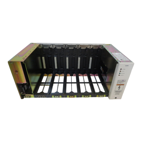
Configuration Figure 2-2 shows an isometric view of the GPS 2408 plant with
the 7-foot frame. Figure 2-3 is an isometric view of the 42″
frame. The plant requires front access only for installation and
maintenance, allowing installation against walls, in
back-to-back line-ups, or in line-ups with other cabinets. System
components are mountedin the tophalf of aseismic network bay
frame. The plant is composed of an ac input panel, rectifier
shelves and rectifiers, converter shelves and converters, dc
distribution panels, and battery connection panels. These
components are described in the following paragraphs.
Specifications for the plant, rectifiers, and converters are given
in tables at the end of this section.
Figure 2-2: Isometric View of the GPS 2408 7-foot Plant Configuration

Lucent Technologies Galaxy Power System 2408
2 - 4 Product Description Issue 2 September 1998
Figure 2-3: Front and Side Views of the GPS 2408 42-inch Plant Configuration

Lucent Technologies Galaxy Power System 2408
Issue 2 September 1998 Product Description 2 - 5
Plant
Specifications
Table 2-A: GPS 2408 Plant Specifications
Plant input voltage
3-phase, 3-wire wye or delta (Note 1)
176-264 Vac phase-phase or
individual 176-264V feed to
rectifiers
Plant input current 75 amperes per phase, 3-phase bulk
feed (Note 2)
Plant output voltage ranges 24-volt output: 22-28 Vdc
48-volt output: 48-52Vdc
Plant output current ranges 24-volt output: 0 to 800 amperes
(Note 3)
48-volt output: 0 to 17 amperes
DC distribution at 24 volts 42 plug-in slots for KS-23616 circuit
breakers or AT-type fuses.
See Tables 3-G and 3-H.
DC distribution at 48 volts
2 plug-in slots for KS-23616 circuit
breakers.
4 plug-in slots for WP-90247 (GMT)
fuses.
See Table 3-J.
Maximum discharge
current 1000 amperes
Maximum recharge current Installed plant 24-volt rectifier
capacity minus plant 24-volt load
Low voltage battery
disconnect
Configurable threshold. See Figure
5-9. Refer to Galaxy RC product
manual for more information.
Altitude -50 to 4000 meters (Note 4)
Operating ambient
temperature 0°C to 45°C
Operating relative
humidity 5% to 95%

Lucent Technologies Galaxy Power System 2408
2 - 6 Product Description Issue 2 September 1998
Note 1: AC service for this plant must be provided with
a 208/220/240-volt, 3-phase, 3-wire plus protective earth
ground service (3W+PE).
Note 2: The current is based on three rectifiers per phase
operating at full load and 176Vac 3-phase input.
Note 3: The 24-volt current capacity must be reduced by the
current required to operate the ES682H converters (Table 2-E).
Note 4:For altitudes between 1500 and 4000 meters, de-rate the
maximum temperature by 0.656°C per 100 meters.
GalaxyRectifier
Controller The Galaxy Rectifier Controller (Galaxy RC) monitors and
controls the GPS 2408. System operating voltages, alarm
thresholds, and other configuration parameters are managed by
the Galaxy RC. The Galaxy RC can monitor and control up to 24
rectifiers and up to 8 converters via an isolated digital RS-485
serial control interface.
Radiated and conducted
emissions C.I.S.P.R. 22 Class A
Electromagnetic immunity 3 volts/meter
Earthquake rating Zone 4, upper floors
Approval marks UL, CUL
CE Marked
CE marked to demonstrate
compliance with the European
Union’s electromagnetic
compatibility and low-voltage
directives.
Width 25.5 inches (648 mm)
Height 84 inches (2134 mm) or
42 inches (1067 mm)
Depth 19 inches (485 mm)
Weight 380 pounds
Table 2-A: GPS 2408 Plant Specifications

Lucent Technologies Galaxy Power System 2408
Issue 2 September 1998 Product Description 2 - 7
The Galaxy Rectifier Controller is mounted on the inside front
door of the GPS 2408 plant with the control panel visible on the
front of the door. See Figure 2-4.
NOTE Configuration of the Galaxy Rectifier Controller must be
determined by personnel qualified and trained to configure
your plant. Please contact your local Lucent Technologies
Power Systems representative for the proper configuration.
The Galaxy Rectifier Controller product manual (Select Code
167-792-170) is furnished with every GPS 2408 plant. Refer to
this manual for information regarding configuration and
operation.
The Galaxy Rectifier Controller (Galaxy RC) provides the GPS
2408 plantwith a wide range of control and monitoringfeatures.
The basic controller consists of a Control Board (BMY1) and a
Control Panel (BMW1). These boards are mounted
independently within the plant enclosure in a manner defined in
the particular GPS series plant documentation. The controller
issues only Power Major (PMJ) and Power Minor (PMN) office
alarms off the Control Board TB1. The controller can be
supplemented with a Enhanced Relay Board to provide two
additional PMJ alarms, two additional PMN alarms, control
inputs, and twelve other discrete alarms.
Circuit Boards Control Board (BMY1)
The Control Board monitors and controls the GPS 2408,
including rectifiers, converters, distribution, and contactors. It is
the intelligence and memory of the system.
The Control Board has a 6-position terminal block (TB1) for
user interface to the Power Major and Power Minor alarm relay
contacts. All user output relays are isolated Form-C or transfer
type, a combination of normally open and normally closed
contacts with the middle or return contact in common. The
de-energized state of these relays is the alarm condition. While
the plant is operating normally, the alarm relays are energized
and the normally closed contacts are open; an alarm condition
results in a closure of the normally closed contact to the return
contactand anopening of thenormally opencontact tothe return
contact.

Lucent Technologies Galaxy Power System 2408
2- 8 Product Description Issue 2 September 1998
TB2 is a 6-position terminal block for user interface to provide
input signals for optional Rectifier On/Standby, Rectifier
Holdoff, and Off-Line-Equalize Interlock features.
TB4 is a 6-position terminal block for user interface to an
optional thermistor or 210E thermal probe expansion module
system for battery thermal slope/step compensation.
Control Panel (BMW1)
The Control Panel interfaces with the control board via a 26-pin
ribbon, which is designated J1. It provides comprehensive user
interface with the Galaxy RC. It isused to view plant voltage and
load, configure thresholds and parameters, view active alarms,
and initiate certain plant operations. This interface consists of a
4-digit, 7-segment display, 16 keys, and 18 LEDs. The keys and
LED displays are defined and explained in the Galaxy RC
product manual.
Fuse Board (BNA1)
The Fuse Board serves as the interface between the plant and the
controller. It provides all the fused power required by the
controller and contactor drive boards. It also supplies fuse alarm
and circuit breaker alarm information to the controller.
F01 through F12 are 1-1/3A fuses. The fuses are grouped to
provide eithera major or minor fuse alarm to the controllerwhen
blown. MNF (minor fuse alarm) consists of alarms F1 through
F6. MJF (major fuse alarm) consists of alarms F7 through F12.
Enhanced Relay Board (BMU1)
The Enhanced Relay Board is an optional board for the Galaxy
RC. When this optional board is added to a basic system, it
provides afull set of office alarm contacts and several additional
plant alarm input signals.
The Galaxy RC can monitor and control up to 24 rectifiers and
up to 8 converters via an isolated digital RS-485 serial control
interface.

Lucent Technologies Galaxy Power System 2408
Issue 2 September 1998 Product Description 2 - 9
Figure 2-4: Galaxy Rectifier Controller in the GPS 2408 Plant
Inside View of Front Door
Front View of Control
Panel (BMW1)
Control Board
(BMY1)
Fuse Board (BNA1)
Enhanced Relay
Board (BMU1)
Sheet Metal Cover
+
MINMAJ NORM
STATUS LAMP
TEST
VIEW ACTIVE
GALAXY RECTIFIER CONTROLLER
ALARM
ACO
Lucent
ALARMS
ESCAPEDEFAULT
CONFIGURE ENTER
AMPS
VOLTS
OFF-LINE
EQUALIZE
PLANT VOLTAGE
THERMAL
COMPENSATION
FLOAT
BOOST
BD BATT DIST RECT CTLR AC
This manual suits for next models
1
Table of contents
Other Lucent Technologies Power Supply manuals

Lucent Technologies
Lucent Technologies Galaxy Power System 4812 User manual

Lucent Technologies
Lucent Technologies Lineage 2000 User manual

Lucent Technologies
Lucent Technologies CIB 2866 User manual

Lucent Technologies
Lucent Technologies J85500Q-1 User manual

Lucent Technologies
Lucent Technologies INDeX 20DS Turret User manual

Lucent Technologies
Lucent Technologies CPS4000 User manual

Lucent Technologies
Lucent Technologies Galaxy Power System 4824 User manual

Lucent Technologies
Lucent Technologies Lineage 2000 User manual

Lucent Technologies
Lucent Technologies Galaxy 4804AP User manual

Lucent Technologies
Lucent Technologies Galaxy 4848/100 User manual