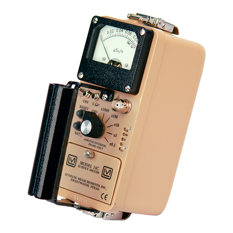
LUDLUM 3-98 User manual

LUDLUM MODEL
3-98
SURVEY
METER
Revised September
1992
Serial No.
97869
and Succeeding
Serial Numbers
LUDLUM MEASUREMENTS,
INC.
501
OAK
ST.,
P.O.
BOX
810
SWEETWATER,
TX
79556
91
51235-5494
FAX:
91
51235-4672

h
1
8
HVE
@
HVI
0
e
MODEL
3-98
SURVEY METER
LUDLUM MEASUREMENTS,INC.
SWEETWATER, TEXAS
\c
I

M3-98
Survey Meter
TABLE
OF
CONTENTS
1
.
GENERAL
.........................................................
1
2
.
SPECIFICATIONS
....................................................
1
3
.
DESCRIPTION OF CONTROLS AND FUNCTIONS
...............................
1
4
.
OPERATINGPROCEDURES
.............................................
2
5
.
CALIBRATION
......................................................
2
5.1
Detector OperatingPoint
..............................................
2
5.2 Calibrating CPM Meter Dial
............................................
3
6
.
MAINTENANCE
.....................................................
3
7
.
THEORYOFOPERATION
...............................................
4
7.1INPUT
.........................................................
4
7.4AUDIO
.........................................................
4
7.6SCALERANGING
..................................................
4
7.2AMPLIFIER
......................................................
4
7.3DISCRIMINATOR
..................................................
4
7.5 DIGITAL ANALOG CONVERTOR
.......................................
4
7.7METERDRIVE
....................................................
4
7.8METERCOMPENSATION
............................................
4
7.9 FASTBLOW TIME CONSTANT
.........................................
4
7.11 LOW VOLTAGE REFERENCE
.........................................
5
7.12 HIGH VOLTAGE SUPPLY
............................................
5
7.10LOWVOLTAGESUPPLY
............................................
4
PARTSLIST
...........................................................
6
Model 3-98 Survey Meter
................................................
6
Circuit Board. Drawing 363
X
525
........................................
Chassis Wiring Diagram. Drawing No
.
363
X
582
..............................
6
7
Calibration Board. Drawing No
.
363
X
528
..................................
7
DRAWINGSANDDIAGRAMS
...............................................
9
page
i

M3-98
Survey
Meter
The Model 3-98
is
a portable survey instrument
with four linear ranges reading up to
500,OOO
CPM.
Theinstrumentfeaturesan internalpancaketube along
with the capability of utilizing an external probe by a
switch
on
the front panel labeled INT/EXT. Separate
high voltage adjustments for the internal and external
probes are provided. The high voltage power supply
is regulated and adjustable from 200 to loo0 volts.
Theunit body is made of cast aluminum, includingthe
meter housing. The can
is
0.090" aluminum. Other
operatingfeaturesof theinstrumentincludea unimorph
speaker mounted to the instrument can with an audio
ON-OFF capability, fast-slow meter response, meter
reset button, and a six-positionswitch for selecting
battery check or scalemultiplesof XO.
1,
X1, X10, and
X100. Each range multiplier has its own calibration
potentiometer.
Any G-M probe offered by the company will
operate
on
this
unit
as
well
as
many of the scintillator
type detectors. The externalhigh voltageis factory set
for 900 volts. For special requirements, it
may
be
adjustedfor operationwithany
G-M
or scintillatortube
between 200 and lo00 volts.
The
unit
is operated with two
"D"
cell flashlight
batteries for operation from 150°F to approximately
32°F. For temperature operation
to
O"F, either very
fresh alkaline or rechargeable NiCd batteries may
be
used.
Battery drain averages 17 milliamperes.
0
POWER: two standard
"D"
sizebatteries
0
RANGES: four linear range multiples of
XO.l, X1, X10, and X100; typically used in
combinationwith the 0-5k CPM meter dial,
0-500,OOO
CPM
is
achieved with the range multiplier.
0
l"UT
SENSITIVITY: 30 millivolts,
(f
10
mV)
0
AUDIO: built-in unimorph speaker with an
0
HIGH
VOLTAGE:externallyadjustablefrom
0
RESPONSE: Four or twenty-twoseconds for
0
LINEARJTY: plus or minus
5%
full scale
0
BATTERY
LIFE:
exceeds 600 hours with a
ON-OFF switch
200 to
lo00
volts
90%of final meter reading
fresh set of alkaline
"D"
cell batteries
BATTERY DEPENDANCE: Instrument
calibration change less than 3%within battery check
limits
on
meter
METER: lmA, 2 1/2-inchscale, with pivot-
and-jewel suspension
METER COMPENSATION: temperature
compensationis provided by thermistors
on
the Main
Board CONNECTOR: Series "C", 706 UIG; BNC
or MHV
may
also be provided
0
SIZE: 10.67cm (4.2")H X 8.9cm (3.5")W
X
21.6cm
(8.5")L,
exclusive of handle
WEIGHT: 1.36kg
(3
lbs.) less detector and
batteries
FINISH:
drawn-and-cast aluminum, with
computer-beigepolyurethaneenamel and silk-screened
nomenclature
3.
DESCRIPT.ION
OF
CONTROLS
AND
FUNCTIONS
0
Range Multiplier Selector Switch: A six-
position switch marked OFF, BAT, X100, X10, X1,
XO.
1.
Turning the range selector switch from OFF to
BAT position provides the operator a battery check of
the instrument.
A
BAT check scale
on
the meter
providesa visual means of checking the battery status.
Moving the range selector switch to one of the range
multiplier positions (XO.
1,
X1, X10, X100) provides
the operator with an overall range of 0-5OOk CPM
(typical meter dials is
0-5k
CPM). Multiply the scale
reading by the multiplier for determining the actual
reading.
0
AUD ON-OFF' Toggle Switch:
In
the ON
position, the switch energizes the unimorph speaker,
located
on
the left side of the instrument. The
frequency of the clicks is relative to the rate of the
incoming pulses. The higher the rate, the higher the
audio frequency. The audio should be turned OFF
when not required to reduce battery drain.
F-S
ToggleSwitch: Providesmeter response.
Selecting the fast, "F", position of the toggle switch
provides 90% of the final meter reading in four
seconds.
In
slow,
"S",
position,
90%
of the final
meter reading takes 22 seconds. In "F"position there
is fast response and large meter deviation. In
"S"positionthere is a slow response and damped meter
deviation.
RESET Pushbutton: When depressed,
provides a rapid
means
to drive the meter to zero.
M3-98
Survey Meter
INTEXT
Switch:
Atwo-positionswitch
used
to alternatebetween the internal pancake tube and the
external probe.
In
the INT position, the internal tube
is utilized.
In
the EXT position, the external probe is
Range
Calibration Adjustments:
Recessed
utilized. potentiometers located under the calibrationcover,
on
the right side of the front panel. These adjustment
the high voltage from
200
to
lo00
volts. The high controls allow individual calibration for each range
multiplier.
voltage settingmay be checked at the probe connector
with an appropriatevoltmeter.
H.V. Adjustment:
Provides a means to vary
4.
OPERATINGPROCEDURES
J
Note: To open the Battery Lid, twist the lid
To close, twist
button counterclockwise 114 turn.
clockwise 114 turn.
0
Open
the Battery Lid and install
two
"D"
size batteries. Note
(+)
(-)
marks
on
the inside
of the lid. Match the battery polarity to these
marks.
J
NOTE: Center post of flashlight battery is
positive. Close the battery box lid.
0
Switch the range switch to BAT. The
meter shoulddeflectto thebattery checkportionof
the meter scale.If the meter does not respond,
recheck that the batteries have proper polarity.
0
Turn the INT/EXT switch to EXT.
0
Connect a detector to the M3-98.
0
Turn the instrument range switch to
X100. Expose the detector to a check source.
The speaker should click with the AUDIO ON-
OFF
switched to ON.
0
Move
the
range switch
to
thelower scales
until a meter reading is indicated. The toggle
switch labeled F-S should have
fast
response
in
"F"andslow response in
"S".
o
Depress the
RES
switch. The meter
should zero.
0
Turn the INT/EXT switch to INT and
hold the check source to the bottom of the
can
until a meter reading is indicated.
JNOTE:
To
assureproper operationof the instrument
between calibrations, an instrument operational check
should
be
performed prior
to
use. A reference reading
with a check source should be obtained at the time of
initialcalibrationor
as
soon
as
possibleafterwards, for
confirming correct operation. Confirm the proper
reading
on
each scale.
If instrument fails to fall within
f20%
of proper
reading, it shouldbe sent in to a calibrationfacility for
recalibration.
5.
CALIBRATION
5.1
Detector ODeratine Point
CAUTION: The detector operating voltage is
connected to both detectors at all times, regardless of
which position the detector INT/EXT switch is set.
The maximum operating voltage for the internal GM
detector is lo00 VDC; therefore, the external detector
operating voltage must be kept below 1000VDC.
Switch the INT/EXT switch to the INT position
and
adjust the HVE control for 900 volts at the
instrument connector.
J
NOTE: Measure High Voltage with a Model
500
pulser or a High Impedance voltmeterwith a high
meg probe.
If
one
of these is not available, use a
voltmeter with a minimum of lo00 megohm input
resistance.
For external G-M detectorapplications,the power
supply may be adjusted for 450-550 volt and 900 volt
G-M tubes. Followthe above procedure, only set the
supply at the new operating voltage.
For scintillationcounters, connect the scintillator.
Expose the unit to a source and develop an operating

M3-98
Survey Meter
voltage versus count-rate plot.
voltage at the flattestportion of this curve.
5.2
Calibrating CPM Meter Dial.
To
calibratethe CPM scale, a Ludlum Model 500
Connect the pulse generator to the instrumentand
Set the operating adjust the pulse frequency
to
provide a 4/5-scale
deflection
on
the Xl00 range (400,000 CPM). Adjust
the Xl00 range calibration potentiometer
as
required.
Adjust the pulse frequency
to
a
1/5scale deflection
on
the XlOO range (l00,OOO CPM) and confirm that the
meter indicates
&lo%
of
incoming pulses. Decrease
the pulse frequency by decades and adjust each range
calibrationpotentiometeraccordingly.
pulse generator is required.
Instrument maintenance consists
of
keeping the
instrumentclean andperiodicallycheckingthe batteries
and the calibration,
An
instrument operational check should be
performed prior to each use by exposing both the
internal and external detectorsto a
known
source and
confirmingthe proper reading
on
each scale.
Recalibration should be accomplished after any
maintenance or adjustment of any kind has
been
performed
on
the instrument. Battery replacementsare
appropriateregulatoryagenciesregulationstodetermine
required recalibrationintervals.
The batteries should
be
removed and the battery
contacts cleaned
of
any corrosion at least every three
months.
If
the instrumenthas
been
exposed to a very
dusty or corrosive atmosphere, more frequent battery
servicing should be used.
Use a spanner wrench to unscrew the battery
contact insulators, exposing the internal contacts and
battery springs. Removing the handle will facilitate
not considered to be maintenanceand
do
not normally
require the instrumentto
be
recalibrated.
Ludlum Measurements recommends recalibration
at intervals
no
greater than one year. Check the
access to these contacts.
NOTE
NEVER STORE THE INSTRUMENTOVER
30
DAYS WITHOUT REMOVING BATTERIES.
ALTHOUGH THIS INSTRUMENT WILL OPERATE AT VERY HIGH AMBIENT TEMPERA-
rums,
BATTERY
SEAL
FAILURE
CAN
OCCUR
AT
TEMPERATURES
AS
LOW
AS
1000
FAHRENHEIT.

M3-98
Survey Meter
7. THEORY OF OPERATION
7.1
INPUT
The external detector pulses are coupled from the
detector through C3 to emitter follower
45.
R10 and
R20
provide bias. R32 protects
45
from input shorts.
R38 couples the detector to the high voltage supply.
The internaldetector (Vl)pulses are coupled from
the detector through C27 to emitter follower
47.
R45
limits the current to V1.
R21
and R41 provide bias to
47. R40 protects 47from input shorts. R39 couples
V1 to the high voltage supply.
The internal detector is used only when the
INT/EXT switch
is
in
the INT position.
In
the EXT
position, the external detector is used. When in the
EXT position, P1-13 is grounded turning off 46,
allowing the pulses from
45
to pass
on
to the
amplifier. P1-14 is opened allowing R46 to bias 49,
pulling the pulses from the base of 47 to ground and
blockingthemfrom the amplifier.
In
theINT position,
P1-14 is grounded turning
on
49, allowing the pulses
from 47 to pass
on
to the amplifier. P1-13 is opened
allowing R47 to bias 46, pulling the pulses from the
base of
45
to ground and blocking them from the
amplifier.
7.2
AMPLIFIER
A
self-biased amplifierprovidesgain inproportion
to R33 dividedby R6 for the external detectorand R33
divided by R44 for the internal detector. Transistor
(pin 6 of U4) provides amplification. Pin 12,15of U4
are coupled as current mirror to provide a load for pin
6 of U4. The output self-biases to 2
Vbe
(approximately 1.4 volts) at pin
7
of
U4.
This
providesjust enough bias current through pin 6 of U4
to conduct all of the current from the current mirror.
Positivepulses frompin 7 of U4 are coupled to the
discriminator.
10of U6 turns
on
oscillator U2, which drives the can
mounted unimorph. Speaker tone is set by R13,C12;
duration by R36,C23.
7.5 DIGITAL ANALOG CONVERTOR
Pins 10-15of U1 are coupled as a current mirror.
For each pulse of current through R9, an equal current
is delivered to C22.
This
charge is drained off by
R42. The voltage across C22 is proportional to the
incoming count rate.
7.6 SCALERANGING
Detectorpulses from the discriminatorare coupled
to univibrator pin
5
of U6. For each scale, the pulse
width of pin 6 of U6 is increased by a factor of 10
with the actual pulse width being controlled by the
front panel calibration controls
and
their related
capacitors.
This
arrangement allows the same current
to be delivered to C22 by one-tenth of a count
on
the
X.l range as
100
counts
on
X1K range.
7.7 METER DRIVE
The meter is driven by the emitter to 43, coupled
as a voltage followerin conjunctionwith pin
1
of U3.
For Battery Test, the voltage follower is bypassed and
the meter movement is directly coupled to the battery
through R26.
7.8 METER COMPENSATION
When the unit is provided with a high torque meter
movement, with 1.2 volt drive, a temperature
compensation circuit is provided
on
the Main Circuit
board; components R15,R17
&
R23.
7.3 DISCRIMINATOR 7.9 FASTBLOW TIME CONSTANT
Comparator U5 provides discrimination. The
discriminator
is
set by the voltage divider, R8 and R5,
coupled to pin 3 of U5. These pulses are coupled to
pin
5
of U6 for meter drive and pin 12 of U6 for
audio.
For slow time constant, C29 is switched from the
output of the meter drive to parallel C22.
7.10
LOW
VOLTAGE SUPPLY
7.4
AUDIO
Discriminatorpulses are coupled to univibratorpin
12of U6. Front panel audio ON-OFF selectorcontrols
the reset at pin 13of U6. When
ON,
pulses from pin
Battery voltage is coupled to U8 and associated
components (a switching regulator) to provide
5
volts
at pin
5
to power all logic circuits. Unregulated
battery voltage is used to power the meter drive (43)
and the high voltageblocking oscillator
(42).

M3-98
Survey Meter
7.11 LOW VOLTAGE
REFERENCE
U7
providesa 1.22voltprecisionreferencefor
HV
supply
-
7.12 HIGH VOLTAGE
SUPPLY
High voltage is developed by blocking oscillator
Q2-T1 and rectified by voltage multiplier
CRl,CR2,
CR3,
and
CR4.
Output voltage increases as current
through Q1 increases, with maximum output voltage
with Q1 saturated.
High voltage is coupled back through R12 to
opamp pin
6
of
U3.
R2
completes the high voltage
circuit to ground. High voltage output is set by
R4
(HV Set), which sets bias of pin
5
of
U3.
During
stable operation, the voltage at pin
6 of
U3
will
equal
the voltage at pin
5
of
U3.
Pin
7
of
U3
will cause
conductionof Q1 to increase
or
decreaseuntil the high
voltage
seeks
a level
of
stability.

M3-98
Survey Meter
PARTS LIST
Ref.
No.
Description
Part
No.
Model
3-98
Survey Meter
UNIT Completely Assembled Model
3-98 Survey Meter 48-1135
CircuitBoard, Drawing
363
X
525
BOARD Assembled CircuitBoard 5363-672
0
CAPACITORS
c1
c2
c3
c5
C6-C7
C8
c9
c10
c11
c12
C13
C14
C15
C16-Cl7
C18
c19
c20
c2
1
c22
C23
C24
C25
C27
C29
C30
O.O015pF, 3kV, C
O.OlpF, 100V, C
lOOpF,
3kV, C
220pF, lOOV, C
0.0015pF, 3kV, C
0.001pF, lOOV, C
lOOpF, lOV, DT
lOOpF,
3kV, C
0.0015pF, 3kV, C
470pF, 100V, C
O.OlpF, lOOV, C
lpF, 35V, DT
O.lpF, lOOV, C
lOOpF, lOV, DT
300pF, 100V, C
lOpF, 20V, DT
220pF, 100V, C
lOOpF, 100V, C
lOpF, 20V, DT
O.OlpF, lOOV, C
lOOpF, lOV, DT
O.lpF, 35V, DT
100pF,3kV, C
47pF, 16V,DT
O.lpF, 35V, DT
0
TRANSISTORS
Q1
2N3904
42 MPS6534
43 2N3904
44 MPSU51
WQ8 2N3904
0
INTEGRATED
CIRCUITS
u1
CA3096
u2 ICM7555
u3 TLC27M7IP
u4 CA3096
04-5518
04-5523
04-5532
04-5530
04-55
1
8
04-5519
04-5576
04-5532
04-55
1
8
04-5555
04-5523
04-5575
04-5521
04-5576
04-553
1
04-5592
04-5530
04-5527
04-5592
04-5523
04-5576
04-5574
04-5532
04-5550
04-5574
05-5755
05-5763
05-5755
05-5765
05-5755
06-6023
06-6136
06-6023
06-6248
Ref.
No.
Description
U5 TLC372IP
U6 CD4098BE
US MAX63
1
u7 LM385Z-1.2
0
DIODES
CR1-CR4 1N4007
CR5 1N4148
RESISTORS
R1
R2
R3
R4
R5
R8
R9
R10
R11
R12
R13
R14
R16
R17
R18
R19
R2o-R21
R22
R24
R25
R26
R27
R28
R29
R30
R3
1
R32
R33
R34
R35
R36
R37
R3
8
R39
R40
R4
1
R42
R44
R6-R7
1M
lM, 1/8W,
1%
1Ok
22k
1Ok
4.7k
43k
33k
l00k
1Ok
1G
470k
1Ok
lk
301 OHM,
1%
47k
lk
lOOk
1Ok
200 OHM
2.2k
2.37k,
1%
22k
100OHM
8.2k
1OOk
lk
10k
82k
1Ok
l00k
2.7M
lk
1M
33k
1Ok
lOOk
180k
4.7k
Part
No.
06-6265
06-6066
06-6249
05-5808
07-6274
07-6272
10-7028
12-7609
10-7016
10-7070
10-7016
10-7014
10-7057
10-7019
10-7023
10-7016
12-7686
10-7026
10-7016
10-7009
12-7855
10-7020
10-7009
10-7023
10-7016
10-7006
10-7012
12-7648
10-7070
10-7004
10-7015
10-7023
10-7009
10-7016
10-7022
10-7016
10-7023
10-7009
10-7009
10-7028
10-7019
10-7016
10-7023
10-7068
10-7014

M3-98
Survey Meter
R47 1OOk 10-7023
MISCELLANEOUS
R48 1OM 10-703
1
P3 CONN-640456-5
THERMISTORS
MTAlOO 13-8057
P4 CONN-640456-4
R15 R1006-98.4-59-D
1
07-6332 MTAlOO 13-8088
R23 R1006-98.4-59-D1 07-6332
Chassis Wiring Diagram, Drawing
No.
363
INDUCTORS
X
582
AUDIO
L13 470UHY 21-9600
UNIMORPH 60690
21
-925
1
DS
1
TRANSFORMERS
CONNECTOR
T1 L8050 40-0902
J1 CONN-1-640442-6
MISCELLANEOUS
*
P1
P2
*
*
RECEPTACLE (8 ea)
Cloverleaf
011-6809
MTAl00
MTAlOO
LRG. MOLEX PIN
16060007
CONN-1-640456-6
CONN-640456-2
JACK-TEST
1128-09-0319
18-8771
13-8134
13-8073
18-8792
J2
53
J4
J5
s1
18-8806
MTAlOO
MTAlOO
MTAlOO
MTAlOO
CONN-640442-2
CONN-640442-5
CONN-640442-4
RECPT-UG706/U
"
C
"
u,G
CalibrationBoard, Drawing
No.
363
X
528
s3-s4
.
SWITCHES
13-8187
13-8178
13-8140
13-8170
13-7751
Centerlab PA600-210 08-6501
7101-SYZ-QE 08-65
11
55D36-01-2-AJN 08-6514
s5
30-1 P/B 08-6517
BOARD Completely Assembled
BATTERY
Calibration Board 5363-674
B
1
-B2 "D" Duracell Battery 21-9313
CAPACITORS
0
DETECTOR
c1
0.047pF lOOV C X7R 04-5565
c2 O.OO47pF lOOV C X7R 04-5570
v1
GM TUBE-LND73
11
01-5008
RESISTORS
0
MISCELLANEOUS
R1-R2
1
Meg Trimmer
R3 lOOk Trimmer
R4
1
Meg Trimmer
R5 lOOk Trimmer
R7 1OOk Trimmer
RESISTOR NETWORK
RN1
NETWORK-1Ok SIP
8PIN
*
09-6814
09-6813
09-6814
*
09-6813
09-6813 M1
*
*
12-7720
*
*
M3-98 BATTERY BOX LID
WILATCH SET 9363-215
BATTERY CONTACT
PORT BEZEL
SET 40-1707
FRONT PANEL ASSY 4363-188
M3-98 CAN
ASSEMBLY 4363-737
M3-98 CASTING 9363-739
M3-97/3-98 MAIN
HARNESS 8363-700
PORTABLE KNOB 08-6613

M3-98
Survey Meter
PROBE KNOB-
MS
91528 086606
PORT BEZEL GLASS
METER MOVEMENT
PORTABLE METER
WIO SCREWS
4363-352
(1mA)
15-8030
FACE
7363-136
HARNESS-PORT
CAN
WIRES
8363-462
BATTERY LID
WILATCHSET
PORT. LATCH KIT
PORT. CALIB. COVER
PORT. HANDLE (ROLLED)
PORT HANDLE FOR CLIP
REPLACEMENT CABLE
Model
3
9363-198
WIO BAR. LID
4363-349
WISCREWS
9363-200
WISCREWS
7363-139
WISCREWS
7363-203
(STD
39") 40-1004
CLIP
(44-3
TYPE)
WISCREWS
7a32-026-01
CLIP
(44-7
TYPE)
WISCREWS
701om741
CLIP
(44-6
TYPE)
WISCREWS
701-1

M3-98
Survey Meter
DRAWINGS
AND
DIAGRAMS
Main Circuit Board, Drawing 363
x
525
Main CircuitBoard Component Layout, Drawing 363
x
526
CalibrationBoard, Drawing 363
x
528
Calibration Board Component Layout, 363
x
529
Wiring Diagram, Drawing 363
x
582

SIGNAL
‘::::”
>f
EXTERNAL1
R38
In
‘1
-13
I
-14
+
m
1
I
I
R28
t5V
R27
<
2%
<
2N3984
I
SIGNAL
FLYING
07
2N3904
iiQ
R44
4.7K
IBBPF
IINTERNALI
LEADxy,/7?
33K
;;;
1
RIS
1K
R4B
1011
I
REVISIONS
[
EFF
I
*uinmIiv
I
ZDNE
I
LTR
I
DESCRIPTION
I
DATE IAPPROVI
>PI
-8
Rll
301
LX
113U
’
R15
R23
>
P1
-11
8:+5V ,4=CND
u2
113117555
4-
RESET
cv
our
>
P2
-2
P2
-1
rsv-
P1
-1
IBBV
+PI
-a
16-+6V
,I=CND

BOARD
DIMENSIONS
~
WIDTH
=5,147"
HEIGHT=2
,810"
MOUNTING HOLE
LOCATIONS
:
1
I
X=0,140"
Y=0,734"
2
I
X=4 ,837"
Y=0,250"
3,
X=4 ,897"
Y=2
,560''
4,
X=O ,140"
Y=2,076"
0.0-6iWF

.6V
P3
-3
)
PI
-I
pa
-2
m
P3
-5
<
R4
XI0
in
P3
-4
R3

c2
c1
P3
P4
R7
R5
R3
R4
R2
R1
I
DESC:-COMPONENT OUTLINE
I
MODEL:
3-97
&
3-98
PART
#:
5363-674
I
DWN:
CKB
I
DATE:
09/11/92
I
1
DSGN:
I
DATE:
I

I
REVISIONS
I
EFF
I
AUTHORITY
I
ZONE
I
LTR
I
DESCRIPTlON
I
DATE
IAWROVE
J3
CALIBRATION
BOARD
Jt
MIN
WARD
6363-672
16
PIN
SIP
OFF
d
--
T
El
FAST
s3
bDw
RESWNSE
IB
tl.22V
I
J2
WIN BOARD
5363-672
2
PIN SIP
rnl
I
LrlIlKYIPH
V1
PANCAKE
Gn
TUBE
SIWAL
FLYING
LEAD TO MAIN
BOARD
5363-672
[INTERNAL
PROBE1
SIGNAL FLYING
LEAD TO MAIN
BOARD
5363-672
[EXTERNAL PROBE1
U
J4
CALIBRATION BOARD
5363-674
1
PIN SIP
I
LUDLUn nEASUREIENl3
INC
I
UPDATED
-
TITLE
~
UIRINC
DIAGRAM
EKU
cHK
Rd.
I
SHEET
1
OF
1
ii-scp-sa
58363733
11
:30:41
Table of contents
Other LUDLUM Measuring Instrument manuals

LUDLUM
LUDLUM Model 6 User manual

LUDLUM
LUDLUM 2241-3RK2 User manual

LUDLUM
LUDLUM 2401-EC User manual

LUDLUM
LUDLUM 2241 User manual

LUDLUM
LUDLUM 14C User manual

LUDLUM
LUDLUM 177-56 User manual

LUDLUM
LUDLUM 2221 User manual

LUDLUM
LUDLUM 12-4 User manual

LUDLUM
LUDLUM MODEL 3 User manual

LUDLUM
LUDLUM MODEL 19 User manual

LUDLUM
LUDLUM 26-1 User manual

LUDLUM
LUDLUM MODEL 2241-2 User manual

LUDLUM
LUDLUM 9DP-1 User manual

LUDLUM
LUDLUM 2241-2i User manual

LUDLUM
LUDLUM 2363 User manual

LUDLUM
LUDLUM 3001 User manual

LUDLUM
LUDLUM 192 User manual

LUDLUM
LUDLUM 2241-3RK User manual

LUDLUM
LUDLUM 19A User manual

LUDLUM
LUDLUM 9-3 User manual