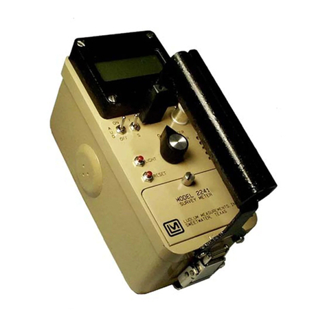
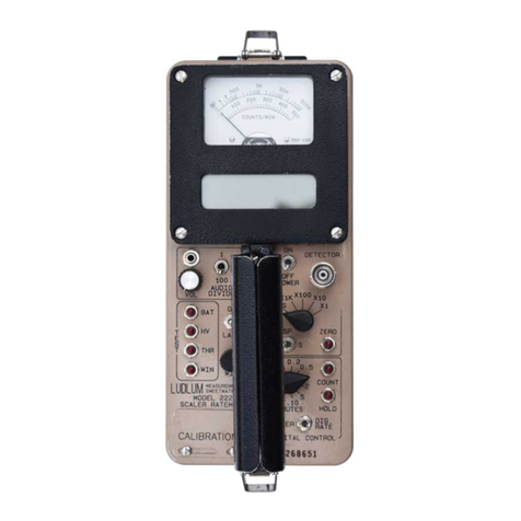
LUDLUM 2401-EC User manual

LUDLUM MODELS 2401-EC, 2401-EW,
2401-EC2 AND 2401-P
POCKET SURVEY METERS
March 2015
Serial Number 137772 and Succeeding
Serial Numbers

LUDLUM MODELS 2401-EC, 2401-EW,
2401-EC2 AND 2401-P
POCKET SURVEY METERS
March 2015
Serial Number 137772 and Succeeding
Serial Numbers

STATEMENT OF WARRANTY
Ludlum Measurements, Inc. warrants the products covered in this manual to be free of
defects due to workmanship, material, and design for a period of twelve months from the
date of delivery. The calibration of a product is warranted to be within its specified
accuracy limits at the time of shipment. In the event of instrument failure, notify Ludlum
Measurements to determine if repair, recalibration, or replacement is required.
This warranty excludes the replacement of photomultiplier tubes, G-M and proportional
tubes, and scintillation crystals which are broken due to excessive physical abuse or used
for purposes other than intended.
There are no warranties, express or implied, including without limitation any implied
warranty of merchantability or fitness, which extend beyond the description of the face
there of. If the product does not perform as warranted herein, purchaser’s sole remedy
shall be repair or replacement, at the option of Ludlum Measurements. In no event will
Ludlum Measurements be liable for damages, lost revenue, lost wages, or any other
incidental or consequential damages, arising from the purchase, use, or inability to use
product.
RETURN OF GOODS TO MANUFACTURER
If equipment needs to be returned to Ludlum Measurements, Inc. for repair or calibration, please send to
the address below. All shipments should include documentation containing return shipping address,
customer name, telephone number, description of service requested, and all other necessary information.
Your cooperation will expedite the return of your equipment.
LUDLUM MEASUREMENTS, INC.
ATTN: REPAIR DEPARTMENT
501 OAK STREET
SWEETWATER, TX 79556
800-622-0828 325-235-5494
FAX 325-235-4672


Ludlum Measurements, Inc. March 2015
Table of Contents
Introduction 1
Getting Started 2
Battery Installation 2-1
Battery Test 2-1
Instrument Test 2-1
Operational Check 2-2
Specifications 3
Identification of Controls and Functions 4
Safety Considerations and Maintenance 5
Environmental Conditions for Normal Use 5-1
Warning Markings and Symbols 5-1
Mica Window Precaution 5-2
Cleaning and Maintenance Precautions 5-2
Maintenance 5-3
Recalibration 5-3
Slide Switches 5-3
Radiation Basics 6
Radiation and Life 6-1
The Unstable Atom 6-2
Radioactive Decay 6-3
Ionizing Radiation 6-4
Measuring Ionizing Radiation 6-5
What are the Health Risks from Ionizing Radiation? 6-6
How Much Ionizing Radiation is Dangerous? 6-7
Background Radiation 6-10
Manmade Radiation 6-11
Protection from Radiation 6-11
Standards and Regulation 6-12
Who is in Charge? 6-12

MODELS2401-EC,2401-EW,2401-EC2 & 2401-P Technical Manual
Ludlum Measurements, Inc. March 2015
Recycling 7
Parts List 8
Models 2401-EC, 2401-EW, 2401-EC2 Survey Meters 8-1
Main Board, Drawing 397 × 75 8-1
Model 2401-P Survey Meter 8-3
Main Board, Drawing 397 × 50 8-3
Drawings and Diagrams 9

MODELS2401-EC,2401-EW,2401-EC2 & 2401-P Section1
Ludlum Measurements, Inc. Page 1-1 March 2015
Introduction
he Model 2401 series of hand-held or “pocket” radiation survey
instruments are designed to quickly and easily measure ionizing
radiation. Different types are available featuring different internal
detectors. These types are distinguished from one another by a
suffix following the “Model 2401” designation. The units are self-contained
and require no external accessories.
This manual applies to the following instruments in the Model 2401 series:
Model 2401-EC - contains an energy-compensated Geiger-Mueller
(GM) tube detector, which measures low levels of gamma radiation.
One or two measurement scales are provided on the meter face (in
addition to the BAT OK range). If two scales are provided, they indicate
exposure rate and count rate. Examples of exposure rate units are
mR/hr and mSv/h, while count rate may be measured in counts per
minute (cpm) or counts per second (cps).
Model 2401-EW - has a thin end-window GM tube detector that
measures alpha, beta, and gamma radiation. The mica window has a
thickness (window area density) of 1.5 to 2.0 mg/cm2. Two
measurement scales may be provided on the meter face, as described
above.
Model 2401-EC2 - contains an energy-compensated GM tube detector.
This is basically the same as the Model 2401-EC, with the capability of
measuring higher levels of gamma radiation with corresponding
measurement scales.
Model 2401-P - employs a full-size “pancake” tube detector (5.1 cm {2
in.} diameter) that can measure alpha, beta, and gamma radiation. One
or two measurement scales may be provided on the meter face in units
of exposure rate and/or count rate, as described above.
Each instrument in the Model 2401 series has a large 6.4 cm (2.5 in.) analog
meter for displaying the radiation level. A three-decade range switch allows
the user to switch among the three ranges (×1, ×10, and ×100).
Sectio
n
1
T

MODELS2401-EC,2401-EW,2401-EC2 & 2401-P
Ludlum Measurements, Inc. Page 1-2 March 2015
A BAT CHECK position on the selector switch allows the meter to show the
battery level. A QUIET position allows the user to turn the click-per-event
audio off. A 9-volt battery powers the unit. Battery life is typically 250 hours
at normal background levels. A steady tone from the audio speaker (whether
in NORMAL or QUIET mode) indicates that the battery needs to be changed;
proper instrument operation is not guaranteed while the steady tone is
present.

MODELS2401-EC,2401-EW,2401-EC2 & 2401-P Section2
Ludlum Measurements, Inc. Page 2-1 March 2015
Getting Started
Battery Installation
Ensure the instrument selector switch is in the OFF position. Remove the
four screws from the back side of the instrument and remove the back
housing. Place a 9-volt battery in battery holder and press onto battery
terminals. Replace the instrument housing and screws.
Caution!
Damage to the mica window on the back side of the Model
2401-P and on the top of the Model 2401-EW may result if
careful instrument handling is not practiced. The window is
very fragile and may be punctured quite easily.
Battery Test
The battery should be checked each time the instrument is turned on. Slide
the selector switch to the BAT CHECK position. Ensure that the meter needle
deflects to the battery check portion on the meter scale. If the meter does
not respond, check to see if the battery has been correctly installed. Replace
the battery if necessary.
Instrument Test
After checking the battery, slide the instrument selector switch to the
NORMAL position. Slide the range switch to the ×1 position. A small meter
needle deflection will likely occur, due to normal background radiation. If
the meter needle deflects past full-scale, slide the range switch to the next
highest range until a reading can be determined. The amount of deflection
will depend upon the particular series of instrument (due to meter scale
differences) and the amount of normal background radiation. The
instrument speaker should emit a frequency (clicks) relative to the increase in
meter reading.
Sectio
n
2

MODELS2401-EC,2401-EW,2401-EC2 & 2401-P Section2
Ludlum Measurements, Inc. Page 2-2 March 2015
Place the instrument selector switch in the QUIET position and note that the
audible clicks are silenced. In order to preserve battery life, it is
recommended that the instrument selector switch be kept in the QUIET
position when the audio function is not needed.
While in an area of normal background radiation, expose the center of the
detector to a check source. Ensure the check source reading is within 20%
of the reference reading obtained during the last calibration.
Note:
The crosshairs above the meter on the black, front panel
indicate the location of the center of the detector. The
exception to this is the Model 2401-P where the center of the
detector is visible on the back side of the instrument.
Once this procedure has been completed, the instrument is ready for use.
Operational Check
To assure proper operation of the instrument between calibrations and
periods of nonuse, an instrument operational check including battery test
and instrument test (as described above) should be performed prior to use.
A reference reading with a check source should be obtained at the time of
initial calibration or as soon as possible for use in confirming proper
instrument operation. In each case, ensure a proper reading on each scale. If
the instrument fails to read within 20% of a proper reading, it should be sent
to a calibration facility for recalibration.

MODELS2401-EC,2401-EW,2401-EC2 & 2401-P Section3
Ludlum Measurements, Inc. Page 3-1 March 2015
Specifications
0
Detector Tubes: GM tubes with different characteristics for various
models as follows:
Model 2401-EC: energy-compensated tube; gamma
Model 2401-EW: end-window tube; alpha, beta, gamma
Model 2401-EC2: energy-compensated tube; gamma
Model 2401-P: standard 5.1 cm (2 in.) diameter
pancake tube; alpha, beta, gamma
Window Area (for Model 2401-P): 79% open protective screen
Active: 15.51 cm2
Open: 12.26 cm2
Sensitivity: typical values with a 137Cs source, as follows:
Model 2401-EC: 1050 cpm per mR/hr
Model 2401-EW: 1050 cpm per mR/hr
Model 2401-EC2: 100 cpm per mR/hr
Model 2401-P: 3300 cpm per mR/hr
Energy Response:
Model 2401-EC: within 20% of true value from 60 keV
to 3 MeV
Model 2401-EW: energy dependent
Model 2401-EC2 : within 20% of true value from 60 keV
to 3 MeV
Model 2401-P: energy dependent
Sectio
n
3

MODELS2401-EC,2401-EW,2401-EC2 & 2401-P Section3
Ludlum Measurements, Inc. Page 3-2 May 2014
Operating Voltage: typically 550 Vdc for peanut tube detectors (as in
Models 2401-EC, 2401-EW, and 2401-EC2); 900 Vdc for pancake tube
detector (as in the Model 2401-P)
Power: one 9-volt battery; typical battery life is 250 hours at normal
background radiation levels.
Response Time: typically 11 seconds or less from 10% to 90% of the
final reading
Accuracy: within 10% of true reading
Meter: 6.4 cm (2.5 in.) arc, 1 mA rugged analog meter
Calibration Controls: Located underneath the calibration cover on the
front panel, these switches allow adjustment of the ×1, ×10, and ×100
ranges.
Audio: Speaker emits a click-per-radiation event. The sound level is
typically 70 dB at 60.1 cm (2 ft) and can be turned off by placing the
selector switch in the QUIET position. The audio speaker also emits a
steady tone when the battery level drops, indicating the need for battery
replacement.
Size: 4.6 x 8.4 x 13.5 cm (1.8 x 3.3 x 5.3 inch) (H x w x L)
Weight: 0.4 kg (0.9 lb), including battery
Finish: drawn-and-cast aluminum fabrication with beige powder-coat
paint and a recessed subsurface-printed membrane panel

MODELS2401-EC,2401-EW,2401-EC2 & 2401-P Section4
Ludlum Measurements, Inc. Page 4-1 March 2015
Identification of Controls and
Functions
Meter Face: Meter faces vary within the series, though all come
standard with a mR/hr scale and a BAT OK scale. In addition, most
meter faces have a cpm scale. The actual radiation measurement is
determined by multiplying the meter face reading by the multiple
associated by the selected position of the range switch.
Important!
Units of exposure rate, such as mR/hr, apply to gamma
radiation only. However, exposure rate readings on the Model
2401-EW or 2401-P may be affected by alpha and beta
particles if they are not intentionally blocked.
Range Switch: This is a three-position switch marked ×1, ×10, and ×
100. Moving the range switch to one of the range multiplier positions
(×100, ×10, ×1) provides the operator with an overall range dependant
upon the series of instrument and detector used. Multiply the scale
reading by the multiplier to determine the actual scale reading.
Selector Switch: Sliding the range switch from OFF to BAT provides the
operator with a battery check of the instrument. A BAT OK scale on the
meter face provides a visual means of checking the battery-charge status.
Placing this switch in the NORMAL position places the instrument into
normal operating mode and energizes the unimorph speaker located on
the left side of the instrument. The number of audible clicks is relative to
the meter reading; the higher the reading, the more audible clicks. To
reduce battery drain, the switch should be placed in the QUIET position
when the audio function is not needed.
Range Calibration Adjustments: recessed potentiometers located under
the front-panel calibration cover. These controls allow for individual
calibration of each range multiplier.
Sectio
n
4

MODELS2401-EC,2401-EW,2401-EC2 & 2401-P Section4
Ludlum Measurements, Inc. Page 4-2 March 2015
Crosshairs: The crosshairs above the meter on the black front panel
indicate the location of the center of the detector. The exception to this
is in the case of the Model 2401-P where the center of the detector is
visible on the back side of the instrument. When surveying for radiation,
position the instrument as close as possible to the area to be measured,
with the detector centered.

MODELS2401-EC,2401-EW,2401-EC2 & 2401-P Section5
Ludlum Measurements, Inc. Page 5-1 March 2015
Safety Considerations and
Maintenance
Environmental Conditions for Normal Use
Indoor or outdoor use
No maximum altitude with the exception of the Model 2401-P and
2401-EW where an altitude of 2438 m (8000 ft) above sea level should
not be exceeded. The later two instruments must be sealed in an airtight
container when transported by air in order to prevent damage to the
detector.
Temperature range of -20 to 50 °C (-4 to 122 °F); may be certified for
operation from -40 to 65 °C (-40 to 150 °F)
Maximum relative humidity of 95% (non-condensing)
Pollution Degree 3 (as defined by IEC 664) (Occurs when conductive
pollution or dry nonconductive pollution becomes conductive due to
condensation. This is typical of industrial or construction sites.)
Warning Markings and Symbols
Caution!
The operator or responsible body is cautioned that the
protection provided by the equipment may be impaired if the
equipment is used in a manner not specified by Ludlum
Measurements, Inc.
The Model 2401 Series of Instruments are
marked with the following symbols:
CAUTION (per ISO 3864, No. B.3.1) – designates hazardous live voltage
and risk of electric shock. During normal use, internal components are
hazardous live. This instrument must be isolated or disconnected from the
hazardous live voltage before accessing the internal components. This
symbol appears on the front panel. Note the following precautions:
Sectio
n
5

MODELS2401-EC,2401-EW,2401-EC2 & 2401-P Section5
Ludlum Measurements, Inc. Page 5-2 March 2015
Warning!
The operator is strongly cautioned to take the following
precautions to avoid contact with internal hazardous live parts
that are accessible using a tool:
1. Turn the instrument power OFF and remove the battery.
2. Allow the instrument to sit for one minute before accessing
internal components.
The “crossed-out wheelie bin” symbol notifies the consumer that the
product is not to be mixed with unsorted municipal waste when discarding;
each material must be separated. The symbol is placed on the front panel.
See section 7, “Recycling,” for further information.
The “CE” mark is used to identify this instrument as being acceptable for
use within the European Union.
Mica Window Precaution
Caution!
Damage to the mica window on the back side of the Model
2401-P and on the top of the Model 2401-EW may result if
careful instrument handling is not practiced. The window is
very fragile and may be punctured quite easily.
Cleaning and Maintenance Precautions
Instrument maintenance consists of keeping the instrument clean and
periodically checking the battery, slide switches and calibration. The Model
2401 series of instruments (excluding detector windows) may be cleaned
externally with a damp cloth, using only water as the wetting agent. Do not
immerse the instrument in any liquid. Observe the following precautions
when cleaning or performing maintenance on the instrument:
1. Turn the instrument OFF and remove the battery.
2. Allow the instrument to sit for one minute before cleaning the
exterior or accessing any internal components for maintenance.

MODELS2401-EC,2401-EW,2401-EC2 & 2401-P Section5
Ludlum Measurements, Inc. Page 5-3 March 2015
Maintenance
RECALIBRATION
Recalibration should be accomplished after maintenance or adjustments
have been performed on the instrument. Recalibration is not normally
required following instrument cleaning or battery replacement
Note:
Ludlum Measurements, Inc. recommends recalibration at
intervals no greater than one year. Check appropriate local
procedures and regulations to determine required recalibration
intervals.
Ludlum Measurements offers a full-service repair and calibration
department. We not only repair and calibrate our own instruments, but most
other manufacturers’ instruments as well. Calibration procedures are
available upon request for customers who choose to calibrate their own
instruments.
SLIDE SWITCHES
Use of the instrument in extremely dusty or dirty environments may cause
the slide switches (instrument selector and range switch) to operate
erratically. These switches may be restored to proper operation by applying
low pressure air to remove the accumulated dirt.

MODELS2401-EC,2401-EW,2401-EC2 & 2401-P Section6
Ludlum Measurements, Inc. Page 6-1 March 2015
Radiation Basics
Radiation and Life
Adapted from Eric J. Hall’s book, “Radiation and Life”
Radiation is energy traveling through space. Sunshine is one of the most
familiar forms of radiation. It delivers light, heat, and suntans. We control its
effect on us with sunglasses, shade, air conditioners, hats, clothes, and
sunscreen.
There would be no life on earth without lots of sunlight, but we have
increasingly recognized that too much of it on our bodies is not a good
thing. In fact, it may be dangerous, so we control our exposure to it.
Sunshine consists of radiation in a range of wavelengths from long-wave
infrared to short-wavelength ultraviolet, which creates the hazard.
Beyond ultraviolet are higher energy kinds of radiation, which are used in
medicine and that we all get in low doses from space, from the air, and from
the earth. Collectively we can refer to these kinds of radiation as ionizing
radiation. It can cause damage to matter, particularly living tissue. At high
levels it is, therefore, dangerous, so it is necessary to control our exposure.
Background radiation is that which is naturally and inevitably present in our
environment. Levels of this can vary greatly. People living in granite areas or
on mineralized sands receive more terrestrial radiation than others, while
people living or working at high altitudes receive more cosmic radiation. A
lot of our natural exposure is due to radon, a gas which seeps from the
earth's crust and is present in the air we breathe.
Sectio
n
6

MODELS2401-EC,2401-EW,2401-EC2 & 2401-P Section6
Ludlum Measurements, Inc. Page 6-2 March 2015
The Unstable Atom
Radiation comes from atoms, the basic building blocks of matter.
Most atoms are stable; a carbon-12 atom, for example, remains a carbon-12
atom forever, and an oxygen-16 atom remains an oxygen-16 atom forever,
but certain atoms eventually disintegrate into a totally new atom. These
atoms are said to be “unstable” or radioactive. An unstable atom has excess
internal energy, with the result that the nucleus can undergo a spontaneous
change towards a more stable form. This is called radioactive decay.
When an atom of a radioisotope decays, it gives off some of its excess
energy as radiation in the form of gamma rays or fast-moving, sub-atomic
particles. One can describe the emissions as gamma, beta, and alpha
radiation.
Apart from the normal measures of mass and volume, the amount of
radioactive material is given in curie (Ci), a measure that enables us to
compare the typical radioactivity of some natural and other materials.
Radioactivity of some natural and other materials
1 adult human (2.7 X 10⁻⁹ Ci/kg) 1.89 X 10⁻⁷ Ci
1 kg (2.2 lb) of coffee 2.70 X 10⁻⁸ Ci
1 kg (2.2 lb) of super phosphate fertilizer 1.35 X 10⁻⁷ Ci
The air in a 100 m2 (1076 ft2) Australian
home (radon) 8.12 X 10⁻⁸ Ci
The air in many 100 m2 (1076 ft2) European
homes (radon) 8.12 X 10⁻⁷ Ci
1 household smoke detector (with
americium) 8.12 X 10⁻⁷ Ci
Radioisotope for medical diagnosis 1.89 X 10⁻³ Ci
Radioisotope source for medical therapy 2702.7 Ci
1 kg (2.2 lb) of 50-year old vitrified high-
level nuclear waste 270.27 Ci
1 luminous Exit sign (1970s) 27.027 Ci
1 kg (2.2 lb) of uranium 675.68 X 10⁻⁶ Ci
1 kg (2.2 lb) of uranium ore (Canadian, 15%) 675.68 X 10⁻⁶ Ci

MODELS2401-EC,2401-EW,2401-EC2 & 2401-P Section6
Ludlum Measurements, Inc. Page 6-3 March 2015
1 kg (2.2 lb) of uranium ore (Australian,
0.3%) 13.51 X 10⁻⁶ Ci
1 kg (2.2 lb) of low-level radioactive waste 27.03 X 10⁻⁶ Ci
1 kg (2.2 lb) of coal ash 5.41 X 10⁻⁸ Ci
1 kg (2.2 lb) of granite 2.70 X 10⁻⁸ Ci
NB. Though the intrinsic radioactivity is the same, the radiation dose received by someone handling a
kilogram of high grade uranium ore will be much greater than for the same exposure to a kilogram of
separated uranium, since the ore contains a number of short-lived decay products (see section on Radioactive
Decay).
Radioactive Decay
Atoms in a radioactive substance decay in a random fashion but at a
characteristic rate. The length
of time this takes, the number
of steps required, and the
kinds of radiation released at
each step are well known.
The half-life is the time taken
for half of the atoms of a
radioactive substance to decay.
Half-lives can range from less
than a millionth of a second to
millions of years, depending
upon the element concerned.
After one half-life, the level of
radioactivity of a substance is
halved, after two half-lives, it
is reduced to one quarter, after
three half-lives, to one-eighth
and so on.
All uranium atoms are mildly
radioactive. The following
figure for uranium-238 shows
the series of different
radioisotopes it becomes as it decays, the type of radiation given off at each
step and the half-life of each step on the way to stable, non-radioactive lead-
206. The shorter-lived each kind of radioisotope, the more radiation it emits
per unit mass. Much of the natural radioactivity in rocks and soil comes
from this decay chain.
This manual suits for next models
3
Table of contents
Other LUDLUM Measuring Instrument manuals

LUDLUM
LUDLUM 3030E-2 User manual

LUDLUM
LUDLUM 3-98 User manual

LUDLUM
LUDLUM 19A User manual

LUDLUM
LUDLUM MODEL 2241-2 User manual

LUDLUM
LUDLUM 177-84-2 User manual

LUDLUM
LUDLUM 2241-3RK2 User manual

LUDLUM
LUDLUM 9DP-1 User manual

LUDLUM
LUDLUM 2241-2i User manual

LUDLUM
LUDLUM Model 6 User manual

LUDLUM
LUDLUM 2241-3RK User manual