Lufft IRS31Pro-UMB User manual

© G. Lufft Mess- und Regeltechnik GmbH, Fellbach, Germany. Subject to change without notice.

Operating Manual IRS31Pro-UMB English
© G. Lufft Mess- und Regeltechnik GmbH, Fellbach, Germany. Subject to change without notice. 2

IRS31Pro-UMB Operating Manual V10 / 01.2020
G. Lufft Mess- und Regeltechnik GmbH 3
Contents
1 Please Read Before Use ............................................................................................................................................ 5
1.1 Symbols Used ..................................................................................................................................................... 5
1.2 Safety Instructions .............................................................................................................................................. 5
1.3 Designated Use .................................................................................................................................................. 5
1.4 Incorrect Use ....................................................................................................................................................... 5
1.5 Guarantee ........................................................................................................................................................... 5
1.6 Brand Names ...................................................................................................................................................... 5
2 Scope of Delivery ....................................................................................................................................................... 6
3 Order Numbers ........................................................................................................................................................... 7
3.1 Accessories ......................................................................................................................................................... 7
3.2 Additional Documents and Software ................................................................................................................... 7
4 Equipment Description .............................................................................................................................................. 8
4.1 IRS31Pro-UMB Sensor ....................................................................................................................................... 8
5 Generation of Measurements .................................................................................................................................... 9
5.1 Current Measurement (act) ................................................................................................................................. 9
5.2 Average Value (avg) ........................................................................................................................................... 9
5.3 Sampling Rate .................................................................................................................................................... 9
6 Transmission of Measurements .............................................................................................................................. 10
6.1 Measurements .................................................................................................................................................. 10
7 Installation ................................................................................................................................................................ 14
7.1 Preparation ....................................................................................................................................................... 14
7.2 Installation ......................................................................................................................................................... 14
7.3 Connecting the Supply Cable............................................................................................................................ 16
7.4 Use of Surge Protection (8379.USP) ................................................................................................................ 20
7.5 Commissioning and Testing .............................................................................................................................. 21
8 Maintenance .............................................................................................................................................................. 22
8.1 Replacing the Sensor ........................................................................................................................................ 22
9 Connections .............................................................................................................................................................. 23
9.1 Supply Cable ..................................................................................................................................................... 23
10 Configuration and Testing ....................................................................................................................................... 25
10.1 Factory Settings ................................................................................................................................................ 25
10.2 Configuration with PC Configuration Software UMB Config Tool ...................................................................... 25
10.3 Function Test with the UMB Config Tool ........................................................................................................... 30
11 IRS31-UMB Compatibility mode .............................................................................................................................. 32
11.1 Important notes for using Sensor in compatibility mode .................................................................................... 32
11.2 Configuration possibilities ................................................................................................................................. 32
11.3 Examples for the Creation of Addresses ........................................................................................................... 33
11.4 Firmware-Update .............................................................................................................................................. 33
11.5 Overview channel list of an IRS31-UMB (IRS31Pro-UMB in IRS31-UMB compatibility mode) ......................... 34
12 Coupling with ARS31/ARS31Pro-UMB ................................................................................................................... 37
12.1 Configuration of coupling within IRS31Pro-UMB: .............................................................................................. 37
13 Technical Data .......................................................................................................................................................... 39
13.1 Measuring Range / Accuracy ............................................................................................................................ 39
14 Fault Description ...................................................................................................................................................... 41
15 Certifications ............................................................................................................................................................ 42
15.1 CE ..................................................................................................................................................................... 42
15.2 FCC .................................................................................................................................................................. 42
15.3 IC ...................................................................................................................................................................... 42
16 Disposal .................................................................................................................................................................... 43
16.1 Inside the EU .................................................................................................................................................... 43

IRS31Pro-UMB Operating Manual V10 / 01.2020
G. Lufft Mess- und Regeltechnik GmbH 4
16.2 Outside the EU .................................................................................................................................................. 43
17 Repair / Corrective Maintenance ............................................................................................................................. 43
17.1 Technical Support ............................................................................................................................................. 43
18 Appendix ................................................................................................................................................................... 44
18.1 Channel List Summary ...................................................................................................................................... 44
18.2 Channel List Summary per TLS2012 FG3 ........................................................................................................ 45
18.3 Communication in Binary Protocol .................................................................................................................... 46
18.4 Communication in ASCII Protocol ..................................................................................................................... 49
18.5 Communication in SDI12 Protocol .................................................................................................................... 52
19 List of Figures ........................................................................................................................................................... 61
20 Index .......................................................................................................................................................................... 62
Version history:
Version
Date
Edited by
Comments
V1
11.2013
RR/BR/LA
F
irst
v
ersion
V2
01.2014
LA/BR
IRS31
-
UMB
compatibility mode, revised channel list
for
TLS
.
V3
02.2014
LA/BR
Coupling of IRS31Pro
-
UMB with ARS31
-
UMB
V4
04.2014
GS
SDI12 Protocol
V5 03.2015 BR/LA Description of channels 900 and 905 improved; with the existing description the calculation of these values
in the ASCII protocol was unclear. Experimental implementation of CaCl2 und MgCl2. Freezing temperature
and salt concentration output in the IRS31-UMB compatibility mode as in the IRS31-UMB. Configurable
freezing temperature and salt concentration output at non-measurable freezing temperature.
V6 12.2015 LA Supplementary notes on chapter 8 “Maintenance”.
V7 04.2016 BR Chapter 13, SDI12 interface added
V8 07.2016 RR Warranty 24 month; CE declaration removed and set up separately
V9 07.2017 BR/LA All 6 fastening screws of the cover are then tightened with a torque of 2 Nm. Information added for the new
8910.UXXXX-HD.
Extended range for water film height accuracy.
BR/LA 10.2.3, 10.2.6 Firmware update only with 19200 BD, 9.1.1.2 SDI12 added
V10 01.2020 NT Updated regulatory information

IRS31Pro-UMB Operating Manual V10 / 01.2020
G. Lufft Mess- und Regeltechnik GmbH 5
1 Please Read Before Use
Please read this Operating Manual completely before commissioning the equipment and keep it handy for
future reference. Please note that various components of the sensor and the described software may look
somewhat different from those shown in the illustrations in this operating manual.
This manual is valid for the IRS31Pro-UMB from device version 8 (from February 2014). Some
functions or features specified in this manual may not be available or may not be valid with older
versions of the device. The device version is indicated as the last number of the serial number printed
on the type plate, e.g.: the device with serial number: 063.1013.1203.014 has the device version 14.
1.1 Symbols Used
Important indication concerning possible hazards to the user
Important indication for the correct functioning of the equipment
1.2 Safety Instructions
Installation and commissioning must only be carried out by suitably qualified specialist personnel.
Never take measurements on or touch live electrical parts.
Pay attention to the technical data and storage and operating conditions.
1.3 Designated Use
The equipment must only be operated within the range of the specified technical data.
The safety and operation of the equipment can no longer be guaranteed if it is modified or adapted.
The Sensor is intended for flush-mounted installation in solid road- or runway surface. It is used to
determine the measurements described in chapter 6.1.
The Sensor can be used as a replacement part for IRS31-UMB. For this purpose the sensor should be
appropriate configured. See chapter 11 for details.
1.4 Incorrect Use
If the equipment is installed incorrectly:
It may not function or may only function to a limited extent
It may be permanently damaged
If the equipment is not connected correctly
It may not function
It may be permanently damaged
There may be a possibility of an electrical shock
When connecting the power supply to the sensor, ensure the correct supply voltage (12VDC).
Under no circumstances is it allowed to connect the negative supply voltage (GND1) with the
cable shield (connected to earth) of the sensor.
1.5 Guarantee
The guarantee period is 24 months from the date of delivery. The guarantee is forfeited if the designated
use is violated.
1.6 Brand Names
All brand names referred to are subject without limitation to the valid trademark and ownership rights of
the respective owner.

IRS31Pro-UMB Operating Manual V10 / 01.2020
G. Lufft Mess- und Regeltechnik GmbH 6
2 Scope of Delivery
The content of the delivery consists of the following components:
Sensor IRS31Pro-UMB
Installation aid
Installation instructions
Transport packaging

IRS31Pro-UMB Operating Manual V10 / 01.2020
G. Lufft Mess- und Regeltechnik GmbH 7
3 Order Numbers
Standard version
IRS31Pro-UMB .......... 50 m cable length .............................................................. ……. 8910.U050
IRS31Pro-UMB .......... 50 m cable length, 1 below-ground temperature sensor ........... 8910.U051
IRS31Pro-UMB .......... 50 m cable length, 2 below-ground temperature sensors ......... 8910.U052
IRS31Pro-UMB .......... 100 m cable length .................................................. …………….. 8910.U100
IRS31Pro-UMB .......... 100 m cable length, 1 below-ground temperature sensor ........... 8910.U101
IRS31Pro-UMB .......... 100 m cable length, 2 below-ground temperature sensors ......... 8910.U102
Version with reinforced floor
IRS31Pro-UMB .......... 50 m cable length ....................................................... ……. 8910.U050-HD
IRS31Pro-UMB .......... 50 m cable length, 1 below-ground temperature sensor ..... 8910.U051-HD
IRS31Pro-UMB .......... 50 m cable length, 2 below-ground temperature sensors ... 8910.U052-HD
IRS31Pro-UMB .......... 100 m cable length ............................................ …………….. 8910.U100-HD
IRS31Pro-UMB .......... 100 m cable length, 1 below-ground temperature sensor ..... 8910.U101-HD
IRS31Pro-UMB .......... 100 m cable length, 2 below-ground temperature sensors ... 8910.U102-HD
Intelligent passive road sensor including integrated road surface temperature sensor
3.1 Accessories
Power supply unit 24V/100VA ........ 8366.USV1
ISOCON-UMB ................................ 8160.UISO
Surge protection ............................. 8379.USP
DACON8-UMB ............................... 8160.UDAC
3.2 Additional Documents and Software
You can download the following documents and software via the Internet at www.lufft.de:
Operating Manual
This document
UMB Config Tool Windows® software for testing, firmware updates and
configuration of UMB devices
UMB Protocol Communication protocol for UMB devices
Firmware The current equipment firmware

IRS31Pro-UMB Operating Manual V10 / 01.2020
G. Lufft Mess- und Regeltechnik GmbH 8
4 Equipment Description
Depending on the requirements of the road traffic meteorological monitoring network, sensors are
installed in the roadways and / or "overhead". The Lufft IRS31Pro-UMB is intended for installation in the
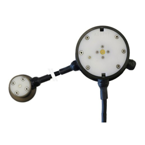
roadway. The passive measuring instrument IRS31Pro-UMB is used to determine the road surface
temperature, the height of the water film above the sensor and the saline concentration on the sensor
(from which the freezing temperature is derived). The built-in road condition models use these variables
to determine the corresponding road conditions.
The sensor provides the following established and commonly used decision-making data for winter
maintenance services: water film height, road condition, road surface temperature and freezing
temperature. In addition, the sensor delivers an ice percentage reading. As the ice percentage increases
on the surface, the friction coefficient falls and this can then be used to support preventive gritting
decisions.
Depending on the sensor type, up to 2 below-ground temperatures can be measured, preferably at
depths of 5 cm and 30 cm.
The equipment is connected by way of a 4-pin connection cable (with a length of 50 m or 100 m,
depending on the type).
The measured values can be requested over the RS485 interface in accordance with the UMB protocol.
During commissioning, configuration and verification takes place using the UMB Config Tool
(Windows®PC software).
4.1 IRS31Pro-UMB Sensor
Figure 1: Sensor
Below-ground
temperature 1
Depth 5 cm
Below-ground
temperature 2
Depth 30 cm
Conductivity
measurement
Temperature measurement
Water film height measurement

IRS31Pro-UMB Operating Manual V10 / 01.2020
G. Lufft Mess- und Regeltechnik GmbH 9
5 Generation of Measurements
It is recommended to query the average channels. The measured values of the TLS-channels are
based on the configured averaging.
5.1 Current Measurement (act)
The value of the last measurement is transmitted when the current measurement value is requested.
5.2 Average Value (avg)
The number of measurements that are included in the moving average can be configured between 1 and
20. In the factory setting, the sampling rate is 10 s and the moving average is generated from 6
measurements.
The "average" road condition is calculated from the average values of the underlying channels.
The average freezing temperature is calculated from the average saline concentration.
5.3 Sampling Rate
The sampling rate in the sensor is configurable and can be set at 10, 20, 30 or 60 seconds. Typically,
measurement values are polled at intervals of 1, 2, 5 or 10 minutes. An average value is recommended if
the measurement and sampling rates are different.
Figure 2: UMB Config Tool: Sensor Configuration / Sensor Settings Menu

IRS31Pro-UMB Operating Manual V10 / 01.2020
G. Lufft Mess- und Regeltechnik GmbH 10
6 Transmission of Measurements
The factory default setting for the transmission of measurements is UMB binary protocol.
You can find an example of a measurement request for the various protocols and a complete summary of
the list of channels (including TLS channels) in the Appendix.
6.1 Measurements
6.1.1 Data Types Used
uint8 unsigned char (8 bit unsigned integer)
uint16 unsigned short (16 bit unsigned integer)
float32 float (32 bit floating-point number according to IEEE-754)
6.1.2 Road Surface Temperature
Sampling rate: adjustable 10, 20, 30, 60s; see section 5.3 Sampling Rate, page 9
Units: normalized, °C; °F
Request channels:
UMB Channel Measuring Range
act min max avg Measured Value Data Type min max Unit
100 105 Road temperature uint16 0 65520 norm value
101 106 Road temperature float32 -40.0 80.0 °C
102 107 Road temperature float32 -40.0 176.0 °F
6.1.3 External Temperature 1 (5cm depth)
Sampling rate: see section 5.3
Units: normalized, °C; °F
Request channels:
UMB Channel Measuring Range
act min max avg Measured Value Data Type min max Unit
110 115 External temperature 1 uint16 0 65520 norm value
111 116 External temperature 1 float32 -40.0 80.0 °C
112 117 External temperature 1 float32 -40.0 176.0 °F
6.1.4 External Temperature 2 (30cm depth)
Sampling rate: see section 5.3
Units: normalized, °C; °F
Request channels:
UMB Channel Measuring Range
act min max avg Measured Value Data Type min max Unit
120 125 External temperature 2 uint16 0 65520 norm value
121 126 External temperature 2 float32 -40.0 80.0 °C
122 127 External temperature 2 float32 -40.0 176.0 °F
6.1.5 Freezing Temperature NaCl
Sampling rate: see section 5.3
Units: normalized, °C; °F
Request channels:
UMB Channel Measuring Range
act min max avg Measured Value Data Type min max Unit
150 155 Freezing temp. NaCl uint16 0 65520 norm value
151 156 Freezing temp. NaCl float32 -40.0 0.0 °C
152 157 Freezing temp. NaCl float32 -40.0 32.0 °F

IRS31Pro-UMB Operating Manual V10 / 01.2020
G. Lufft Mess- und Regeltechnik GmbH 11
6.1.6 Freezing Temperature MgCl21
Sampling rate: see section 5.3
Units: normalized, °C; °F
Request channels:
UMB Channel Measuring Range
act min max avg Measured Value Data Type min max Unit
170 175 Freezing temp. MgCl2 uint16 0 65520 norm value
171 176 Freezing temp. MgCl2 float32 -40.0 0.0 °C
172 177 Freezing temp. MgCl2 float32 -40.0 32.0 °F
6.1.7 Freezing Temperature CaCl21
Sampling rate: see section 5.3
Units: normalized, °C; °F
Request channels:
UMB Channel Measuring Range
act min max avg Measured Value Data Type min max Unit
190 195 Freezing temp. CaCl2 uint16 0 65520 norm value
191 196 Freezing temp. CaCl2 float32 -40.0 0.0 °C
192 197 Freezing temp. CaCl2 float32 -40.0 32.0 °F
6.1.8 Water Film Height
Sampling rate: see section 5.3
Units: normalized, µm; mil
Request channels:
UMB Channel Measuring Range
act min max avg Measured Value Data Type min max Unit
600 605 Water film height uint16 0 65520 norm value
601 606 Water film height float32 0.0 10000.0 µm
602 607 Water film height float32 0.0 393.70 mil
6.1.9 Saline Concentration NaCl
Sampling rate: see section 5.3
Units: normalized, % percentage by weight, g/m2, lbs. p. l. mile,
Request channels:
UMB Channel Measuring Range
act min max avg Measured Value Data Type min max Unit
800 805 Saline concent. NaCl uint16 0 65520 norm value
801 806 Saline concent. NaCl float32 0 100 %
910 915 Saline concent. NaCl float32 0 100 g/m2
920 925 Saline concent. NaCl float32 0 1280 lbs.p.l.mile
6.1.10 Ice Percentage
Sampling rate: see section 5.3
Units: %
Request channels:
UMB Channel Measuring Range
act min max avg Measured Value Data Type min max Unit
810 815 Ice percentage float32 0.0 100 %
6.1.11 Friction
Sampling rate: see section 5.3
1 experimental implementation

IRS31Pro-UMB Operating Manual V10 / 01.2020
G. Lufft Mess- und Regeltechnik GmbH 12
Units: none
Request channels:
UMB Channel Measuring Range
act min max avg Measured Value Data Type min max Unit
820 825 Friction float32 0.0 1.0
6.1.12 Saline Concentration MgCl2 2
Sampling rate: see section 5.3
Units: normalized, % percentage by weight, g/m2, lbs. p. l. mile
Request channels:
UMB Channel Measuring Range
act min max avg Measured Value Data Type min max Unit
830 835 Saline concent.MgCl2 uint16 0 65520 norm value
831 836 Saline concent.MgCl2 float32 0 100 %
911 916 Saline concent.MgCl2 float32 0 100 g/m2
921 926 Saline concent.MgCl2 float32 0 1280 lbs.p.l.mile
6.1.13 Saline Concentration CaCl2 2
Sampling rate: see section 5.3
Units: normalized, % percentage by weight, g/m2, lbs. p. l. mile
Request channels:
UMB Channel Measuring Range
act min max avg Measured Value Data Type min max Unit
840 845 Saline concent.CaCl2 uint16 0 65520 norm value
841 846 Saline concent.CaCl2 float32 0 100 %
912 917 Saline concent.CaCl2 float32 0 100 g/m2
922 927 Saline concent.CaCl2 float32 0 1280 lbs.p.l.mile
6.1.14 Road Condition
Sampling rate: see section 5.3
Units: logical coding
Request channels:
UMB-Chanel Measuring Range
act min max avg Measured Value Data Type min max Unit
900 905 Road condition uint8 0 99
Coding Meaning Description
10 Dry There is no liquid water on the road or the water film height is below the dry-
moist threshold.
15 Moist There is liquid water on the road and the water film height is between the dry-
moist and moist-wet thresholds.
20 Wet There is liquid water on the road; the water film height has raised above the
moist-wet threshold.
25 Moist with salt Describes a moist road condition where the freezing temperature is lower than -
0.1°C.
30 Wet with salt Describes a wet road condition where the freezing temperature is lower than -
0.1°C.
35 Ice There is frozen water on the road, mostly in the form of ice or snow.
40 Snow There is snow on the road
45 Frost There is frost on the road
The factory settings for the moist and wet thresholds are 10 and 200 µm, respectively. These settings can
be adjusted in the sensor configuration (see screenshot).
2 experimental implementation

IRS31Pro-UMB Operating Manual V10 / 01.2020
G. Lufft Mess- und Regeltechnik GmbH 13
Figure 3: Set Moist / Wet Thresholds
6.1.15 State of Coupling
Sampling rate: see section 5.3
Units: none
Request channels:
UMB Channel Measuring Range
act min max avg Measured Value Data Type min max Unit
950 State of coupling uint8 0 99
6.1.16 Measurement Counter
Sampling rate: see section 5.3
Units: none
Request channels:
UMB Channel Measuring Range
act min max avg Measured Value Data Type min max Unit
20001 Measurement counter uint16 0 65520
6.1.17 Resistance
Sampling rate: see section 5.3
Units: Ohm
Request channels:
UMB Channel Measuring Range
act min max avg Measured Value Data Type min max Unit
32210 resistive_avg float32 -1.0E15 1.0E15 ohm

IRS31Pro-UMB Operating Manual V10 / 01.2020
G. Lufft Mess- und Regeltechnik GmbH 14
7 Installation
The road sensor must be installed in the centre of the road lane. On two lane carriageways installation
takes place in the left-hand lane.
7.1 Preparation
A drill hole of diameter > 16 cm and depth 6 cm is required for inserting the sensor. For the connection
cable, a slot of width 2 cm and depth 5 cm is cut into the road surface.
Attention! Be careful not to damage the insulation layer when working on bridges. (In this case it
is not always possible to maintain a depth of 6 cm.)
For temperature sensor 1 (optional), a slot is required at an angle of approximately 68º in relation
to the connection cable slot. The slot is cut into the road with a width of 2 cm, depth of 5 cm and
length of 35 cm.
For temperature sensor 2 (optional), a drill hole is required with a depth of 30 cm and a diameter of 2 cm.
In relation to the connection cable slot, this must be positioned at an angle of approximately -68º,
approximately 20 cm from the outer rim of the road sensor drill hole (see Figures 2 and 3). A slot of width
2 cm must be cut between the two drill holes.
If necessary, the slot lengths must be adjusted in accordance with the installation conditions at the site.
For sensors with only one temperature sensor, temperature sensor 2 is omitted. In this case, temperature
sensor 1 can also be installed at a depth of 30 cm (see installation instructions for temperature sensor 2).
The external temperature sensors are protected to IP67. Constant use under water must be avoided.
One of the external temperature sensors is marked with a red cable flag, on which the intended
installation depth is given. If the sensor is not installed in the designated depth, the channel assignment
must be changed in the sensor configuration. See chapter 10.2.4 Device Settings.
7.2 Installation
Warning: The cable connections must not be opened under any circumstances!
Shortening the supply cable is only permitted at the cabinet end of the cable. The supply cable must be
placed in a protective tube that prevents any expansion of the road surface from being transmitted to the
cable. Be careful not to expose the cables of the road sensor to tensile stress during the installation.
Warning: Damage to the sheathing of the supply cable or external sensors will lead to the ingress
of water into the sensor! Sensors with damaged cables must not be installed and can only be
repaired by Lufft.
Insert the road sensor into the designated drill hole in such a way that it is flush with the road surface. In
order to achieve this, place the installation aid - which is already mounted on delivery - on the surface of
the road. If necessary, adjust the sensor position by bending the installation aid.
Under no circumstances must the road sensor project beyond the surface of the road (possible
damage due to snow-clearing vehicles!).
Fill the cavities with casting resin concrete.
Only such concrete casting systems may be used in which the temperature during the curing process
remains below 80°C (176ºF), as otherwise the road sensor will be damaged. After the concrete has
hardened, remove the installation aid and the green protective foil. Re-insert the fixing screws of the
installation aid into the open holes of the sensor. All 6 fastening screws of the cover are then tightened
with a torque of 2 Nm.

IRS31Pro-UMB Operating Manual V10 / 01.2020
G. Lufft Mess- und Regeltechnik GmbH 15
7.2.1 Extending the Supply Cable (e.g. 100 m)
Important: The original cable must be shortened after the shortest possible distance (curbside 5 m) and
extended from there. The loop impedance of the entire cable must not exceed 10 Ω.
Figure 4: Cable Extension
Example: Extension to 100 m with a 0.5 mm² cable with loop impedance of 73.2 Ω/km and parallel
connection of 4 wires in each case:
At 100 m the result per wire is a loop impedance of 7.3 Ω.
By connecting 4 wires in parallel the result is a loop impedance of 7.3 Ω / 4 = 1.83 Ω
Figure 5: Example of an Extension Box

IRS31Pro-UMB Operating Manual V10 / 01.2020
G. Lufft Mess- und Regeltechnik GmbH 16
7.2.1.1 Extension Table for IRS31Pro-UMB Passive Road Sensor
Total
Distance
RS485
Terminator
Required
IRS31Pro-
UMB
Original
Cable
Extension Cable
A-2ZF(L)2Z
Nx2x0.8
Wire
Range 0.5mm2 0.8mm2 Power Supply
Wire Bundle
Total Wire
Pairs
[m] max. [m] up to…[m] x times N
100 - 100 -- --
200 - 50 150 3x 4
300 - 50 250 4x 6
400 YES 50 350 6x 10
500 YES 50 450 7x 10
600 YES 50 550 9x 10
700 YES 50 650 10x 20
800 YES 50 750 11x 20
900 YES 50 850 13x 20
1000 YES 50 950 14x 20
1100 YES 50 1050 16x 20
1200 YES 50 1150 17x 20
Notes:
Recommended extension cable: A-2YF(L)2Y Nx2x0, 8 or similar;
Core pair 2x (2 times) means 2 pairs of wires, e.g. 2x2x0.8, because 2 individual wires are 1 pair for the
power supply (+ & -).
RS485 termination resistance required means that a resistance of 120 ohms should be connected parallel
to the RS485 2-wire interface, either on the sensor inlet or sleeve.
7.3 Connecting the Supply Cable
The road sensor supply cable is connected to the power supply and the bus system (e.g. ISOCON-UMB)
in the control panel.
The data lines and the supply voltage of each IRS31Pro-UMB must be electrically isolated from
each other. This can be achieved for example by means of a LUFFT ISOCON-UMB. If the sensor is
operated without electrical isolation, the sensor may be destroyed and the warranty expires!
The screening of the connecting cable MUST be laid to earth in the control panel! Under no
circumstances is it allowed to connect the negative supply voltage (GND1) with the cable shield
(connected to earth) of the sensor.
For Sensors with 12 VDC power supply the end of the cable in the cabinet is marked by the
manufacturer with a red heat shrink tubing!

IRS31Pro-UMB Operating Manual V10 / 01.2020
G. Lufft Mess- und Regeltechnik GmbH 17
Figure 6: Example of a Standard
Lufft UMB Control Cabinet
Figure 7: Examples of the Earthing of the Cable Screening
The sensors are delivered with two different cables: color coded or numerically coded.
Connection of the road sensor supply lead:
1 ............. white ................ negative power supply
2 ............. brown............... positive power supply
3 ............. green ............... RS485_A
4 ............. yellow .............. RS485_B
If colored cables are not used, the numbers apply.
Figure 8: ISOCON-UMB Connection
Note: When installing the system, please also pay attention to the operating instructions for the ISOCON-
UMB.
Attention: Errors in connection will destroy the road sensor!
Attention: A connection of the sensor to 24 VDC leads after a short time to the destruction of the
sensor.

IRS31Pro-UMB Operating Manual V10 / 01.2020
G. Lufft Mess- und Regeltechnik GmbH 18
7.3.1 Cable Connection for SDI12 Operation
There are two options to connect the sensor to a SDI12 logger:
Connecting the road sensor with power supply by the SDI12 bus
1 ............. white ................ SDI12 GND
2 ............. brown............... SDI12 +12V
3 ............. green ............... not connected
4 ............. yellow .............. SDI12 Signal
Attention: In this case SDI12 GND may not be connected to earth!
Connecting the sensor with isolated power supply:
1 ............. white ................ negative power supply
2 ............. brown............... positive power supply
3 ............. green ............... SDI12-GND
4 ............. yellow .............. SDI12 Signal
Attention: The power supply lines may not be connected to earth!

IRS31Pro-UMB Operating Manual V10 / 01.2020
G. Lufft Mess- und Regeltechnik GmbH 19
Figure 9: IRS31Pro-UMB Installation in the Road with 2 External Temperature Sensors

IRS31Pro-UMB Operating Manual V10 / 01.2020
G. Lufft Mess- und Regeltechnik GmbH 20
Figure 10: Installing the IRS31Pro-UMB
7.4 Use of Surge Protection (8379.USP)
When using surge protection (order no.: 8379.USP), please note the connection example in the operating
instructions for surge protection.
This manual suits for next models
12
Table of contents
Other Lufft Accessories manuals

Lufft
Lufft VS2k-UMB User manual

Lufft
Lufft NIRS31-UMB User manual

Lufft
Lufft 8810.U051 User manual

Lufft
Lufft MARWIS User manual

Lufft
Lufft VENTUS-USB User manual

Lufft
Lufft SHM 31 User manual

Lufft
Lufft ARS31-UMB User manual

Lufft
Lufft ARS31Pro-UMB User manual

Lufft
Lufft CHM 15k Nimbus User manual

Lufft
Lufft WS10 User manual