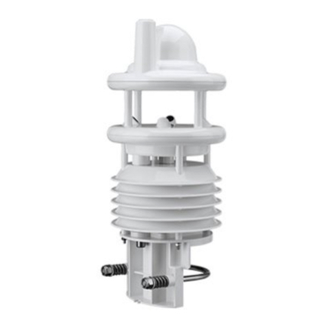
Lufft VENTUS-UMB User manual


Operating Manual V25/09.2019
Ventus / Ventus-X / V200A
2

Operating Manual V25/09.2019
Ventus / Ventus-X / V200A
Chapter Contents 3
Contents
Contents.......................................................................................................................................................3
1Please Read Before Use.......................................................................................................................5
1.1 Symbols Used................................................................................................................................5
1.2 Safety Instructions.........................................................................................................................5
1.3 Designated Use.............................................................................................................................5
1.4 Incorrect Use .................................................................................................................................5
1.5 Warranty........................................................................................................................................5
1.6 Brand Names.................................................................................................................................5
2Scope of Supply....................................................................................................................................6
3Order Number........................................................................................................................................6
4Accessories...........................................................................................................................................6
5Additional Documents and Software...................................................................................................6
6Equipment Description.........................................................................................................................7
6.1 Wind ..............................................................................................................................................7
6.2 Virtual Temperature.......................................................................................................................8
6.3 Air Pressure...................................................................................................................................8
6.4 Heating..........................................................................................................................................8
7Generation of Measurements.............................................................................................................10
7.1 Current Measurement (act)..........................................................................................................10
7.2 Minimum and Maximum Values (min and max)...........................................................................10
7.3 Average Value (avg)....................................................................................................................10
7.4 Vectorial Average Value (vct) ......................................................................................................10
8Measurement Output ..........................................................................................................................11
8.1 Virtual Air Temperature................................................................................................................11
8.2 Heating Temperature...................................................................................................................11
8.3 Air Pressure.................................................................................................................................11
8.4 Wind Speed.................................................................................................................................12
8.5 Wind Direction .............................................................................................................................12
8.6 Wind Measurement Quality .........................................................................................................13
8.7 Status Information........................................................................................................................13
9Installation...........................................................................................................................................14
9.1 Fastening.....................................................................................................................................14
9.2 North Alignment...........................................................................................................................15
9.3 Selecting the Installation Location ...............................................................................................16
10 Connections ........................................................................................................................................18
10.1 Supply Voltage.............................................................................................................................19
10.2 RS485 Interface...........................................................................................................................19
10.3 Analog Interface Circuits..............................................................................................................19
10.4 Control line...................................................................................................................................20
10.5 Connection to ISOCON-UMB (8160.UISO) .................................................................................20
10.6 Use of surge protector (8379.USP-V)..........................................................................................20
10.7 SDI12 Connection........................................................................................................................21
11 Commissioning ...................................................................................................................................22
12 Configuration and Test.......................................................................................................................22
12.1 Lufft ConfigTool ...........................................................................................................................22
12.2 Configuration ...............................................................................................................................22
12.3 Value retrieval..............................................................................................................................28
13 Firmware Update.................................................................................................................................31

14 Maintenance ........................................................................................................................................31

Operating Manual V25/09.2019
Ventus / Ventus-X / V200A
Chapter Contents 4
15 Technical Data.....................................................................................................................................32
15.1 Measuring Range / Accuracy.......................................................................................................33
15.2 Drawing .......................................................................................................................................34
16 EC Declaration of Conformity ............................................................................................................35
17 Fault Description.................................................................................................................................36
18 Disposal...............................................................................................................................................37
18.1 Within the EC...............................................................................................................................37
18.2 Outside the EC ............................................................................................................................37
19 Repair / Corrective Maintenance........................................................................................................37
19.1 Technical Support........................................................................................................................37
20 Appendix..............................................................................................................................................38
20.1 Channel List Summary ................................................................................................................38
20.2 Channel List Summary per TLS2002 FG3...................................................................................39
20.3 Communication in Binary Protocol...............................................................................................40
20.4 Communication in ASCII Protocol................................................................................................43
20.5 Communication in NMEA Protocol...............................................................................................45
20.6 Communication in SDI-12 Mode..................................................................................................55
20.7 Communication in Modbus Mode ................................................................................................66
21 List of Figures .....................................................................................................................................74
22 Keyword Index.....................................................................................................................................75

Operating Manual V25/09.2019
Ventus / Ventus-X / V200A
Chapter 1 Please Read Before Use 5
1 Please Read Before Use
1.1 Symbols Used
Important information concerning potential hazards to the user
Important information concerning the correct operation of the equipment
1.2 Safety Instructions
Installation and commissioning must be carried out by suitably qualified specialist
personnel only.
Never take measurements on or touch live electrical parts.
Pay attention to the technical data and storage and operating conditions.
1.3 Designated Use
The equipment must only be operated within the range of the specified technical
data.
The equipment must only be used under the conditions and for the purposes for
which it was designed.
The safety and operation of the equipment can no longer be guaranteed if it is
modified or adapted.
1.4 Incorrect Use
If the equipment is installed incorrectly
It may not function.
It may be permanently damaged.
Danger of injury may exist if the equipment is allowed to fall.
If the equipment is not connected correctly
It may not function.
It may be permanently damaged.
The possibility of an electrical shock may exist.
1.5 Warranty
The warranty period is 12 months from the date of delivery. The warranty is forfeited if the
designated use is violated.
1.6 Brand Names
All brand names referred to are subject without limitation to the valid trademark and ownership
rights of the respective owner.

Operating Manual V25/09.2019
Ventus / Ventus-X / V200A
Chapter 2 Scope of Supply 6
2 Scope of Supply
Equipment
Connection Plan
3 Order Number
8371.UMT
Ventus
-UMB (metal)
8371.UMTX
Ventus-X
-UMB(metal
8371.UA01
V200A
-UMB (plastics)
Wind direction
Wind speed
Virtual temperature
4 Accessories
ISOCON-UMB
8160.UISO
Surge protection
8379.USP-V
Power supply unit
Recommended power supply unit:
Phoenix contact
2866323 TRIO-PS/1AC/24DC/10
Connector
8371.UST1 or
Amphenol C091 31D008 101 2
Connector cable
Recommended cable:
8371.UK015 15m
8371.UK050 50m
5 Additional Documents and Software
You can download the following documents and software via the Internet at www.lufft.com.
Operating Manual
This document
UMB-Config-Tool
Windows®software for testing, firmware updates and
configuration of UMB devices
UMB Protocol
Communication protocol for UMB devices
Firmware
The current device firmware

Operating Manual V25/09.2019
Ventus / Ventus-X / V200A
Chapter 6 Equipment Description 7
6 Equipment Description
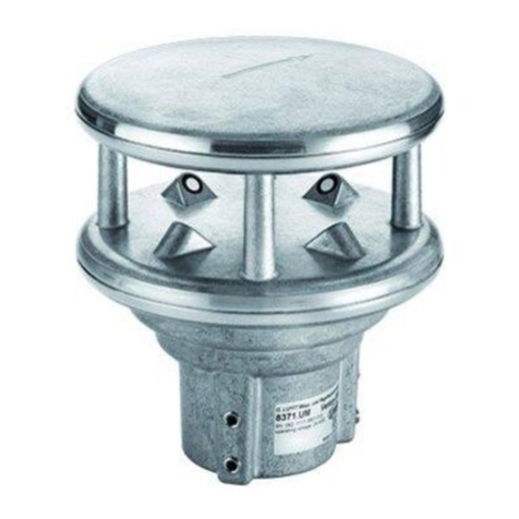
Ventus
is a seawater-resistant wind meter which in addition to determining wind direction and
wind speed is also capable of calculating virtual temperature.
Ventus-X
is a
Ventus
variant. Beneath the standard heating,
Ventus-X
has got an additional heating,
which is built within the ultrasonic heads. Therefore it particularly is suitable for winter operation.
V200A
is a
Ventus
with a plastic housing. So it is a low-cost alternative to the conventional
Ventus
.
The equipment is connected by way of an 8 pole screw connector.
The measured values can be requested over a variety of interfaces:
- RS485 interface in half or full duplex
oUMB binary protocol
oUMB ASCII protocol
oNMEA protocol
oSDI-12 protocol
oModbus-RTU and Modbus-ASCII protocols
- Analog data output of 2 adjustable channels with 4-20 mA, 0 –10V or (channel 1 only)
as frequency 2 –2000Hz
During commissioning, configuration and measurement polling takes place using the UMB-
Config-Tool (Windows®PC software).
6.1 Wind
The measurement principle implemented for the
Ventus
-UMB is based on the measurement of
the time of flight of ultrasonic pulses in air.
The measurement setup includes two measurement sections, arranged at an angle of 90°, with
two ultrasonic transceivers each. The measurement sections are activated in turn and the time
of flight of the ultrasonic pulses between the respective transmitter and receiver is measured.
Within one measurement cycle each of the ultrasonic heads will work once as transmitter and
once as receiver.
When measuring in still air all times of flight of one cycle will be equal on average.
If however an air flow is passing through the sensor, the ultrasonic pulse packet moving in the
direction of the air flow will be accelerated, while the packet moving in opposite direction to the
air flow will be decelerated. That means, the time of flight in the direction of wind will be shorter,
while that in direction opposite to the wind direction will be longer.
Figure 1: Measurement Sections

Operating Manual V25/09.2019
Ventus / Ventus-X / V200A
Chapter 6 Equipment Description 8
The orthogonal arrangement of the measurement sections allows to evaluate the x and y
components (resp. North-south and east-west components) of the air flow.
Basically the sonic velocity, and with it the time of flight of the ultrasonic pulse packets, will be
influenced by air temperature and air humidity. The alternating measurement (north->south /
south->north, west->east / east->west) compensates this influence.
The differences of the time of flight are averaged over a number of measurements, then the
wind speed and wind direction is evaluated from the average.
The design of the sensor head protects, to a large extend, the measurement sections against
rain and snow. The heating of the sensor prevents icing of the ultrasonic transceivers.
The aerodynamic design of the sensor head minimizes influences on the wind flow. Remaining
deviations are evaluated during device calibration so that they are compensated during the
calculation of wind speed and wind direction.
6.2 Virtual Temperature
Due to the physical relationship between the velocity of propagation of sound and the air
temperature, the approximate ambient temperature can be determined with the aid of
ultrasound sensors.
6.3 Air Pressure
The air pressure is measured by an integrated air pressure sensor
6.3.1 Air Density
Air density is calculated from the measured air pressure, virtual temperature and relative
humidity. The
Ventus
doesn‘t measure relative humidity so a constant value, which can be
adjusted through ConfigTool.NET, is applied. Factory setting is 75%.
6.4 Heating
For winter operation
Ventus
has got 2 heating elements (one element only on plastic version) to
keep the sensor free of snow and ice. One element is in the cover (metal version only) and the
other is built into the ultrasonic sensors.
To reduce the maximum operating current of the device, upper and lower heating can be
switched alternatingly.
Separate measurement channels are available for the surveillance of the temperatures of upper
and lower heater.
By default the heating is set in automatic mode and full capacity. This is the recommended
heating mode of the sensor.
Figure 2 Influence of Wind on Time of Flight

Operating Manual V25/09.2019
Ventus / Ventus-X / V200A
Chapter 6 Equipment Description 9
6.4.1 Heating mode
The heating of the device can be operated in 4 different modes:
off: Heating always off
auto: Automatic heating control1
The heating switches on when the housing temperature falls below +15°C
(adjustable between 2°C and 20°C) and switches off at a housing temperature of
>+20°C (set temperature +5°C) (metal)
The heating switches on when the housing temperature falls below +50°C
(adjustable between 2°C and 70°C) and switches off at a housing temperature of
>+55°C (set temperature +5°C) (plastics)
testmode: The switch-on temperature is adjusted to +40°C; in this condition the heating
switches on at room temperature (for test purposes only)
ctrl high: Heating control is disabled when the control line is at the “high” level, else
automatic
ctrl low: Heating control is disabled when the control line is at the “low” level, else automatic
For configuration of the heating mode see chapter 12.
6.4.2 Heating capacity
The heating capacity can be set in accordance with the following modes:
full: Full heating capacity (ca. 240W)1
alternating: Alternating heating:
Cover plate alternating to base plate (ca. 100W or 150W alternating)
The next level of heating switches in if the pre-set temperature for the
respective level is not reached within 4 minutes.
In this mode you only need a power supply with 140W.
For configuration of the heating capacity see chapter 12.
6.4.3 Heater Turn Off on Over / Under Voltage
If the heater turn off on over / under voltage is activated, the heating will be automatically
switched off, if the supply voltage is outside of the surveillance window.
The lower threshold is ~20V, the upper threshold is ~28V.
For configuration of the turn-off-function see chapter 12.
1Factory setting

Operating Manual V25/09.2019
Ventus / Ventus-X / V200A
Chapter 7 Generation of Measurements 10
7 Generation of Measurements
7.1 Current Measurement (act)
In accordance with the specified sampling rate, the value of the last measurement is transmitted
when the current measurement value is requested. Each measurement is stored in a circular
buffer for the subsequent calculation of minimum, maximum and average values.
7.2 Minimum and Maximum Values (min and max)
When requesting the minimum and maximum values, the corresponding value is calculated - via
the circular buffer at the interval specified in the configuration (1- 60 measurements) - and
transmitted.
Note: In the case of wind direction, the minimum / maximum value indicates the direction at
which the minimum / maximum wind speed was measured.
7.3 Average Value (avg)
When requesting the average value, this is calculated - via the circular buffer at the interval
specified in the configuration (1 - 60 measurements) - and transmitted. In this way moving
averages can also be calculated.
7.4 Vectorial Average Value (vct)
In the specific case of wind measurement, measurements are calculated vectorially. To this
end, the average values of the vectors are generated internally. Hence the value (wind speed)
and angle (wind direction) of the vector are calculated.
Note: On delivery, the interval for the calculation of minimum, maximum and average values is
set at 60 measurements. If necessary, this can be adjusted to the particular requirements with
the aid of the UMB-Config-Tool (see page 28).

Operating Manual V25/09.2019
Ventus / Ventus-X / V200A
Chapter 8 Measurement Output 11
8 Measurement Output
The factory default setting for the transmission of measurements is UMB binary protocol.
You can find an example of a measurement request for the various protocols and a complete
summary of the list of channels in the Appendix.
8.1 Virtual Air Temperature
Sampling rate 1 –10 seconds
Generation of average value 1 –60 measurements
Units °C; °F
Request channels:
UMB Channel
Measuring Range
act
min
max
avg
Measurement Variable
min
max
unit
100
120
140
160
Virtual air temperature
-50.0
70.0
°C
105
125
145
165
Virtual air temperature
-58.0
158.0
°F
Note: In order to transmit the current measurement value the second measurement values are
averaged over the sampling rate.
8.2 Heating Temperature
Sampling rate 1 –10 seconds
Generation of average value 1 –60 measurements
Units °C; °F
Request channels:
UMB Channel
Measuring Range
act
min
max
avg
Measurement Variable
min
max
unit
112
Heating temperature top
-50.0
150.0
°C
113
Heating temperature bottom
-50.0
150.0
°C
117
Heating temperature top
-58.0
302.0
°F
118
Heating temperature bottom
-58.0
302.0
°F
8.3 Air Pressure
Sampling rate 10 seconds
Generation of average value 20 measurements
Units hPa
Request channels:
UMB Channel
Measuring Range
act
min
max
avg
Measurement Variable
min
max
unit
300
320
340
360
Absolute air pressure
300.0
1200.0
hPa
305
325
345
365
Relative air pressure
300.0
1200.0
hPa
Note: For pressure measurement a hardware version equal or greater than 3.0 and a software
version equal or greater than 1.6 is necessary!
8.3.1 Air Density
Sampling rate 10 seconds
Unit kg/m³
Request channell:
UMB Channel
Measuring Range
act
min
max
avg
Measurement Variable
min
max
Unit
310
Air Density
0.0
3.0
kg/m³
Note: Relative humidity is required for the calculation of air density. As Ventus-UMB does not
include a humidity sensor, an adjustable standard value is applied. With UMB-ConfigTool.NET
this value can be adapted to the conditions at the location of installation (see Chapter 12.2.8) .
Factory setting is 75% rel. humidity.

Operating Manual V25/09.2019
Ventus / Ventus-X / V200A
Chapter 8 Measurement Output 12
8.4 Wind Speed
Sampling rate 250ms; 1 –10 seconds
Generation of average value 1 –60 measurements
Generation of maximum value 1 –60 measurements based on the internal second
measurement values
Units m/s; km/h; mph; kts
Response threshold 0.1 m/s (metal) or 0.3 m/s (plastics)
Request channels:
UMB Channel
Measuring Range
act
min
max
avg
vct
Measurement Variable
min
max
unit
400
420
440
460
480
Wind Speed
0
90.0
m/s
405
425
445
465
485
Wind Speed
0
324.0
km/h
410
430
450
470
490
Wind Speed
0
201.3
mph
415
435
455
475
495
Wind Speed
0
174.9
kts
Note: In order to transmit the current measurement value the second measurement values are
averaged over the sampling rate.
8.4.1 Wind Gust Speed (WMO Specification)
Sampling Rate 250ms
Generation of Value Highest 3sec average of the last 10min
Request channels:
UMB Channel
Measuring Range
act
min
max
avg
vct
Measurement Variable
min
max
unit
443
Wind Gust Speed
0
90.0
m/s
448
Wind Gust Speed
0
324.0
km/h
453
Wind Gust Speed
0
201.3
mph
458
Wind Gust Speed
0
174.9
kts
Note: With extended sampling rates (50ms / 100ms) the evaluation of wind gust is deactivated.
The channels will show status “channel off” (0x36)
8.5 Wind Direction
Sampling rate 250ms; 1 –10 seconds
Generation of average value 1 –60 measurements
Generation of maximum value 1 –60 measurements based on the internal second
measurement values Unit °
Response threshold 0.1 m/s (metal) or 0.3 m/s (plastics)
Request channels:
UMB Channel
Measuring Range
act
min
max
avg
vct
Measurement Variable
min
max
unit
500
520
540
580
Wind Direction
0
359.9
°
543
Wind Gust Direction
0
359.9
°
Note: In order to transmit the current measurement value the second measurement values are
averaged over the sampling rate.
The minimum / maximum wind direction indicates the direction at which the minimum /
maximum wind speed was measured.
The wind gust direction is the vector average of the direction measured during the highest 3sec
speed average of the last 10min.

Operating Manual V25/09.2019
Ventus / Ventus-X / V200A
Chapter 8 Measurement Output 13
8.6 Wind Measurement Quality
Sampling rate 250ms; 1 –10 seconds
Units %
Request channels:
UMB Channel
Measuring Range
act
min
max
avg
vct
Measurement Variable
min
max
unit
805
Wind measurement quality
0
100
%
Note: The value is updated every 0.25 –10 seconds and transmits the minimum wind quality of
the last measurement.
This value allows the user to assess how well the measurement system is functioning in the
respective ambient conditions. In normal circumstances the value is 90 - 100%. Values up to
50% do not represent a general problem. If the value falls towards zero the measuring system is
reaching its limits.
If during critical ambient conditions the system is no longer able to conduct reliable
measurements, error value 55h (85d) is transmitted for wind speed and wind direction (device
unable to execute valid measurement due to ambient conditions).
8.7 Status Information
UMB Channel
Measuring Range
act
min
max
avg
vct
Measurement Variable
4006
Status supply voltage, upper
threshold (~ 28V)
0 : Voltage <= 28V
1: Voltage > 28V
4007
Status supply voltage, lower
threshold (~ 20V)
0 : Voltage >= 20V
1: Voltage < 20V
4997
Status lower heating
0: Heating off
1: Heating on
4998
Status upper heating
0: Heating off
1: Heating on

Operating Manual V25/09.2019
Ventus / Ventus-X / V200A
Chapter 9 Installation 14
9 Installation
The sensor bracket is designed to be installed on the top of a mast with a diameter of 50mm or
2”.
The following tools are required for the installation:
Hexagon socket 4.0
Compass for aligning
Ventus
to the North
9.1 Fastening
Figure 3 Fastening to the Mast
Loosen nuts
Push the sensor onto the top of the mast from above
Align the sensor to the North
Tighten both nuts evenly and secure with locking varnish
Mast tube
Nuts

Operating Manual V25/09.2019
Ventus / Ventus-X / V200A
Chapter 9 Installation 15
9.2 North Alignment
In order for the wind direction to display correctly, the sensor must be aligned to the North. The
sensor has a number of directional arrows and a North drill hole for this purpose.
Figure 4 North Markings
Procedure:
If the sensor is already installed, first loosen both nuts evenly until you can turn the sensor
easily
Using the compass, identify the North and fix a point of reference on the horizon
Position the sensor in such a way that the South and North sensors are in alignment with the
fixed point of reference in the North
Tighten both nuts evenly
Figure 5 Alignment to North
poor
good
Note: As the magnetic North Pole indicated by the compass differs from the Geographic North
Pole, account must be taken of the declination (variation) at the location when aligning the
sensor.
Depending on the location, the variation can be more than 15° (in North America for example).
In Central Europe the variation can be largely ignored at present (< 3°). You can find further
helpful information on this subject on the Internet.
Point of reference in the North

Operating Manual V25/09.2019
Ventus / Ventus-X / V200A
Chapter 9 Installation 16
9.3 Selecting the Installation Location
In order to guarantee long service life and correct equipment operation, please pay attention to
the following points when selecting the installation location.
9.3.1 General Instructions
Stable subsurface for installing the mast
Free access to the equipment for maintenance works
Reliable power supply for permanent operation
Good network coverage when transmitting over a mobile communications network
Note: The computed measurements specifically apply to the equipment location only. No
conclusions can be drawn with regard to the wider environment or a complete road section.
ATTENTION:
Only approved and tested appliances (conductors, risers etc.) should be used to install
the device on the mast.
All relevant regulations for working at this height must be observed.
The mast must be sized and anchored appropriately.
The mast must be earthed in accordance with regulations.
The corresponding safety regulations for working at road side and in the vicinity of the
road carriageway must be observed.
If the equipment is installed incorrectly
It may not function.
It may be permanently damaged.
Danger of injury may exist if the equipment is allowed to fall.
9.3.2 Installation of Ventus
Installation at the top of the mast
Installation height at least 2m above the ground
Free field around the sensor
Note: Buildings, bridges, embankments and trees may corrupt the wind measurement. Equally,
passing traffic may cause gusts which may influence the wind measurement.

Operating Manual V25/09.2019
Ventus / Ventus-X / V200A
Chapter 9 Installation 17
9.3.3 Installation Sketch
Road carriageway
min. 10 m
min. 2 m
Ventus
Mast
min. 10 m
Tree, bush
etc.
Figure 6 Installations Sketch

Operating Manual V25/09.2019
Ventus / Ventus-X / V200A
Chapter 10 Connections 18
10 Connections
There is an 8 pole screw connector on the underside of the equipment. This serves to connect
the supply voltage and interfaces by a connection cable.
Equipment connector:
Figure 7 Connections
Pin assignment full duplex:
1 Y Serial interface RXD- pink
2 B Serial interface TXD- yellow
3 Control connection red
4 Z Serial interface RXD+ grey
5 A Serial interface TXD+ green
6 Analog ground blue
7 Supply voltage - white
8 Supply voltage + brown
Pin assignment half duplex/analog interface:
1 Analog interface A pink
2 B Serial interface RXD/TXD- yellow
3 Control connection red
4 Analog interface B grey
5 A Serial interface RXD/TXD+ green
6 Analog ground blue
7 Supply voltage - white
8 Supply voltage + brown
Pin assignment SDI-12 interface:
1 - pink
2 SDI-12 Data yellow
3 SDI-12 activation red
4 - grey
5 green
6 SDI-12 GND and SDI-12 activation blue
7 Supply voltage - white
8 Supply voltage + brown
View on cable socket solder
connection
3
1
5
2
8
4
7
6

Operating Manual V25/09.2019
Ventus / Ventus-X / V200A
Chapter 10 Connections 19
(for SDI12 connection please always follow the detailed notes in Chap. 10.7)
The connection cable screen must NOT be laid to ground in the control panel for
Ventus
!
The
Ventus
will be earthed through the screws with the earthed mast .
The connection cable screen MUST be laid to ground in the control panel for V200A !
If the equipment is not connected correctly
- It may not function
- It may be permanently damaged
- The possibility of an electrical shock may exist under certain circumstances
10.1 Supply Voltage
The supply voltage for
Ventus
is 24V DC ± 10%. The power supply unit used must be approved
for operation with equipment of protection class III (SELV).
10.2 RS485 Interface
The equipment has an electrically isolated RS485 interface for configuration, measurement
polling and the firmware update.
The RS485 interface is designed as optionally half or full duplex, 2 or 4 wire connection.
The following operating restrictions exist depending on the half or full duplex operation setting:
Full duplex
Half duplex1
Autonomous telegram transmission is
possible
No autonomous telegram transmission
possible
Transmission of values via current output is
not possible
Transmission of values via current output is
possible
Heating control via control pin is possible
Triggering of NMEA telegram transmission
over Control-PIN is possible
Triggering of NMEA telegram transmission
over Control-PIN is not possible
SDI-12 Mode not possible
SDI-12 Mode possible
Firmware update not possible
Firmware update possible
Restrictions in full and half duplex operation
See page 32 for technical details.
10.3 Analog Interface Circuits
2 analog interface circuits are provided for analog data transmission. Both are updated every
250ms.
Interface A can be configured for 0 or 4-20mA current output, 0 or 2-10V voltage output as well
as for frequency output in the range from 2 –2000Hz (with adjustable voltage level up to 10V)
Note: For the use of the analog outputs the serial communication protocol must be set to UMB
binary!
Interface B can be configured for 0 or 4-20mA current output and 0 or 2-10V voltage output
The channels to be transmitted by way of these interfaces can be adjusted with the aid of the
UMB-Config-Tool. The default values are Channels 400 (current wind speed in m/s (A)) and 500
(current wind direction (B)).
The scaling of the outputs is also adjustable.
The maximum load on the current output is 300 .
1Factory setting

Operating Manual V25/09.2019
Ventus / Ventus-X / V200A
Chapter 10 Connections 20
10.4 Control line
The respective function can be adjusted using the UMB-Config-Tool. The control line can be
used either to control heating in half or full duplex operation or to control telegram transmission
in full duplex mode. In this case control is possible by means of a volt-free switching contact.
Control line at “high” when control and analog ground are not connected.
Control line at “low” when control and analog ground are short-circuited.
For activation of the SDI-12 mode the control line is to be set to “low”, i.e. control input and
analog ground are to be connected.
10.4.1 Control line disabled
The control line level has no effect.
10.4.2 Heating control
-Heating is disabled when control line is at “high” level, otherwise automatic
-Heating is disabled when control line is at “low” level, otherwise automatic
10.4.3 Control of telegram transmission in NMEA protocol
-Telegram transmission triggered on rising edge of control voltage
-Telegram transmission triggered on falling edge of control voltage
-Telegram transmission while control voltage is “high”
-Telegram transmission while control voltage is “low”
10.5 Connection to ISOCON-UMB (8160.UISO)
Warning: The power supply is not connected to the ISOCON-UMB but is wired directly to the
power supply unit, as the ISOCON-UMB is not designed for the 240W heating duty of the
Ventus
device.
Please pay attention to the ISOCON-UMB operating manual when building the equipment.
10.6 Use of surge protector (8379.USP-V)
Please refer to the connection example in the operating manual when using the surge protector
(Order no.: 8379.USP).
Green: RS485
interface A
Yellow: RS485
interface B
Figure 8 Connection to ISOCON-UMB
This manual suits for next models
5
Table of contents
Other Lufft Accessories manuals

Lufft
Lufft VS2k-UMB User manual

Lufft
Lufft CHM 15k Nimbus User manual

Lufft
Lufft NIRS31-UMB User manual

Lufft
Lufft SHM 31 User manual

Lufft
Lufft ARS31Pro-UMB User manual

Lufft
Lufft MARWIS User manual

Lufft
Lufft VENTUS-USB User manual

Lufft
Lufft WS800-UBM User manual

Lufft
Lufft WS10 User manual

Lufft
Lufft 8810.U051 User manual