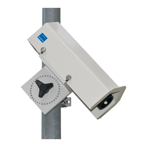
Lufft NIRS31-UMB User manual


© G. Lufft Mess- und Regeltechnik GmbH, Fellbach, Germany. Subject to change without notice.
48.7230-NIRS31E
Document version V8.2 (03/2017)

Operating Manual V8.2/03.2017 Non Invasive Road Sensor
G. Lufft Mess- und Regeltechnik GmbH, Fellbach, Germany 3
Contents
1Please Read Before Use.............................................................................................................................................5
1.1 Symbols Used .....................................................................................................................................................5
1.2 Safety Instructions...............................................................................................................................................5
1.3 Designated Use...................................................................................................................................................5
1.4 Incorrect Use.......................................................................................................................................................5
1.5 Guarantee............................................................................................................................................................5
1.6 Brand Names.......................................................................................................................................................5
2Scope of Delivery........................................................................................................................................................6
3Order Numbers............................................................................................................................................................7
3.1 Accessories.........................................................................................................................................................7
3.2 Spare Parts..........................................................................................................................................................7
3.3 Additional Documents and Software....................................................................................................................7
4Equipment Description...............................................................................................................................................8
4.1 Road Surface Temperature.................................................................................................................................8
4.2 Water Film Height................................................................................................................................................8
4.3 Ice Layer Thickness.............................................................................................................................................8
4.4 Road Condition....................................................................................................................................................8
4.5 Ice Percentage ....................................................................................................................................................8
4.6 Freezing Temperature.........................................................................................................................................8
4.7 Saline Concentration ...........................................................................................................................................9
4.8 Snow Height ........................................................................................................................................................9
4.9 Friction.................................................................................................................................................................9
4.10 Sensor Technology NIRS31-UMB.....................................................................................................................10
5Generation of Measurements...................................................................................................................................11
5.1 Current Measurement (act)................................................................................................................................11
6Operation Modes.......................................................................................................................................................11
6.1 Normal Operation..............................................................................................................................................11
6.2 Energy Saving Mode .........................................................................................................................................11
7Measurement Output ................................................................................................................................................12
7.1 Measurements...................................................................................................................................................12
7.2 Additional Sensor Information............................................................................................................................15
8Installation.................................................................................................................................................................17
8.1 Fastening...........................................................................................................................................................17
8.2 Aligning the Sensor............................................................................................................................................18
8.3 Selecting the Installation Location .....................................................................................................................19
9Connections ..............................................................................................................................................................22
9.1 Equipment Connector........................................................................................................................................22
9.2 Pin Assignment..................................................................................................................................................22
9.3 Supply Voltage ..................................................................................................................................................22
9.4 RS485 Interface.................................................................................................................................................22
9.5 Connection to ISOCON-UMB (8160.UISO).......................................................................................................23
9.6 Use of Surge Protection (8379.USP).................................................................................................................23
10 Commissioning.........................................................................................................................................................24
10.1 Conditions for the Initial Commissioning............................................................................................................24
10.2 Important Instructions for Commissioning..........................................................................................................24
11 Sensor Adjustment...................................................................................................................................................25
11.1 Readjustment using the UMB Config Tool.........................................................................................................25
11.2 Adjustment during Operation.............................................................................................................................25
12 Configuration and Testing........................................................................................................................................26
12.1 Factory Settings.................................................................................................................................................26
12.2 Configuration with the UMB Config Tool............................................................................................................26

Operating Manual V8.2/03.2017 Non Invasive Road Sensor
4G. Lufft Mess- und Regeltechnik GmbH, Fellbach, Germany
12.3 Function Test with the UMB Config Tool........................................................................................................... 28
13 Firmware Update...................................................................................................................................................... 29
14 Maintenance.............................................................................................................................................................. 30
14.1 Replacing the Reflector Unit ............................................................................................................................. 30
14.2 Cleaning the Transmitter and Receiver Plates.................................................................................................. 31
14.3 Resetting the Service Level.............................................................................................................................. 32
14.4 Function Test.................................................................................................................................................... 32
14.5 Checking the Sensor Adjustment...................................................................................................................... 33
14.6 Generate Status File......................................................................................................................................... 33
15 Technical Data.......................................................................................................................................................... 34
15.1 Measurement Range / Accuracy....................................................................................................................... 35
15.2 Drawings........................................................................................................................................................... 36
16 Fault Description...................................................................................................................................................... 37
17 Disposal .................................................................................................................................................................... 38
17.1 Within the EC.................................................................................................................................................... 38
17.2 Outside the EC ................................................................................................................................................. 38
18 Repair / Corrective Maintenance............................................................................................................................. 38
18.1 Technical Support............................................................................................................................................. 38
19 Appendix................................................................................................................................................................... 39
19.1 Channel List Summary...................................................................................................................................... 39
19.2 Channel List Summary per TLS2002 FG3........................................................................................................ 40
19.3 Communication in Binary Protocol.................................................................................................................... 41
19.4 Communication in ASCII Protocol..................................................................................................................... 44
19.5 Communication in SDI-12 Mode....................................................................................................................... 46
20 List of Figures........................................................................................................................................................... 56
21 Index.......................................................................................................................................................................... 57

Operating Manual V8.2/03.2017 Non Invasive Road Sensor
G. Lufft Mess- und Regeltechnik GmbH, Fellbach, Germany 5
1 Please Read Before Use
Please read this Operating Manual carefully and keep it handy for future reference. Please
note that various components of the sensor and the described software may look somewhat
different from those shown in the illustrations in this operating manual.
This manual is valid for devices of the Lufft NIRS31-UMB with device version 21 or
higher (03/2013). Some functions or features specified in this manual may not be
available or may not be valid with older device versions. The device version is indicated
as the last number of the serial number printed on the type plate, e.g.: the device with
SN: 063.1010.0707.014 has the device version 14.
1.1 Symbols Used
Important information concerning potential hazards to the user
Important information concerning the correct operation of the equipment
1.2 Safety Instructions
Installation and commissioning must only be carried out by suitably qualified specialist
personnel.
Never take measurements on or touch live electrical parts.
Pay attention to the technical data and storage and operating conditions.
1.3 Designated Use
The equipment must only be operated within the range of the specified technical data.
The equipment must only be used under the conditions and for the purposes for which it
was designed.
The safety and operation of the equipment can no longer be guaranteed if it is modified or
adapted.
1.4 Incorrect Use
If the equipment is not correctly installed:
It may not function or its operation may be limited.
It may be permanently damaged.
Danger of injury may exist if the equipment is allowed to fall.
If the equipment is not correctly connected:
It may not function.
It may be permanently damaged.
The possibility of an electrical shock may exist under certain circumstances.
1.5 Guarantee
The guarantee period is 24 months from the date of delivery. The guarantee is forfeited if the
designated use is violated.
1.6 Brand Names
All brand names referred to are subject without limitation to the valid trademark and
ownership rights of the respective owner.

Operating Manual V8.2/03.2017 Non Invasive Road Sensor
6G. Lufft Mess- und Regeltechnik GmbH, Fellbach, Germany
2 Scope of Delivery
The content of the delivery consists of the following components:
Sensor NIRS31-UMB
Mast clamp
Sounding pipe
Operating manual
Transport packaging
Note: The delivery does not include a connection cable; this must be ordered to the
required length (15 or 50 meters; see Accessories page 7).
Note: The sensor must always be transported in the original packaging, as otherwise it will
be damaged.

Operating Manual V8.2/03.2017 Non Invasive Road Sensor
G. Lufft Mess- und Regeltechnik GmbH, Fellbach, Germany 7
3 Order Numbers
NIRS31-UMB 8710.UT01
Non-invasive road sensor including integrated road surface temperature sensor
3.1 Accessories
15m connection cable including
connector
8371.UK015
50 m connection cable including
connector
8371.UK050
Power supply unit 24V/100VA
8366.USV1
ISOCON-UMB
8160.UISO
Surge protection
8379.USP
3.2 Spare Parts
Reflector unit
8710.ULAMP
3.3 Additional Documents and Software
You can download the following documents and software via the Internet at www.lufft.com.
Operating Manual
This document
UMB Config Tool
Windows®software for testing, firmware updates and
configuration of UMB devices
UMB Protocol
Communication protocol for UMB devices
Firmware
The current equipment firmware

Operating Manual V8.2/03.2017 Non Invasive Road Sensor
8G. Lufft Mess- und Regeltechnik GmbH, Fellbach, Germany
4 Equipment Description
Depending on the requirements of the road traffic meteorological monitoring network,
sensors are installed in the roadways and / or "overhead". The Lufft NIRS31-UMB completes
the product range to include a non-invasive, intelligent sensor. The NIRS31-UMB provides
an alternative to the Lufft IRS31-UMB, especially for measuring points such as bridges,
which do not always allow direct installation of sensors in the roadway. In addition, at points
where asphalt repairs often take place, it is no longer necessary to remove the sensor
technology during repair works. The optical measuring device NIRS31-UMB for the detection
of water, ice and snow can be mounted on a bridge or mast. The measurement distance
between the measuring device and the road surface can be from 6 to 15 meters.
The sensor delivers established and commonly used decision-making data to winter
maintenance services, including water film height, road condition, road surface temperature
and freezing temperature. In addition, the sensor provides ice percentage and snow depth
readings. As the ice percentage on the road surface increases, the friction coefficient falls off
and this can be used as a guide in preventive road gritting decision-making.
In contrast to built-in road sensors, non-invasive sensors are not able to measure
underground soil temperature.
The equipment is connected by way of an 8 pole plug-in terminal and associated connection
cable (available in lengths of 15m and 50m).
The measured values can be requested over the RS485 interface in accordance with the
UMB protocol.
During commissioning, configuration and measurement polling takes place using the UMB
Config Tool (Windows®PC software).
4.1 Road Surface Temperature
Road surface temperature is measured by means of a non-invasive pyrometer, which is fully
integrated into the sensor.
4.2 Water Film Height
Measurement of the water film height on the road surface takes place by means of non-
invasive optical spectroscopy. The water film height is the proportion of liquid water.
4.3 Ice Layer Thickness
Measurement of the ice layer thickness on the road surface takes place by means of non-
invasive optical spectroscopy.
The ice layer thickness indicates the proportion of the frozen water as water
equivalent. The sum of water film height and ice layer thickness results the total water
equivalent.
4.4 Road Condition
The current road condition is determined from the measurement of water film height and
road surface temperature. The sensor calculates the following conditions: dry, damp, wet,
snow / ice and critical wetness.
4.5 Ice Percentage
The proportions of frozen solution are determined from the measurement data provided by
optical spectroscopy and transmitted as the ice percentage.
4.6 Freezing Temperature
The freezing temperature is determined on the basis of the current road surface temperature
and the measured ice percentages.
Note: The freezing temperature can only be determined if ice percentages have already
formed. Determination of freezing temperature is currently limited to the de-icing agent
sodium chloride (NaCl).

Operating Manual V8.2/03.2017 Non Invasive Road Sensor
G. Lufft Mess- und Regeltechnik GmbH, Fellbach, Germany 9
4.7 Saline Concentration
The saline concentration is calculated from the current freezing temperature.
Note: The saline concentration can only be determined if ice percentages have already
formed. Determination of saline concentration is currently limited to the de-icing agent
sodium chloride (NaCl).
4.8 Snow Height
The sensor detects the snow height in the field of measurement.
Note: the snow height is an additional information and it is not part of the water equivalent.
4.9 Friction
Friction describes the grip of tires on the road surface. This can be reduced as a result of
environmental influences such as rain or snow. The value of the friction is scaled between
0.1 and 1.0. High values indicate a good grip, and low values indicate a bad grip. The
highest value is reached in dry road conditions. If there is water on ice the lowest value is the
result.

Operating Manual V8.2/03.2017 Non Invasive Road Sensor
10 G. Lufft Mess- und Regeltechnik GmbH, Fellbach, Germany
Fig. 1: Sensor
Technology
4.10 Sensor Technology NIRS31-UMB
Receiver
Pyrometer
Reflector unit
Sounding pipe

Operating Manual V8.2/03.2017 Non Invasive Road Sensor
G. Lufft Mess- und Regeltechnik GmbH, Fellbach, Germany 11
5 Generation of Measurements
5.1 Current Measurement (act)
The value of the last measurement is transmitted when the current measurement value is
requested.
6 Operation Modes
The sensor can be operated in two different modes.
6.1 Normal Operation
Provided that the power supply is not limited, this mode is recommended because it is not
restricted.
In normal operation, the sensor continually measures and provides continuously updated
measurement values.
6.2 Energy Saving Mode
If the power supply is limited, it is possible to operate the sensor in energy saving mode. In
this mode the sensor samples only one time per minute. Between the measurements, the
sensor is switched to a standby mode. Thereby the power consumption is reduced on
average to lower than 35%.
6.2.1 Restrictions in Energy Saving Mode
Note: Setting the sensor to energy saving mode has the following restrictions:
The sampling and data update rate is fixed at 1 minute.
The first 3 minutes after starting the device and during the measurement, the NIRS31-
UMB is running at full capacity, therefore, the supply has to be designed for full power.
The response time may be delayed.
In case of rapid changes of the road conditions (e.g. onset of rainfall) it is used to
measured more often to reduce the response time; thereby, the power consumption may
increase slightly.
In case of heavy traffic load, it is used to measured more often for a proper function of the
noise suppression; this maybe increase the power consumption
Very high traffic load can cause interference of the measurement.
Due to the low power, the sensor can freeze rather

Operating Manual V8.2/03.2017 Non Invasive Road Sensor
12 G. Lufft Mess- und Regeltechnik GmbH, Fellbach, Germany
7 Measurement Output
The factory default setting for the transmission of measurements is UMB binary protocol.
You can find an example of a measurement request for the various protocols and a complete
summary of the list of channels in the Appendix.
7.1 Measurements
7.1.1 Road Surface Temperature
Sampling rate 1 minute
Units °C; °F
Request channels:
UMB Channel
Measuring Range
act
min
max
avg
Measurement Variable (float32)
min
max
unit
100
Road surface temperature
-40.0
70.0
°C
101
Road surface temperature
-40.0
158.0
°F
7.1.2 Freezing Temperature
Sampling rate <1 minute
Units °C; °F
Request channels:
UMB Channel
Measuring Range
act
min
max
avg
Measurement Variable (float32)
min
max
unit
110
Freezing temperature NaCl
-40.0
0.0
°C
111
Freezing temperature NaCl
-40.0
32.0
°F
7.1.3 Water Film Height
Sampling rate <1 minute
Units µm; mil
Request channels:
UMB Channel
Measuring Range
act
min
max
avg
Measurement Variable (float32)
min
max
unit
600
Water film height
0.0
2000.0
µm
605
Water film height
0.0
78.7
mil
7.1.4 Ice Layer Thickness
Sampling rate <1 minute
Units µm; mil
Request channels:
UMB Channel
Measuring Range
act
min
max
avg
Measurement Variable (float32)
min
max
unit
601
Ice layer thickness
0.0
2000.0
µm
606
Ice layer thickness
0.0
78.7
mil
The indication of ice layer thickness corresponds to the water equivalent.

Operating Manual V8.2/03.2017 Non Invasive Road Sensor
G. Lufft Mess- und Regeltechnik GmbH, Fellbach, Germany 13
7.1.5 Road Condition
Sampling rate <1 minute
Units logic coding
Request channels:
UMB Channel
Coding
act
Measurement Variable (uint8)
900
Road condition
0 Dry
1 Damp
2 Wet
3 Ice
4 Snow / ice
5 Chemically wet
6 Critically wet
8 Snow
99 Undefined
dry: on the road there is no liquid water, the water film height is less than
the damp threshold
damp: on the road there is liquid water; the water film height is less than the
wet threshold
wet: on the road there is liquid water; water film height is equal or greater
than the wet threshold
snow / ice: frozen water is on the road; it’s in the form of snow or ice;a
differentiation is not possible.
snow: frozen water is on the road; it’s mostly in the form of snow
ice: frozen water is on the road; it’s mostly in the form of ice
chemically wet: water film height is equal to or greater than the damp threshold and
the road temperature is below 1.5 °C, the formation of ice is
prevented by using de-icing chemicals.
critically wet: water film height is equal to or greater than the damp threshold and
the road temperature is below 1.5 °C, the formation of ice particles
has already begun.
The thresholds for damp and wet in the factory settings are 30 and 100µm, they can be
adjusted in the sensor configuration.

Operating Manual V8.2/03.2017 Non Invasive Road Sensor
14 G. Lufft Mess- und Regeltechnik GmbH, Fellbach, Germany
7.1.6 Ice Percentage
Sampling rate <1 minute
Units %
Request channels:
UMB Channel
Measuring Range
act
min
max
avg
Measurement Variable (float32)
min
max
unit
800
Ice percentage
0.0
100.0
%
7.1.7 Saline Concentration
Sampling rate <1 minute
Units %
Request channels:
UMB Channel
Measuring Range
act
min
max
avg
Measurement Variable (float32)
min
max
unit
810
Saline concentration NaCl
0.0
100.0
%
7.1.8 Snow Height
Sampling rate <1 minute
Units mm
Request channels:
UMB Channel
Measuring Range
act
min
max
avg
Measurement Variable (float32)
min
max
unit
610
Snow height
0.0
10.0
mm
7.1.9 Friction
Sampling rate <1 minute
Units none
Request channels:
UMB Channel
Measuring Range
act
min
max
avg
Measurement Variable (float32)
min
max
unit
820
Friction
0.0
1.0
none

Operating Manual V8.2/03.2017 Non Invasive Road Sensor
G. Lufft Mess- und Regeltechnik GmbH, Fellbach, Germany 15
7.2 Additional Sensor Information
The sensor delivers further information about the condition and operation of the sensor.
7.2.1 Service Level
UMB Channel
Measuring Range
act
Measurement Variable (sint16)
min
max
unit
4000
Service level
100
%
100% Equipment recently serviced
< 12% Service due in less than 90 days
< 4% Service due in less than 30 days
A negative value indicates that the due service period has been exceeded.
7.2.2 Remaining Time to Next Service
UMB Channel
Measuring Range
act
Measurement Variable (sint16)
min
max
unit
4001
Remaining time to next service
17520
h
Indicates the number of hours to the next service.
A negative value indicates that the due service period has been exceeded.
7.2.3 Lamp Status
UMB Channel
act
Measurement Variable (uint8)
4002
Lamp status
0 Lamp OK
1 Lamp faulty
Note: In the event of a faulty lamp it is necessary to change the reflector unit to restore
correct operation.
7.2.1 Measure Status
UMB Channel
act
Measurement Variable (uint8)
4003
Measure Status
Bit 0
Status Transmitter
0 transmitter is working properly
1 transmitter is not working properly; in case of permanent state,
please contact hotline
Bit 1
Status Receiver
0 receiver is working properly
1 receiver is not working properly; in case of permanent state,
please contact hotline
Bit 2
Status Temperature
0 measurement is working properly
1 interference suppression of implausible temperature values is
active; for example, it can be caused by a stationary vehicle
under the sensor; after this failure the sensor is working properly
again
Bit 3
Status Pyrometer
0 measurement is working properly
1 interference suppression of implausible pyrometer values is
active; for example, it can be caused by a stationary vehicle
under the sensor; after this failure the sensor is working properly
again
Bit 4
Status Signal
0 measurement is working properly
1 interference suppression of implausible signals is active; for
example, it can be caused by a stationary vehicle under the
sensor; after this failure the sensor is working properly again

Operating Manual V8.2/03.2017 Non Invasive Road Sensor
16 G. Lufft Mess- und Regeltechnik GmbH, Fellbach, Germany
7.2.2 Energy consumption ratio
UMB Channel
Measuring Range
act
Measurement Variable (float32)
min
max
unit
4004
energy consumption ratio
0.0
100.0
%
In normal operation mode, the energy consumption ratio and thus the energy consumption is
always 100%, because the sensor is in continuous operation. In energy save mode, the
value is the energy consumption ratio of the last hour.

Operating Manual V8.2/03.2017 Non Invasive Road Sensor
G. Lufft Mess- und Regeltechnik GmbH, Fellbach, Germany 17
Fig. 2: Mast Bracket
Fig. 3: Sensor
Attachment
8 Installation
The sensor bracket is designed for installation on a mast with a diameter of 60 –76mm.
The following tools are required for the installation:
2 open-end or box wrenches, SW17
8.1 Fastening
Attach the bracket to the mast at the prescribed height using the bolts, nuts and washers
provided. Hold the nut firmly with one wrench and tighten the bolts evenly and securely with
the second wrench.
Note: Select the correct bolts in accordance with the diameter of the mast:
60 –69 mm mast diameter: 100 mm long bolts
70 –76 mm mast diameter: 120 mm long bolts
Attach the sensor to the bracket from above and fasten using the bolts and washers
provided. Tighten the bolts but make sure that the sensor can still be moved.
Washer
Bolt
Nut
Bolt
Washer

Operating Manual V8.2/03.2017 Non Invasive Road Sensor
18 G. Lufft Mess- und Regeltechnik GmbH, Fellbach, Germany
Fig. 4: Aligning the
Sensor
8.2 Aligning the Sensor
A look through the small tube (sounding pipe) on the bottom of the sensor indicates the
center of the measurement field on the road surface. Align the sensor with the center of the
roadway while retaining the angle of measurement (between 45 and 85°) and firmly tighten
the bolts.
Note: If you wish to attach the sensor to the opposite side of the mast, you can adjust the
bracket on the sensor prior to installation. To do this, remove the 4 bolts marked *1, rotate
the bracket by 180° and reattach with the 4 bolts.
Nut with washer
Sounding pipe
*1
*1

Operating Manual V8.2/03.2017 Non Invasive Road Sensor
G. Lufft Mess- und Regeltechnik GmbH, Fellbach, Germany 19
Fig. 5: Roadway
Condition
8.3 Selecting the Installation Location
In order to guarantee long service life and correct equipment operation, please pay attention
to the following points when selecting the installation location.
8.3.1 General Instructions
Stable subsurface for installing the mast
Free access to the equipment for maintenance works
Reliable power supply for permanent operation
Good network coverage when transmitting over a mobile communications network
Note: The computed measurements specifically apply to the equipment location only. No
conclusions can be drawn with regard to the wider environment or a complete road section.
ATTENTION:
Only approved and tested appliances (conductors, risers etc.) should be used to install the
device on the mast.
All relevant regulations for working at this height must be observed.
The mast must be sized and anchored appropriately.
The mast must be grounded in accordance with regulations.
The corresponding safety regulations for working at road side and in the vicinity of the
roadway must be observed.
Special safety precautions are required when working on roadways in use.
If the equipment is not correctly installed:
It may not function.
It may be permanently damaged.
Danger of injury may exist if the equipment is allowed to fall.
8.3.2 Roadway Condition
The measurement surface of the roadway should be as even, flat and level as possible.
Important note: The measurement surface of the roadway must be free of disturbances and
flaws, e.g. road markings, manhole covers, potholes or cracks.
X
X
X

Operating Manual V8.2/03.2017 Non Invasive Road Sensor
20 G. Lufft Mess- und Regeltechnik GmbH, Fellbach, Germany
Fig. 6: Installation
Sketch Mast
8.3.3 Installation Sketch Mast
Measurement distance c: 6 to 15m
Measurement angle α: between 45 and 85°
Measurement surface diameter d = measurement distance c / 10
Table of contents
Other Lufft Accessories manuals

Lufft
Lufft SHM 31 User manual

Lufft
Lufft IRS31Pro-UMB User manual

Lufft
Lufft WS Series User manual

Lufft
Lufft CHM 15k Nimbus User manual

Lufft
Lufft VENTUS-USB User manual

Lufft
Lufft MARWIS User manual

Lufft
Lufft 8810.U051 User manual

Lufft
Lufft VENTUS-UMB User manual

Lufft
Lufft SHM 31 User manual

Lufft
Lufft ARS31Pro-UMB User manual
Popular Accessories manuals by other brands

Delta-T
Delta-T UV3pA user manual

PCB Piezotronics
PCB Piezotronics ICP 137B22A Installation and operating manual

Samsung
Samsung XE800ZAA user manual

Denon
Denon DN-HC4500 - DJ Mixer USB Controller operating instructions

Honeywell
Honeywell T7147 Product data

PCB Piezotronics
PCB Piezotronics IMI Sensors M080A132 Installation and operating manual