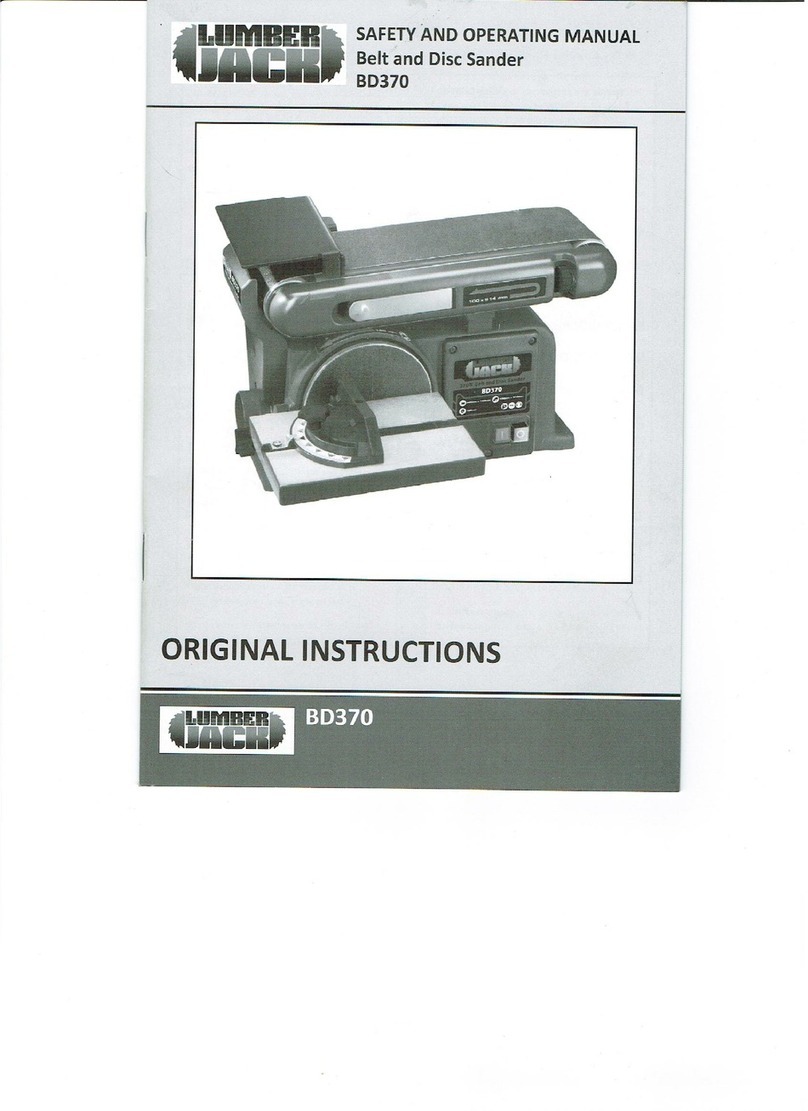
Lumberjack BD370 Installation manual

inci SAFETY AND OPERATING MANUAL
JACK Belt and Disc Sander
BD370
ORIGINAL INSTRUCTIONS
(i BD370
sa
raat te
All manuals and user guides at all-guides.com
all-guides.com

TABLE OF CONTENTS
Welcome to Lumberjack!
Dear customer, Congratulations on your purchase. Before using the
productfor the first time please be sure to read these instructions for use.
They provide you withall information necessary for using the productsafely and to
ensure its long service life.
Closely observe all safety information in these instructions!
General Power Tool Safety WarningS........sscscssesessssesseee
sessssseeeeee OL
Symbols & Cable Rating Chart .............. sesaveodoel de4siadvanecsesscdesesaccenseessesess OD
Machine Details and Product Features......csessesessessesseseesees srseseeneeensO6
ASSOMDIY......scecsssecceeseeeeeserseecesatesees
snes eeuasesineacoas senccscesetesesnctatt +08
Operation, Maintenance and Service.......ccsccsssssssscsseeeceeeees piciesvavscea bly
Lumberjack Guarantee......... svvosev ess csaibedsenuasseisecesotstesees ove eosesesesusnsesss essa lal
Declaration of Conformity.. enecersens desasaiss soatnceniene 16
Parts List... cesses eveneenseneerescesessscoscescascoscensonsosees «17
Parts Diagrarm.....ssscssssssssssessscssseecsescseecseseecsees
avosesessiged tsbattiesestest saonsases 19
eee Cicae
All manuals and user guides at all-guides.com

GENERAL POWER TOOL SAFETY WARNINGS
WARNING Read all safety warnings and
all instructions. Failure to follow the warnings
and instructions may result in electric shock, fire
and/or serious injury.
Save all warnings and instructions for
future reference. The term "powertool" in
the warnings refers to your electric (corded)
power tool or battery-operated (cordless) power
tool.
1. Work area safety
a) Keep work area clean and well lit. Cluttered
or dark areas invite accidents.
b) Do not operate power tools in explosive
atmospheres, such asin the presence of
flammable liquids, gases or dust. Power tools
create sparks which may ignite the dust or
fumes.
c) Keep children and bystanders away while
operating apower tool. Distractions can cause
you to lose control.
2. Electrical safety
a) Power tool plugs must match the outlet.
Never modify theplug in any way. Do not use
any adapter plugs with grounded power tools.
Unmodified plugs and matching outlets will
reduce risk of electric shock.
b) Avoid body contact with grounded surfaces,
such as pipes, radiators, ranges and
refrigerators. There is an increased risk of
electric shock if your body is grounded.
c) Do not expose power tools to rain or wet
conditions. Water entering apower tool will
increase the risk of electric shock.
d) Do not abuse the cord. Never use the cord for
carrying, pulling or unplugging the power tool.
Keep cord away from heat, oil, sharp edges or
moving parts. Damaged or entangled cords
increase the risk of electric shock.
e) When operating apower tool outdoors, use an
extension cord suitable for outdoor use. Use of a
cord suitable for outdoor use reduces therisk of
electric shock.
f) If operating apower tool in adamp location is
unavoidable, use aresidual current device (RCD)
protected supply. Use of an RCD reduces the risk
of electric shock.
3. Personal safety
a) Stay alert, watch what you are doing and use
common sense when operating a power tool. Do
not use a power tool while you are tired or under
the influence of drugs, alcohol or medication. A
moment of inattention while operating power
tools may result in serious personal injury.
b) Use personal protective equipment. Always
wear eye protection. Protective equipment such
as dust mask, non-skid safety shoes, hard hat, or
hearing protection used for appropriate conditions
will reduce personal injuries.
c) Prevent unintentional starting. Ensure the
switch is in the off position before connecting to
power source and/or battery pack, picking up or
carrying thetool. Carrying power tools with your
finger on the switch or energising power tools that
have the switch oninvites accidents.
d) Remove any adjusting key or wrench before
turning the power tool on. Awrench or akey
left
attached to arotating part of the power tool may
result in personal injury.

All manuals and user guides at all-guides.com

GENERAL POWER TOOL SAFETY WARNINGS
e) Do not overreach. Keep proper footing and
balance at all times. This enables better control
of the power tool in unexpected situations.
f) Dress properly. Do not wear loose clothing or
jewellery. Keep your hair, clothing and gloves
away from moving parts. Loose clothes,
jewellery or long hair can be caught in moving
parts.
g) If devices are provided for the connection of
dust extraction and collection facilities, ensure
these are connected and properly used. Use of
dust collection can reduce dust-related hazards.
4, Power tool use and care
a) Do not force the power tool. Use the correct
power tool for your application. The correct
power tool will do the job better and safer at the
rate for which it was designed.
b) Do not use the power tool if the switch does
not turn it on and off. Any power tool that
cannot be controlled with the switch is
dangerous and must be
repaired.
c) Disconnect the plug from the power source
and/or the battery pack from the power tool
before making any adjustments, changing
accessories, or storing power tools. Such
preventive safety measures reduce the risk of
starting the power tool accidentally.
d) Store idle power tools out of the reach of
children and do
not allow persons unfamiliar
with the power tool or these instructions to
operate the power tool. Power tools are
dangerous in the hands of untrained users.
e) Maintain power tools. Check for misalignment
or binding of moving parts, breakageof parts and
any other condition that may affect the power
tool’s operation. If damaged, have the power tool
repaired before use. Many accidents are caused
by poorly maintained power tools.
f) Keep cutting tools sharp and clean. Properly
maintained cutting tools with sharp cutting edges
are less likely to bind and are easier to control.
g) Use the power tool, accessories and tool bits
etc. in accordance with these instructions, taking
into account the working conditions and the work
to be performed. Use of the power tool for
operations different from those intended could
result in ahazardous situation.
5. Service
a) Have your power tool serviced by aqualified
repair person using only identical replacement
parts. This will ensure that the safety of the power
tool is maintained.
b) If the replacement of the supply cord is
necessary, this has to be done by the
manufacturer or its agent in order to avoid a
safety hazard.
6. Additional Safety and Working
Instructions
a) Dusts from materials such as lead-containing
coatings, some wood types, minerals and metals
can be harmful to one’s health and cause allergic
reactions, leading to respiratory infections and/or
cancer. Materials containing asbestos may only be
worked by specialists. Observe the relevant
regulations in your country for the materials to be
worked.
BD370 LUMBER
oii
All manuals and user guides at all-guides.com

TETeBap Tm,
—
GENERAL POWERTOOL SAFETY WARNINGS
b) Prevent dust accumulation at the workplace, j) Use clampsor a vice to hold work when |
Dusts can easily ignite. practical,
k) To minimize risk of tipping machine, always
7Additional Warnings for BELT /DISC
.
support long workpiece,
SANDER
!) Never sand more than one workpiece at atime.
Do
not stack more than one workpiece on the
machine base at atime.
a) Do not operate the tool until it is completely
assembled and installed according to the
instructions.
m) Do
not sand with the workpiece unsupported.
Do
not sand pieces of material that are too small
to be safely supported.
b) Provide adequate general or localized
lighting.
¢) Before work, check that the machine is
placed on an even surface with sufficient
stability. For your own safety, always mount
the machine to awork bench using bolts.
n) Avoid awkward operations and handpositions
where asudden slip could cause your hand to
move into the sanding belt or disc.
©)Avoid kickback by sanding in accordance with
d) Keep the surrounding area of the machine directional arrows.
well maintained and free of loose materials, :
such as chipsand cut-offs. p) Always maintain aclearance of 1.6 mm
between the work table and the machine.
e) Make sure the sanding belt is installed in the
correct direction. See directional arrow on back q) Never stand or have any part of your body in
ofbelt. line with the path of the workpiece,
f) Always havethe tracking adjusted properly ') Machine should never be connected to power
So the belt does not run off the pulleys. supply when you are assembling parts, making
adjustments, or when not in use.
8) Do not use sanding belts or padsthat are
damaged, torn, or loose. Use only correct si..e s)Neverleave tool running unattended. Do not
sanding belt and pad. leave tool until it comes to acomplete stop.
h) Always sand on the downward side of the t) If the power supply cord is damaged or
sanding disc when using the disc sander. otherwise defective, it must only be replaced by
|Sanding on the upward side of the disc can the manufacturer or by an authorized repair
cause the workpieceto fly out of Position, agent.
u) We recommend the use of aresidual current
i) Never perform layout, assembly or set-up device with aresidual current rating of 30mA or
work onthe table while the sander is operating. less,
|resulting in injury.
LUMBER |1:]2.¥/0)
iti
All manuals and user guides at all-guides.com

GENERAL POWER TOOLSAFETY WARNINGS
8. RESIDUAL RISKS
Even when the product is used as prescribed, it
is still impossible to completely eliminate
certain residual risk factors. The following
hazards may arise and the operator should pay
special attention to avoid the following:
a) Risk of contact with sanding belt or disc.
b) Burn hazard from contact with hot belt or
disc or work piece.
c) Damage torespiratory system if effective
dust mask is not worn.
d) Damageto hearing if effective hearing
protection is not worn.
9. Using an Extension Cable.
a) If an extension cable is required, use an
approved triple core extension cable suitable
for the power input of the tool.
b) Grounded tools always require athree wire
extension cable.
c) As the distance from the supply outlet
increases you must use aheavier gauge
extension cable. Using extension cables with
inadequately sized wire causes a serious drop in
voltage, resulting in loss of power and possible
tool damage.
d) The smaller the gauge number of the wire
the greater the capacity of the cord.
f) When using acable reel, always unwind the
cable completely.
BD370 (nnee
All manuals and user guides at all-guides.com
all-guides.com

SYMBOLS AND POWER RATING CHART
-Ri i
Danger!ead the operating Caution! Wear safety goggles.|instructions to reduce therisk of
||injury. |
nate |
|Caution! Wear ear defenders. The Caution! Risk
Of Injury! Do
impact of noise can cause damage |
not reach into the running
to hearing. saw blade.
a" ee
|@|Caution! Wear adust mask.
|
||Amperes |7.5M 15M 25M 30M 45M |60M |
||||
|0-2.0 666666
}|
|
4
2.1-3.4 6666|6|6|
||
Ie ||||||
3.5-5.0 6666|10 15 |
|51-71 |10 10 qo |10 Ce
||
_|
7.1-12.0 |15 15 15 |15 20 |20 |
12.1-20.0 |20 20, 720 |200050 35 -
||
||||
isch (ea
All manuals and user guides at all-guides.com

MACHINE DETAILS AND PRODUCT FEATURES
Machine
Details
Specifications:
Mains Voltage -230V /50Hz
Power Consumption- 370W
Belt Size -100mm x914mm
Belt Speed -7.5 m/s
Belt Tilt -0° -90°
Disc Size -0150mm
Disc Speed -225mm x158mm
Table Tilt -0° -45°
Gross Weight-19.5kg
Nett Weight-18.5kg
Intended Use
This power tool is intended to sand wood
only. Any other use is considered as not
intended use and any damagesor injuries
result from this unintended use is at
operators own risk.
This item is also not intended to be used
for continuous production or production
line use.
Package Contents:
Belt &Disc sander
All manuals and user guides at all-guides.com

PRODUCTFEATURES &ASSEMBLY INSTRUCTIONS
Product Features
1. Sanding stopper
Sanding belt
Tracking control knob
Belt tension lever
Sanding pad
ON/OFF Switch
Bevel scale
Dust port
Table bevel angle adjustment knob
.Mitre angle adjustment knob
.Mitre scale
.Mitre guide
.Work table
SMP
NAAR
WN
BREE
WnNneEOo
Assembly
Avoid unintentional starting of the machine.
During assembly and for all work on the machine,
the power plug must not be connected to the
mains supply.
Carefully remove all parts included in the delivery
from their packaging.
Remove all packaging material from the machine
and the accessories provided.
Before starting the operation of the machine for
thefirst time, check if all Parts listed in the box
content section have been supplied
Note: Check the power tool for possible damage.
Before further use of the machine, check that all
protective devices are fully functional. Anylightly
damaged parts must be carefully checked to
ensure flawless operation of the tool. All parts
must be properly mounted and all conditions
fulfilled that ensure faultless operation.
Damaged protective devices and parts must be
immediately replaced by an authorised service
centre,
qeee BD3
All manuals and user guides at all-guides.com

ASSEMBLY INSTRUCTIONS &OPERATION
Installing
Sanding Disc
Fix to Mounting
Board
(not supplied)
Clamp Mounting
Board to Work
Surface
(not supplied)
Readyfor Use
Operation
Adjusting Work Table
All manuals and user guides at all-guides.com

OPERATION
Sanding using
Mitre Gauge
cncw a
All manuals and user guides at all-guides.com
all-guides.com

OPERATION
Surface Sanding
Sanding inside
Curves
a
All manuals and user guides at all-guides.com

OPERATION/ MAINTENANCE AND
SERVICE
|Maintenance and Cleaning
Before any work on the dust collector itself, pull
the mains plug.
Vertical
Sanding
For safe and proper working,always keep the
dust collector and ventilation slots clean.
If the replacement of the supply cord is necessary,
this has to be done by an authorized service agent
in order to avoid asafety hazard.
If the belt and disc sander should fail despite the
care taken in manufacturing and testing procedures,
repair should be carried out by an authorised
service centre,
Do not modify the product in any way or use
accessories not approved by the manufacturer.
Your safety and that of others may be
compromised.
Do
not use the product if any switches, guards or
other functions does not work as intended. Return
to an authorised service centre for professional
repair or adjustment.
Do not make any adjustments whilst the product is
running.
Always make sure the power plug has been
removed from the mains power source before
making adjustments, lubricating or when doing
any maintenance on the product.
Before and after each use, check the product for
damageor broken parts. Keepthe product in top
|working condition by immediately replacing parts
with spares approved by the manufacturer.
Clean out accumulated dust using abrush or
vacuum cleaner, Do not use compressed air.
;BD370
All manuals and user guides at all-guides.com

OPERATION
To assure safety and reliability, all repairs,
including changing brushes, should be
performed. by an authorised service centre.
If the power supply cord is damaged, it must be
replaced only by the manufacturer or by an
authorised service centre to prevent damage to
the saw or risk of electrocution.
Changing Sanding
All manuals and user guides at all-guides.com

OPERATION
All manuals and user guides at all-guides.com

LUMBERJACK GUARANTEE
1. Guarantee
1.1 Lumberjack guarantees that for aperiod of
12 months from thedate of purchase the
components of qualifying products (see clauses
1.2.1 to 1.2.8) will be free from defects caused
by faulty construction or manufacture.
1.2. During this period Lumberjack,will repair or
replace free of charge any parts which are
proved to be faulty in accordance with
paragraph 1.1 providing that:
1.2.1 Youfollow the claims procedure set out in
clause 2
1.2.2 Lumberjack and its authorised dealers are
given reasonable opportunity after receiving
notice of the claim to examine the product
1.2.3 If asked to do so by Lumberjackor its
Authorised dealer, you return the product at
your own cost to Lumberjack’s or supplying
Authorised Dealer’s premises, for the
examination to take place clearly stating the
Returns Material Authorisation number given by
Lumberjack or an Authorised Dealer.
1.2.4 The fault in question is not caused by
industrial use, accidental damage, fair wear and
tear, wilful damage, neglect, incorrect electrical
connection, misuse, or alteration or repair of the
product without approval.
1.2.5 The product has been used in adomestic
environment only
1.2.6 The fault does not relate to consumable
items such as blades, bearings, drive belts, or
other wearing parts which can reasonably be
expected to wear at different rates depending
on usage.
1.2.7 The product has not been used for hire
purposes.
1.2.8 The product has been purchased by you as
the guarantee is not transferable from aprivate
sale.
2. Claims Procedure
2.1 In the first instance please contact the
Authorised Dealer who supplied the product to
you. In our experience many initial problems with
machines that are thought to be faulty due to
faulty parts are actually solved by correct setting
up or adjustment of the machine. Agood
Authorised Dealer should beable to resolve the
majority of these issues much more quickly than
processing aclaim under the guarantee. Ifa
return is requested by the Authorised Dealer or
Lumberjack, youwill be provided with aReturns
Material Authorisation number which must be
clearly stated on the returned package, and any
accompanying correspondence. Failure to provide
aReturns Material Authorisation number may
result in item being refused delivery at Authorised
Dealer.
2.2 Any issues with the product resulting in a
potential claim under the guarantee must be
reported to the Authorised Dealer from which it
was purchased within 48 hours of Receipt.
2.3 If the Authorised Dealer who supplied the
product to you has been unable to satisfy your
query, any claims made under this Guarantee
should be made directly to Lumberjack. The Claim
itself should be made in
a
letter setting out the
date and place of purchase, giving abrief
explanation of the problem which has led to the
claim. This letter should be then sent with proof
All manuals and user guides at all-guides.com
all-guides.com

LUMBERJACK GUARANTEE
of purchase to Lumberjack. If you include a
contact number with this it will speed your claim
up.
2.4 Please note that it is essential that the letter
of claim reaches Lumberjack on the last day of
this Guarantee at the latest. Late claims will not
be considered.
3. Limitation ofLiability
3.1 Weonly supply products for domestic and
Private use. You agree not to use the product for
any commercial, business or resale Purposes and
we have no liability to youfor any loss of profit,
loss of business, business interruption or loss of
business opportunity.
3.2 This Guarantee does not confer any rights
other than these expressly set out above and
does not cover any claims for consequential loss
or damage.This Guarantee is offered as an extra
benefit and does not affect your statutory rights
as aconsumer.
4. Notice
This Guarantee appliesto all product purchased
from an Authorised Dealer of Lumberjack within
the United Kingdom. Terms of Guarantee may
vary in other countries,
All manuals and user guides at all-guides.com

CE DECLARATION OF CONFORMITY
TOOLSAVE
Unit C, Manders Ind. Est.,
Old Heath Road, Wolverhampton,
|WV1 2RP.
Tel: 01902 450 470
Declares that the Belt & Disc Sander(BD370)
Is in compliance with the regulations included in the Directives:2006/42/EC
EC DECLARATION OF CONFORMITY
Certificate for EC-type examination delivered by Intertek Testing Services Ltd., Shanghai, Buildin,
No.86,1198 Qinzhou Road(North), Caohejing Development Zone,Shanghai 200233,China. (Verificati
No.:V131101555SHA-V1)
Person who declares: Bill Evans
01.09.2017
TheDirector
All manuals and user guides at all-guides.com

|27 58
|
Belt Tracking knob |
|28
|Capacitor 57 |Rubber washer i
|29 |Capacitor support I|58 |Tracking spring
Parts List
|No. |Description No |Description ||
|7
T
|1|Phillips screw +flat washer |30 |Phillips screw (white) |
|2|Base plate |31 Hex headbolt +BigFlat Washer(Black) |
|| 3
|Phillips Screw +spring washer +flat |32 Big flat washer(black) I
iwasher Assembly ||}
|4|Toothed lock washer |33 Work table support |
/5 Self tapping screw (Black) |34 Mitre gauge handle ||
|6Disc cover 35 |Work table |
|7Disc paper
|36 |Mitre gauge bar |
/8 |Inner hex screw +Toothed lock |37 |Mitre gauge angle point I
I_washer(Black) |
|gauge anglep|
|9[
Dise
|38 |Mitre gauge |
|10 |Sanding disc plastic guard |39 |Switch |
|11 |Switch plastic guard |40 |Spring I
|12 |Phillips screw(black) /41 |Bushing
|13 |Phillips Screw +Spring washer (White) |42 Belt tension assembly |
|14 |Tension lever Assembly 43 |
Block retaining ring for shaft
15 Screw sleeve (44 Bearing |
|16 |Phillips Screw +Toothed lock Washer+Big |45 lat tollet assemb| !
_Flat Washer(Black) |®ssermily.
17
_Base |46 Idler shaft
[18 Inner hex wrench 47 |Phillips screw |
|19 |
Wire Connection box cover (48 |Capacitor support II |
|20 Self tapping screw (Black) |49 |Capacitor
|21 |Relay |50
_Hex nut (white)
|22 |Spring |51 |Sanding belt |
|23 |Pin
_52 Inner hex screw +Flat Washer (Black) |
I24 Pin shaft |53 |Belt support |
25 Phillips Screw +spring washer +flat [54 a
|Washer
(White)
”eB
||Phillips screw(black) |
|26 |Phillips screw(black) 55 |Bearing base |
[=
Foenae————errernene
|Hex nut
LUMBER. (9:))£¥/0)
All manuals and user guides at all-guides.com

Parts List
No.
59
60
61
62
63
64
65
66
67
68
69
70
71
72
73
74
75
76
Description
Frame assembly
Work pieces stop
Drive roller
Inner hex screw (Black)
Drive shaft
Bearing cap
Frame cocer
Ph Hd screw M5x10
Cog Belt guard cover
Ph Hd screw +Lock washer(Black)
Driving pulley
Cogbelt
Idler wheel
Phillips Screw +spring washer +flat
wa Black)
Inner Hex head bolt
Drive belt cover
Hex nut (black)
Strain relief assembly |
Description
Strain relief assembly II
|Phillips screw (black)
|Dust cover
|Front end bell
Phillips screw(white)
Bushing washer
Bearing
Stator
|Rotor
Wave washer 35
Rear End Bell
Spring washer G6
Hux Net (White)
Hex head bolt+Spring washer (Black)
Phillips Screw (Black)
Power Cord
Protective board
All manuals and user guides at all-guides.com
Other manuals for BD370
2
Table of contents
Other Lumberjack Sander manuals

Lumberjack
Lumberjack DS305 Installation manual

Lumberjack
Lumberjack DS460VS Installation manual

Lumberjack
Lumberjack EBS76 Installation manual

Lumberjack
Lumberjack OS125 Installation manual

Lumberjack
Lumberjack OSS500 Installation manual

Lumberjack
Lumberjack PS240 Installation manual

Lumberjack
Lumberjack BD370 Installation manual

Lumberjack
Lumberjack EBS100 User manual

Lumberjack
Lumberjack XP Series Operation instructions

Lumberjack
Lumberjack OBS500 Installation manual