Lumen Dynamics Group OmniCure 1500 Series User manual

OmniCure®Series 1500
UV Spot Curing System
USER’S GUIDE
Lumen Dynamics Group Inc.
2260 Argentia Road
Mississauga (ON)
L5N 6H7 Canada
+1 905.821.2600
www.LDGI.com
Printed in Canada
035-00364R Rev.3

User Guide
- I –
SERIES 1500 User’s Guide
Lumen Dynamics Group Inc., 2009, 2010
All rights reserved
No part of this publication may be reproduced, transmitted, transcribed, stored in a
retrieval system or translated into any language in any form by any means without the
prior written consent of Lumen Dynamics Group Inc. Every effort has been made to
insure information in this manual is accurate; however, information in this manual is
subject to change without notice and does not represent a commitment on the part of the
authors.
Trademarks
OmniCure
®
and Intelli-Lamp
®
are trademarks of Lumen Dynamics Group Inc. All other product
names are trademarks of their respective owners.

User Guide
- II –
Table of Contents
Lumen Dynamics Group Inc..........................................................................................I
1 Introduction ............................................................................................................1
2 Getting Started .......................................................................................................2
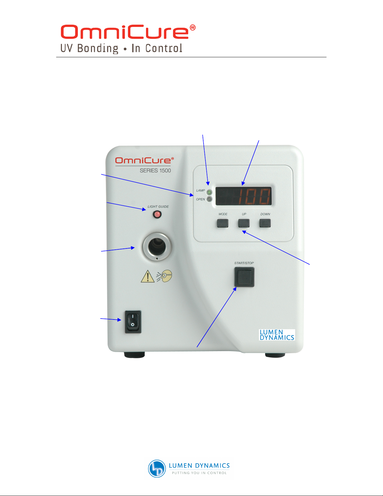
2.1 Front Panel .......................................................................................................2
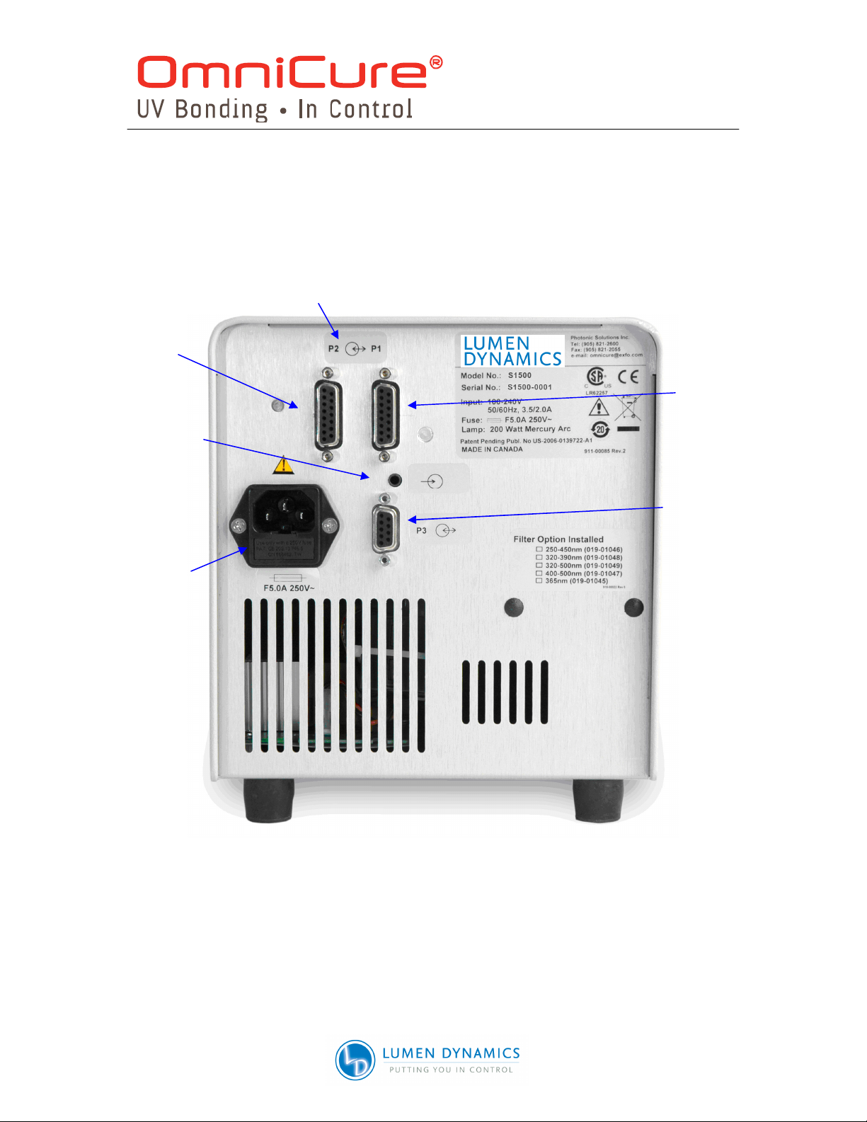
2.2 Rear Panel........................................................................................................3
3 Safety Precautions.................................................................................................4
4 Installing the Lamp Module ...................................................................................7
5 Inserting and Removing the Light Guide............................................................10
6 Powering Up and Powering Down ......................................................................11
7 Adjusting the Light Output ..................................................................................12
7.1 Adjusting the Light Output...............................................................................12
8 Locking and Unlocking the UP/DOWN Adjustment Button...............................13
9 Timed Exposures .................................................................................................14
9.1 Adjusting the Exposure Time ..........................................................................14
9.2 Running a Timed Exposure.............................................................................14
10 Interfacing with the S1500................................................................................14
10.1 Connection Options .....................................................................................14
10.2 Input/ Output Signals and Descriptions........................................................15
10.3 Audio Style Foot Pedal Connector: Signal Descriptions...............................21
11 Viewing the Accumulated Lamp Hours...........................................................21
12 Messages / Indicators ......................................................................................22
13 LED Indicators ..................................................................................................24
14 Clearing Audible Alarm ....................................................................................24
15 Remote Automated Control Requirements.....................................................25
15.2 Com Port Configuration: ..............................................................................25
15.3 Message Format and Protocol:....................................................................25
15.4 Command Descriptions: ..............................................................................26
15.5 Command Timing Specification: ..................................................................29
15.6 Sample Code:..............................................................................................29
16 Routine Care and Maintenance........................................................................32
16.1 Replacing the Lamp Module ........................................................................32
16.2 Replacing the External Fuses ......................................................................33
16.3 Replacing the Air Filter ................................................................................33
16.4 Replacing The Bandpass Filter....................................................................33
17 Troubleshooting ...............................................................................................34
18 Technical Specifications..................................................................................37
18.1 Lamp Module...............................................................................................37
18.2 Light Guide ..................................................................................................38
18.3 Power Input ................................................................................................38
18.4 I/O Ports (including RS-232)........................................................................39
18.5 USB Interface ..............................................................................................39
18.6 Environmental Conditions............................................................................39
18.7 Noise and the OmniCure S1500 ..................................................................40
19 Regulatory Compliance....................................................................................41

User Guide
- III –
19.1 Warning.......................................................................................................42
19.2 China RoHS ................................................................................................43
19.3 WEEE Directive (2002/96/EU) .....................................................................44
19.4 Mechanical Specifications ...........................................................................44
19.5 Miscellaneous..............................................................................................44
20 Warranty............................................................................................................45
20.2 Replacement Bulb Warranty........................................................................46
20.3 Returning your S1500 to Lumen Dynamics..................................................46
21 Component Part Numbers ...............................................................................47
22 Contact Information..........................................................................................48

User Guide
- IV –
Table of Figures
Figure 1 Front Panel........................................................................................................2
Figure 2 Rear Panel ........................................................................................................3
Figure 3 Lamp Housing Panel .........................................................................................7
Figure 4 Lamp Direction..................................................................................................8
Figure 5 Lamp Connection ..............................................................................................8
Figure 6 Active Low Signal Circuit Configuration: ..........................................................16
Figure 7 Active High Signal Circuit Configuration: .........................................................16
Figure 8 Rear Panel Sample Connection ......................................................................17
List of Tables
Table 1 “P1” Pin-Out .....................................................................................................18
Table 2 “P2” Pin-Out .....................................................................................................18
Table 3 “P3” Pin-Out .....................................................................................................20
Table 4 Foot Pedal Pin-Out...........................................................................................21
Table 5 LED Status .......................................................................................................24
Table 6 Unit Status........................................................................................................26
Table 7 Lamp Part Number ...........................................................................................32
Table 8 Replacement Filter Part Numbers.....................................................................33
Table 9 Message References........................................................................................34
Table 10 Front Panel LED Descriptions.........................................................................35
Table 11 Front Panel Button Descriptions .....................................................................35
Table 12 Component Part Numbers ..............................................................................47

User Guide
- 1 –
1 Introduction
The OmniCure® SERIES 1500 delivers the power, control and reliability never before
available in such a cost effective UV curing system. The S1500 joins the Lumen
Dynamics Group Inc. family of light systems offering the same high level of innovation,
quality and reliability that our customers have come to expect. Since 1982, Lumen
Dynamics Group Inc (formerly EXFO Life Sciences & Industrial Division) has combined
next generation optical engineering, state-of-the-art electronics and fiber-optics to
produce sophisticated technologies that employ light. Today Lumen Dynamics Group Inc
is a leading developer of light based systems for sectors ranging from manufacturing to
bio-medicine and we are unmatched in our commitment to quality and service.
The heart of the OmniCure S1500 is a proprietary 200-watt mercury short arc lamp with
an amazing 2000-hour guaranteed lifetime. This extended lifetime is made possible by
the proprietary technology incorporated into the design of the system. The lamp is
mounted in an elliptical reflector with a proprietary coating to provide excellent spectral
and power output.
Control for the OmniCure S1500 is provided by a rotary shutter / iris mechanism. The iris
is adjustable in 1% increments to provide very precise amounts of light to your
application.. Other standard features incorporated in the S1500 include: the pre-aligned
Intelli-Lamp® system, band pass filter, exposure timer, an accumulative lamp hour
meter, “lock out” protection, ,and a light guide status indicator. Units are configured for
standard curing applications.
We suggest that you read this manual to discover all features of the OmniCure S1500,
and how to use them.

User Guide
- 2 –
2 Getting Started
2.1 Front Panel
Figure 1 Front Panel
LIGHT
GUIDE
STATUS
LED
POWER
NO
/
OFF
SWITCH
LED
DISPLAY
LIGHT
GUIDE
PORT
START
/
STOP
BUTTON
-
SHUTTER
ACTIVATION
MODE
,
UP
/
DOWN
ADJUST
BUTTONS
SHUTTER
STATUS
LED
LAMP ON
STATUS
LED

User Guide
- 3 –
ADDITIONAL
I/O
(P2)
ANALOG JACK
(
FOOT PEDAL
)
AC RECEPTACLE AND
DUAL FUSE HOLDER
2.2 Rear Panel
Figure 2 Rear Panel
STANDARD
I/O
(P1)
D
-
SUB
9
PIN
RS
-232
PORT
(
P
3)
15
PIN DE
-
STYLE
PORTS FOR PLC
INTERFACING

User Guide
- 4 –
3 Safety Precautions
Glossary
Caution risk of danger – consult accompanying documents
Caution eye damage may result from directly viewing ultraviolet light – protective
eye shielding and clothing must be used at all times.
Input/Output Signals
Input Signal
The OmniCure S1500 is equipped with two safety sensors to protect the user from
accidental UV exposure. In addition, please observe the following precautions during
use. This series of cautions, warnings and dangers relate to the operation and
maintenance of the S1500. They are also presented throughout this User’s Guide where
necessary.
Warning
Eye damage may result from directly viewing the light produced by the lamp used in this
product. Always use the UV protective eyewear supplied with the unit and always turn
the lamp off before removing lamp housing cover.
Caution
Never look into the light emitting end of the light guide. The light could severely damage
the cornea and retina of the eye if the light is observed directly. Eye shielding must be
used at all times as well as clothing to protect exposed skin.
Warning
Always make sure the light guide is properly inserted into the OmniCure S1500 prior to
turning on POWER to the unit. This will minimize the risk of exposure to the UV light.
Warning
To reduce the risk of fire or shock, always replace the fuses with the same type and
rating. Always detach the POWER supply cord prior to attempting to replace fuses!
Warning
Disconnecting of the main supply source is only possible by unplugging the POWER
cord.

User Guide
- 5 –
Danger
This unit contains HIGH VOLTAGE components. It is recommended that ONLY
QUALIFIED TECHNICAL PERSONNEL perform any testing or repairs.
Monitoring the unit during manual operation
The Level of UV energy supplied by the OmniCure S1500 is sufficient to ignite
flammable substances. During manual operation, the unit must be attended at all times
by a qualified operator. The unit must not be left unattended while turned on. If an
operator leaves the work area of the unit, the POWER switch must be turned off.
Monitoring the unit during automated operation
The Level of UV energy supplied by the OmniCure S1500 is sufficient to ignite
flammable substances. Therefore, when the unit is operated unattended in an
automated environment, an alarm function must be provided by the user to indicate a
malfunction in the associated equipment used.
Warning
Hg – LAMP CONTAINS MERCURY, Manage in Accord with Disposal Laws, see:
www.lamprecycle.org or 1-800-668-8752
Danger
When unpacking or installing the lamp, always wear protective clothing and a face mask.
Operate lamp only in the OmniCure S1500 lamp housing. This prevents direct viewing of
the arc and in the case of lamp bursting, contains the lamp particles. In the rare
instance in which a lamp bursting occurs, and the mercury content is released, the
following safety precautions are recommended: all personnel should be immediately
evacuated from the area to prevent inhalation of the mercury vapor. The area should be
well ventilated for a minimum of 30 minutes. After the lamp housing elements have
cooled, the mercury residue should be collected with the use of a special absorbing
agent available from laboratory equipment suppliers.
Warning
Should this OmniCure S1500 unit be used in a manner not specified by Lumen
Dynamics Group Inc. the protection provided by the equipment may be impaired.
Warning
The method in which lamps are disposed of must comply with local rules & regulations
for disposal of hazardous materials. Lamps may be returned to Lumen Dynamics Group
Inc., providing they are returned in its original packaging. Lumen Dynamics Group Inc.
will dispose of them in the appropriate manner.
Caution
The lamp module’s operational life can be significantly shortened if it is handled
incorrectly. Do not touch the bulb’s glass envelope or the inside surface of the reflector.
Skin oils can cause the lamp module to fail prematurely.

User Guide
- 6 –
Caution
Prior to opening the unit and handling the lamp module, allow the lamp module to cool
down completely (approximately 20 min).
Caution
Any electronic equipment connected to the OmniCure S1500 must be IEC950 certified.
Cleaning
Clean exterior of the unit with a water dampened cloth and simple detergent only.

User Guide
- 7 –
4 Installing the Lamp Module
Note: Refer to Section 3 – Safety Precautions before proceeding
4.1.1 Be sure the AC POWER cord is disconnected from the unit.
4.1.2 Remove the screw from the lamp housing side panel using the tool provided
(fastened to the bottom face) and remove the panel from the unit cover.
Figure 3 Lamp Housing Panel
4.1.3 Carefully remove the lamp module from its container, holding only the ceramic
component and lamp rim.
Caution!
The lamp module’s operational life can be significantly shortened if handled incorrectly.
Be sure only to handle the ceramic surfaces and the lamp rim. Do not touch the bulb’s
glass envelope or the inside surface of the reflector. Skin oils can cause the lamp
module to fail prematurely
LAMP HOUSING SIDE PANEL

User Guide
- 8 –
4.1.4 As illustrated below position the lamp facing towards the front of the unit with the
POWER leads facing towards you. The lamp should be aligned so that the
leading edge of the reflector (lamp rim) fits into the mounting groove on the lamp
holder assembly.
Figure 4 Lamp Direction
4.1.5 Make sure the middle of the lamp is in position to fit into the spring clamp. Slide
the lamp until it snaps into the spring clamp. The leading edge of the reflector
(lamp rim) should fit snugly into the lamp holder recess.
Figure 5 Lamp Connection
LAMP HOLDER
POWER
LEADS
CERAMIC
COMPONENT
LAMP
RIM
S
PRING
C
LAMP

User Guide
- 9 –
4.1.6 Locate the 4-pin Intelli-Lamp sensor connector at the rear of the lamp module
and connect it to its mate located on the top of the lamp-housing wall.
Tip: the Intelli-lamp connector will only attach in the correct orientation. If you are having
difficulty attaching the connector, try rotating it by 180º.
Note: if the Intelli- lamp connector is not installed correctly, the lamp will not strike and
the “bulb” message will display when POWER is turned on to the unit.
4.1.7 Locate power connector with two leads and connect it to its mate located on the
side of the lamp-housing wall.
INTELLI
-
LAMP
CONNECTOR
POWER CONNECTOR
CENTER BAR AND LEAD
WITHIN THE CUTOUT

User Guide
- 10 –
4.1.8 Ensure the lamp anode cooling fin (bar) and lamp power lead, at the front of the
lamp, are centered within the lamp holder cutout. Rotate the lamp as required.
4.1.9 Replace the lamp housing side panel and tighten the fastening screw.
Note 1: If the lamp housing panel is not secured completely the lamp will not strike and
the “bulb” message will display when power is turned on to the unit.
Note 2: If the wrong type of lamp has been installed in your unit the message “E1” will
appear on the LED display. Refer to section 17 for troubleshooting information.
5 Inserting and Removing the Light Guide
Note: 3mm single leg liquid light guides are not compatible with the S1500
5.1.1 Ensure that the protective end caps are removed from both the input and output
ends of the light guide prior to installation.
5.1.2 Insert the light guide into the light guide port located on the front panel of the unit.
Push the light guide in until it seats with a second positive "click".
Tip: When the light guide is fully inserted, the LED above the light guide port will
illuminate green when POWER is on to the unit. If the light guide is not fully
inserted the LED will illuminate red.
Note: The shutter will not open if the light guide is not fully inserted.
5.1.3 During installation or removal, grasp the light guide on the strain-relief nearest
the input end of the light guide.
Note: Never grip the light guide during installation or removal in a place other than the
strain relief portion of the light guide.
5.1.4 To remove the light guide, firmly grip the strain relief near the light guide retainer
and pull out firmly.
Note: The OmniCure S1500 is designed for use with Lumen Dynamics Group Inc. Light
Guides. Lumen Dynamics Group Inc. cannot guarantee the performance of the
OmniCure S1500 if using light guides other than those supplied by Lumen
Dynamics Group Inc.

User Guide
- 11 –
6 Powering Up and Powering Down
6.1.1 Ensure that the lamp and light guide have been properly installed as per section
4 and section 5 and that the lamp housing panel is securely fastened.
6.1.2 Plug the OmniCure S1500 unit into a properly grounded AC outlet.
6.1.3 Turn on the mains POWER switch “I “, located on the front panel and check the
fan for airflow.
6.1.4 As soon as the LED display turns on it will display the version of software
currently programmed in the S1500 (i.e. r – x.x). Once the software version level
has been indicated, the display will reset after several seconds to the next
display mode.
6.1.5 The lamp will automatically turn on within 45 seconds and the lamp indicator will
illuminate. The display will flash during the warm up period for approximately 4
minutes. The display will stop flashing when the warm up period has completed.
Wait until the warm up period has completed before using the S1500 to perform
an exposure.
Note: If the lamp is turned off, and an attempt is made to turn it back on before it has
fully cooled, the “cool” message will appear on the display. The lamp will
automatically re-strike when the lamp has cooled.
6.1.6 To power down the unit, set the mains power located on the front panel to “0”.
6.1.7 10 exposures must be run to save any new exposure settings (intensity & timer)
into memory for it to remember next time the system is powered-up.
Lamp Warm
-
UP:
The ARC lamp has 3 distinct phases of operation;
1.Ignition.
2. Warm-up. Lumen Dynamics recommends 20 minutes of proper warm-up
and to ensure a stable optical output.
3. Stable Operation.
It is recommended that phase 1 and 2 are not interrupted. This can result in shortened
lamp life. The lamp must be allowed to warm-up uninterrupted.

User Guide
- 12 –
7 Adjusting the Light Output
Your OmniCure S1500 system includes an iris adjustment to control the intensity level of
the light output from the unit. The intensity level adjustment is only possible through the
DROP LED mode.
7.1 Adjusting the Light Output
Warning:
UV light will be emitted from the light guide. The light could severely damage the cornea
and retina of the eye if the light is observed directly. UV protective eye shielding must be
used at all times as well as clothing to protect exposed skin.
Note: The shutter will not open if the light guide is not inserted properly.
7.1.1 Press the start /stop button to open the shutter. The open LED indicator will
illuminate. The display will show three (3) digits (XXX). The three digit number
shown will indicate the percentage of maximum iris opening
Note: While in Level Mode, pressing the start/stop button will manually open the shutter
until the start/stop button is pressed again to close the shutter. The timer function will
not be activated.
7.1.2 Press the up button to increase the light output or press the down button to
decrease the light output. The % iris opening displayed will increase or decrease
by 1 for each time the up or down button is pressed.
Note: The shutter must be in the open position to make adjustments to the iris position.
7.1.3 For coarse adjustments, press and hold the up or down button to rapidly increase
or decrease the light output.
7.1.4 Press the start /stop button to close the shutter. The open LED indicator will turn
off.

User Guide
- 13 –
8 Locking and Unlocking the UP/DOWN Adjustment Button
8.1.1 Your OmniCure S1500 system allows you to disable the up/down buttons. When
the system is locked, no modifications to the set time or the optical output power
can be made. This can help to ensure process control when multiple operators
are using the same equipment.
Note: This feature is available only when the unit is set to “Timer” or “Level” modes.
Since the mode button is designed to make the mode jump to the next level i.e.
Timer if you are in Hours Mode & Level if you are in Timer Mode, you should pre-
set the mode to the previous level to lock the system in next level.
8.1.2 To Lock the up/down buttons:
A. Push and hold the mode button
B. While pressing the mode button, and within 2 seconds press the following
sequence of buttons:
Down - Up – up – up
C. After 2 seconds the message “LOC” will appear for 2 seconds. While the system
is locked, only the mode button and the start/stop button will function. If the up or
down button is pressed, the “LOC” message will appear for 2 seconds.
8.1.3 To Unlock the up/down buttons:
A. Push and hold the mode button
B. While pressing the mode button, and within 2 seconds press the following
sequence of buttons:
Down - Up – up – up
C. After 2 seconds the message “ULOC” will appear for 2 seconds. When the
system is unlocked, all of the front panel buttons will perform their respective
functions.

User Guide
- 14 –
9 Timed Exposures
Your OmniCure S1500 system includes a timer to automatically close the shutter after a
user selected amount of time. Adjustments to the exposure time can only be made when
the S1500 unit is in Timer Mode.
9.1 Adjusting the Exposure Time
9.1.1 The number shown will indicate the exposure time in seconds and tenth of
seconds (XXX.X).
9.1.2 Press the up button to increase the exposure time by 1/10 sec, or press the down
button to decrease the exposure time by 1/10 sec.
9.1.3 For coarse adjustments, press and hold the up or down button to rapidly increase
or decrease the exposure time.
9.2 Running a Timed Exposure
9.2.1 While in Timer or Lamp Hours mode, press the start /stop button. The shutter will
open and the exposure time will begin to count down. When the exposure time
has elapsed to zero, the shutter will close.
9.2.2 Running a timed exposure is only possible when the unit is set in either TIMER or
LAMP HOURS mode.
9.2.3 To view the remaining exposure time during a timing cycle, the unit must be set
in TIMER MODE. The display will indicate the remaining time as the unit counts
down.
Note: The open LED indicator will illuminate when the shutter is open. The shutter will
not open if the light guide is not inserted properly.
Note: To stop a timed exposure from running, press the start /stop button. The shutter
will close and the exposure time will reset after approximately 2 seconds. The
open LED will not be illuminated.
10 Interfacing with the S1500
10.1 Connection Options
10.1.1 The S1500 is designed to be fully automated both quickly and easily via PLC
control or computer control using the RS-232 port. All of the advanced features
ensuring process control and curing repeatability can be accessed through built
in standard optically isolated I/O signals. In addition to a foot pedal jack, there
are two PLC compatible I/O connectors that are 15 pin DE style (P1 & P2), the
RS-232 port is a D-Sub 9-position socket (P3). One RS-232 9 pin cable has been
provided with the unit to expedite implementation.

User Guide
- 15 –
10.1.2 The PLC I/O’s, foot pedal and RS-232 port are optically isolated from the control
S1500 control electronics. This has been done in order to maximize the S1500’s
immunity to noise and minimize its noise output.
10.2 Input/ Output Signals and Descriptions
10.2.1 Output Signals
•an output signal is said to be active when the output is ON
•a signal is said to be ON when the transistor side of its respective optocoupler is
conducting current
•the description of current conduction is dependent upon its’ end configuration,
selectable by the user
•an output can be configured as active high in which case the transistor is
sourcing current, or active low in which case the transistor is sinking current
Note: Refer to the following page for examples of output signal circuit configurations
The "digital" outputs have the following characteristics:
>polarized type, output device: optocoupler, NPN transmitter
>logic Level: uncommitted emitter and collector can be used as
active high or active low
>maximum voltage withstand: 30VDC capability (Vce):
>maximum carry current: 8 mA
Note: A signal is said to be active when the transistor side output of the optocoupler is
on/conducting and inactive when the transistor side of the optocoupler is off.
Other manuals for OmniCure 1500 Series
1
This manual suits for next models
3
Table of contents
Other Lumen Dynamics Group Industrial Equipment manuals
Popular Industrial Equipment manuals by other brands

Zimmer
Zimmer HWR Series Installation and operating instructions

ekwb
ekwb EK-Quantum Vector RX 6700XT user guide

Maxcess
Maxcess Tidland Advantage Series user manual

Stearns
Stearns 1-056-700 Series Installation and service instructions

Viking-Cives
Viking-Cives ROLLER PRO 120 owner's manual

Cirs
Cirs ZERDINE 040GSE user guide