Lumencor MIRA User manual

Regulatory Models
Lumencor utilizes regulatory model names for all certified and CE marked products. The regulatory model names are
traceable to all regulatory documentation, third party reports and certifications.
“Regulatory Model: Mira” is used as a representative model for all certified and CE marked Mira products.
Emissions
This equipment has been tested and found to comply with the limits of EMC directive 2014/30/EU and FCC part 15
(CISPR 11:+A1:2016). These limits are designed to provide reasonable protection against harmful interference when the
equipment is operated in a commercial environment. This equipment generates, uses, and can radiate radio frequency
energy and, if not installed and used in accordance with the instruction manual, may cause harmful interference to radio
communications.
Safety Certifications
TÜV SÜD America, CB Certification (IEC 61010-1:2010)
TÜV SÜD America, NRTLus Certification (UL 61010-1:2012/R:2016-04)
TÜV SÜD America, cNRTL Certification (CAN/CSA-C22.2 No. 61010-1:2012/U2:2016-04)!
TÜV SÜD America, EN Certification (EN 61010-1:2010)!
CE Marking
Low Voltage Directive (2014/35/EU)
EMC Directive (2014/30/EU)
RoHS Directive (2011/65/EU+2015/863/EU)
REACH Regulation (EC) No. (1907/2006/EC)
EU Declarations of Conformity can be found at https://lumencor.com/company/compliance
For EU customers discarding end-of-life Lumencor electrical and electronic equipment: Please submit an RMA request
with “Recycle product under WEEE” in the Description of Issues field.
For disposal in countries outside of the European Union: This symbol is only valid in the European Union (EU). If you wish
to discard this product, please contact your local authorities or dealer and ask for the correct method of disposal.
Lumencor, Inc. |14940 NW Greenbrier Parkway | Beaverton, OR 97006 USA | 503.213.4269 |www.lumencor.com!
Document Number 57-10001!
Revision D!
090921!
MIRA Light Engine Instruction Manual!2
Lumencor Light Engines as supplied, and as represented in this manual, meet safety and regulatory require-
ments!For Research Use Only.!If the light engine is incorporated into an instrument or system for a specific end-
use application, it is the responsibility of the system integrator to verify that the light engine, and the system into
which it is incorporated, meet all safety and regulatory requirements of that end-use application.

Table of Contents
1. Introduction
2. Precautions and Warnings
3. Installation and Operating Instructions
4. Spectral Output
5. Product Specifications
6. Routine Maintenance and Trouble Shooting
7. Customer Support
8. Warranty
MIRA Light Engine Instruction Manual 3

1. Introduction
The Lumencor MIRA light engine is a compact solid-state light source for fluorescence microscopy and other
bioanalytical applications. The MIRA light engine incorporates efficient thermal management, requiring no fan and
providing quiet and vibration-free operation. This enables direct coupling to the fluorescence epi-illumination port of a
microscope.
The light engine provides four distinct color bands of light output that are controlled using either manual control knobs on
the side panel or the light engine control pod accessory (part number 83-10007). The COLOR knob located on the side
panel is used for on/off control, selection of color channels and for enabling external tablet control. The INTENSITY knob
provides four different levels of output attenuation between 100% and 10% of maximum.
MIRA Light Engine Instruction Manual!4

2. Precautions and Warnings {Précautions et mises en garde}
A few simple practices will ensure trouble-free operation for the life of the light engine.
Les quelques règles simples suivantes permettront d’assurer un fonctionnement fiable pendant toute la durée de service
de la source lumineuse.
Safety Instructions:
Please read and follow all safety instructions provided BEFORE using your new MIRA light engine. Failure to comply with
the safety instructions may result in fire, electrical shock, or personal injury and may damage or impair protection provid-
ed by equipment. Please save all safety instructions.
Instructions de sécurité:
Veiller à lire et à respecter toutes les instructions de sécurité fournies AVANT d’utiliser le nouveau MIRA afin d’écarter les
risques d’incendie, de décharge électrique, de blessure corporelle et de possibles dommages ou défaillance de la pro-
tection offerte par l’appareil. Conserver toutes les instructions de sécurité.
Safety Definitions {Définitions relatives à la sécurité}:
Warning: Statements identify conditions or practices that could result in personal injury.
Avertissement:déclarations qui identifient des situations ou des pratiques susceptibles d’entraîner
des blessures corporelles. !
Caution: Statements identify conditions or practices that could result in damage to your equipment.
Attention:déclarations qui identifient des situations ou des pratiques susceptibles d’endommager le matériel.
Safety Items {Mesures de sécurité}:
Warning: DO NOT use an unapproved power supply. The Lumencor supplied 9V, 4.45A external power supply is
required for use with the Mira light engine. It is imperative that the alternative power supply has output over-current
protection, as the power input of the Mira is not fused. The DC power supply must have the AC power cord connected
to a receptacle with a protective safety (earth) ground terminal.
Avertissement!: NE PAS utiliser une alimentation électrique non homologuée. Le Lumencor fourni 9V, 4.45A
alimentation externe est nécessaire pour une utilisation avec le moteur de lumière Mira. Il est impératif que le bloc
d'alimentation de remplacement a une sortie protection contre les surintensités, comme l'entrée de puissance du Mira
est pas fusionné. L' alimentation en courant continu doit avoir le cordon d'alimentation relié à une prise avec une sécurité
de protection ( terre) du sol.
Warning: DO NOT look into the output of the light engine. The brightness of this light source is higher than most
commercial lighting fixtures and is required to couple directly into a microscope or other bioanalytjcal instrument.
Avertissement: NE PAS regarde directement la sortie de la source lumineuse. L’intensité lumineuse de cette
source est supérieure à celle de la majorité des appareils d’éclairage disponibles dans le commerce et est conçue pour
un raccordement direct à un microscope ou autre appareil de bioanalyse.
MIRA Light Engine Instruction Manual 5

Warning: DO NOT turn on the light without!the output safely!directed!into an enclosed optical path. !DO NOT
point the light output directly onto any flammable or burn-susceptible material.!This includes all animal or vegetable tis-
sues, plastics, fabrics, paper and liquids.
Avertissement:NE PAS allumer la lumière sans que la sortie ne soit dirigée de manière sûre dans un chemin
optique inclus. NE PAS pointer la sortie de lumière directement sur tout matériau inflammable ou susceptible de brûler.
Cela comprend tous les tissus, les plastiques, les tissus, le papier et les liquides animaux ou végétaux
RISK GROUP 3
Warning: Possibly hazardous optical radiation emitted from this product. Do not look at operating lamp. Eye injury may
result.
Warning: Infrared (IR) emitted from this product. Do not look at operating lamp.
Warning: UV emitted from this product. Avoid eye and skin exposure to unshielded product.
GROUPE DE RISQUE 3
Avertissement: Infrarouge (IR) émise par ce produit. Ne regardez pas la lampe d'exploitation.
Avertissement: Rayonnement optique Peut-être dangereux émis par ce produit . Ne regardez pas la lampe d'exploita-
tion. Une blessure oculaire peut entraîner.
Avertissement: UV émis par ce produit . Évitez les yeux et la peau exposition au produit non blindé.
Caution: DO NOT open the unit. There are no serviceable parts inside and opening the light engine enclosure will void
the manufacturer’s warranty.
Attention: NE PAS ouvrir l’appareil. Il ne contient aucune pièce réparable et l’ouverture de son boîtier a pour effet
d’annuler la garantie.
Caution: DO NOT set liquids on the light engine. Spilled liquids may damage your light engine.
Attention: NE PAS placer de liquide sur la source lumineuse. Les liquides renversés peuvent endommager la
source lumineuse.
Caution: DO NOT drop the light engine. It contains glass optical components that could be damaged or misaligned
by the shock produced by a drop onto a hard surface.
MIRA Light Engine Instruction Manual!6

Attention: NE PAS laisser tomber la source lumineuse. Elle contient des composants optiques en verre suscepti-
bles d’être endommagés ou désalignés par le choc résultant d’une chute sur une surface dure.
DISCLAIMER: Lumencor shall not be liable for injury to the user or damage to the product resulting from the
MIRA light engine being used in a way for which it was not intended and in complete disregard for any post-
ed safety precautions and warnings.
AVIS DE NON-RESPONSABILITÉ: Lumencor décline toute responsabilité pour les blessures corporelles ou
les dommages au produit résultant d’une utilisation du MIRA autre que celle prévue et du mépris total de les
mesures de sécurité et mises en garde affichées.
3. Installation and Operating Instructions!
3.1 Contents
The MIRA light engine ships with the following list of standard components.
1. MIRA light engine configured with an output adapter for coupling to a specific
microscope.
MIRA Light Engine Instruction Manual 7
AC Power Cords
Region
Part Number
North America
29-10002
Europe
29-10005
United Kingdom
29-10004
Israel
29-10008
Australia/New Zealand
29-10024
Figure 1. MIRA light engine rear panel showing
identification label, input receptacles for DC power
supply, USB connection to light engine Control POD
(“external”) and electronic shutter (“gate”)

2. A 9 V, 4.45 A power supply (Lumencor p/n.
27-10017).
3. A USB A (M) to USB A (M) cable (p/n
29-10057) for connection to the optional
light engine control pod accessory.
4. A region-specific 6 ft AC power cord for the
power supply (see above table).
The model name and unique 4- or 5- digit serial
number of the light engine are marked on an
identification label affixed to the back panel
(Figure 1).
Performance specifications for individual light
engines are listed on the certificate of
conformance included with the shipping
documents e-mailed to the customer. It is
important to retain the certificate of
conformance for reference. In the event that
the light engine is sold or transferred, the
certificate of conformance should be conveyed
to the new owner
3.2 Installation
NOTE: Any end-product/system incorporating or coupled to a Lumencor Light Engine shall be fully evaluated to verify all
applicable safety and regulatory compliance requirements prior to
use.
Take necessary precautions to protect yourself and others
from the high intensity light when turning on the unit. The
MIRA light engine should be coupled to a microscope before it is
turned on. BE AWARE that although the human visual system
does not register the wavelengths of light from the violet color
channel, exposure can quickly produce eye damage. When setting
up the MIRA light engine, be sure that the output adapter is
securely attached to the appropriate illumination port of the
microscope. Usually this will be the fluorescence epi-illumination
port. Be careful to properly support the MIRA light engine until it is
securely attached to the instrument.
The MIRA light engine must be operated in a non-condensing
environment (dew point <10ºC with controlled ambient temperature <30º C). Restricting the airflow will cause the unit to
operate at elevated temperatures and could result in decreased product life and/or premature failure. The power supply
should be plugged into the DC power connector at the back of the light engine. The green ”power” indicator light on the
rear panel (Figure 1) illuminates when electrical power is being drawn by the light engine.
3.3 Manual Operation
MIRA Light Engine Instruction Manual!8
Figure 3. USB connectors on the rear of
the light engine control pod.
Figure 2. MIRA light engine with with output adapter for coupling to Nikon
Ti/Ni/Ci microscope epi-illumination port.

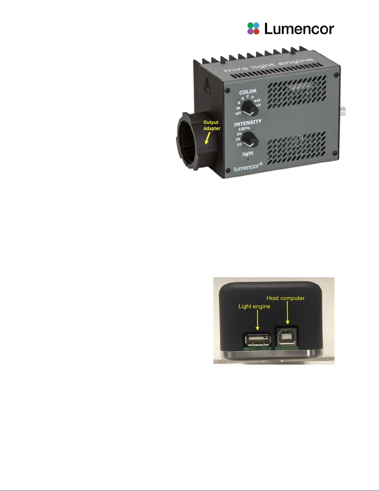
Two control knobs are located on the side panel (Figure 2). The “COLOR” knob allows the user to select light output
from any or all of the four color channels. The selections are “V” for violet, “C” for cyan, “G” for green and “R” for the red
color channel. The “W” setting is for white light, when all four color bands are simultaneously illuminated. The “ext”
setting allows the MIRA light engine to be controlled using the Light Engine Control Pod (see below). There are two “off”
settings at opposite ends of the knob range. Both of these “off” settings turn the electrical power to the light engine off.
The “INTENSITY” control knob sets four different levels of output attenuation between 100% and 10% of maximum. This
setting is applied to the current source selection according to the position of the “COLOR” knob. It is recommended that
the intensity be set to the “10%” position when a source is first turned on, and then increased as necessary. A yellow
indicator light below the INTENSITY control knob on the side panel (Figure 2) alerts the user that light output is active.
3.4 Operation Using the Light Engine Control Pod
1. Connect the USB A port of the light engine control pod accessory (83-10007) to the USB A (“external”) port on the
MIRA using the USB-A to-USB A cable (29-10057) [1].
2. Move the COLOR control knob on the side panel of the MIRA) to the “ext” position [2].
3. Press and hold the right button on the pod until a menu of light engines appears. Turn the rotary dial to select “MIRA”
from the menu. Press the right button again to return to the main (0–100 analog intensity) display screen.
4. WARNING: Before turning the light output on, be sure the output port of the MIRA is safely directed into an enclosed
optical path (e.g. microscope epi-illuminator input port).
AVERTISSEMENT!:avant d'allumer la sortie de lumière, assurez-vous que le port de sortie du MIRA est dirigé en
toute sécurité dans un chemin optique fermé (par exemple, le port d'entrée de l'épi-illuminateur du microscope).!
5. Press the left button on the pod to select the desired color channel. Successive presses will cycle through the
available color channels.
6. Press the right button to turn the selected light source on [3]. The yellow ”light” indicator on the MIRA side panel
(Figure 2) alerts the user that light output is active. Adjust the output intensity using the rotary dial on the pod [4].
Press the right button again to turn the selected light source off.
7. Press and hold the left button to view a digital rendition of the intensity setting [5]. Press the right button to return to
the main display screen.
8. Further details of control pod operation are available at Lumencor’s Operating Instructions site.
Notes
[1] The MIRA does not currently support pass-through control from a host computer.
[2] This will activate electrical power supply from the MIRA to the pod.
[3] There is no warm-up time; the light engine output stabilizes less than 1 second after the light output is switched on.
Light output can be switched off during intervals when it is not required for active viewing or data collection.
[4] Output intensity can be set from 0–100% in 1% increments; however operation in the 0–5% range is not
recommended. Turning the rotary dial to zero intensity automatically turns the selected light source off. Press the right
button to turn the source back on again.
[5] The current intensity settings are internally stored. When the pod is powered down, the settings are retained and will
be restored at the next restart.
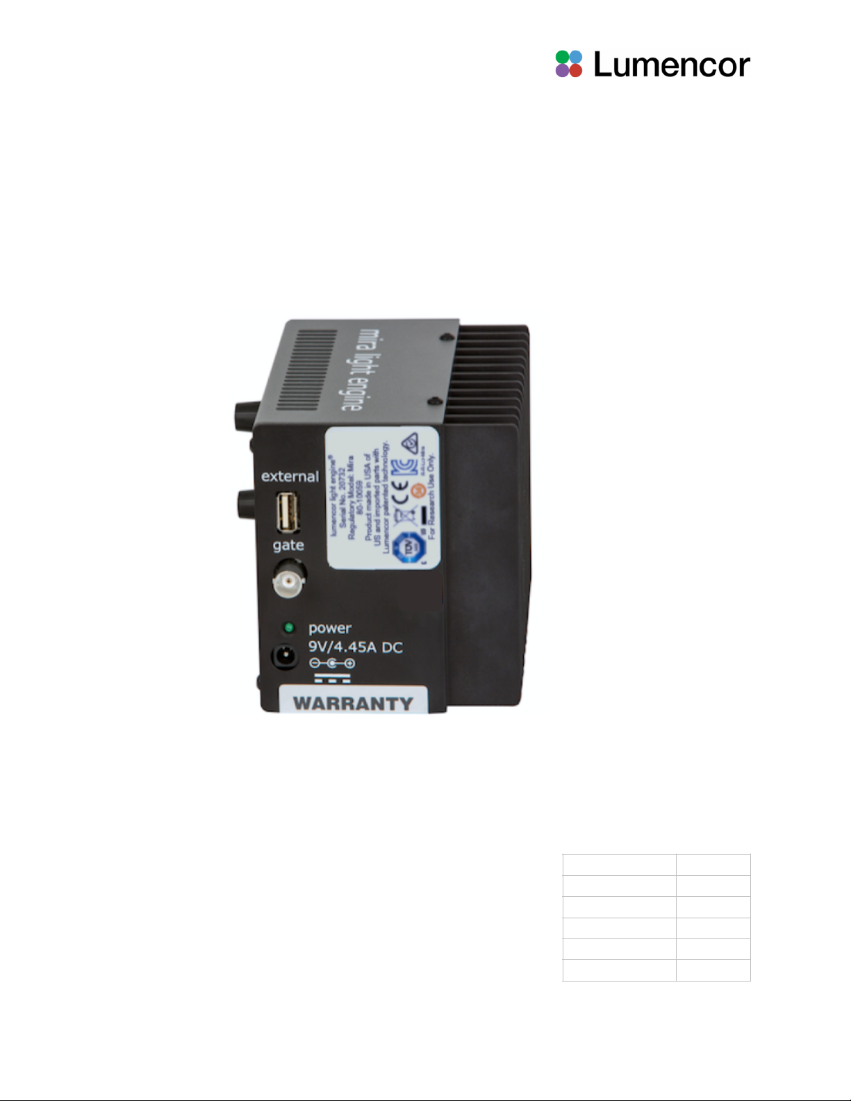
3.5 Using the Gate Connector
The MIRA light engine output can be turned on/off electronically using the electronic shutter function accessed through
the BNC “gate” connector located on the rear panel. A > 3.3 V “high” signal applied to the BNC connector will turn the
source on while a <1.5 V signal turns the source off. The MIRA light engine can support an on/off switching rate up to
approximately 1 kHz. Note that DC control levels applied to the gate connector DO NOT trigger selected color channels.
Light sources must first be enabled using the side panel COLOR control knob or the touchscreen control tablet.
MIRA Light Engine Instruction Manual 9

Switching the gate connector to ground will then shut off light output. Restoring the input level to >3.3 V will restart light
output.
4. Spectral Output!
The normalized spectrum shown below is representative of the MIRA light engine output. External bandpass filters can
be used to restrict the wavelength range of each color channel.
5. Product Specifications!
The MIRA light engine must be operated and stored within the environmental conditions specified. Performance
specifications for individual light engines are listed on the certificate of conformance included with the shipping
documents e-mailed to the customer. It is important to retain the certificate of conformance for reference. In the event
that the light engine is sold or transferred , the certificate of conformance should be conveyed to the new owner.
Certificates of conformance are also recorded in Lumencor’s database and copies can be requested by e-mail to
techsupport@lumencor.com. The request message must include the 4- or 5- digit serial number of the light engine.
6. Routine Maintenance and Troubleshooting!
Remove any built-up dust or accumulation on the vent holes. A vacuum may be used to remove debris so that a steady
supply of air is available for cooling. It is recommended that the vent holes be cleaned by a gentle suction device at least
every 6 months and more often in dusty or smoke-filled environments.
There are no user-replaceable components or sub-assemblies in MIRA light engines. Opening the light engine enclosure
will void the manufacturer’s warranty.
MIRA Light Engine Instruction Manual!10
Figure 4. Representative spectral output of the MIRA light engine

7. Customer Support!
For technical support of the MIRA light engine, please contact Lumencor by phone at 503.213.4269 or through e-mail at
techsupport@lumencor.com. Any light engine return to Lumencor for repair or refurbishment requires a return material
authorization (RMA) number. To request an RMA number, fill out and submit the online request form. Units that are
returned to Lumencor without an RMA number will not be accepted. Notification of RMA issuance, together with
shipping instructions will be sent to the customer e-mail address provided on the request form. It is the customer’s
responsibility to properly package and safely ship products to Lumencor. The customer is responsible for selecting the
method of shipment to Lumencor and paying for the shipment. If it is determined that necessary repairs or refurbishment
are covered by warranty, then Lumencor will pay for return shipment to the customer. For out-of-warranty service work,
Lumencor will evaluate the light engine upon receipt and then provide a quotation for the cost of necessary repairs or
refurbishment. Work will not begin until a purchase order for the quoted services has been received.
8. Warranty!
The MIRA light engine comes with an 18 month warranty starting from the date of shipment from Lumencor’s factory in
Beaverton, OR. Please fill out and submit the online warranty registration form . This will facilitate provision of warranty
service should it be required.
MIRA Light Engine Instruction Manual 11
Specification
Detail
Temperature
Operating
32 to 95° F (0 to 35° C)
Non-operating
-4 to 158° F (-20 to 70° C)
Humidity
Operating and non-operating
0 to 80% relative humidity, non-condensing
Altitude
Operating
0 to 10,000 feet (3,048 meters)
Non-operating
0 to 45,000 feet (13,176 meters)
Dimensions (WxLxH)
4.25 in x 6.0 in x 4.25 in / 10.5 cm x 15 cm x 10.5 cm
Weight
3.3 lb / 1.5 kg
Input Power Requirements
9 VDC / 4.45 A, 40 W maximum, power supply included
Gating Speed
On/Off rate up to 1 kHz
Warm-up Period
1 s
Protection
IP Rating of X0
Sound Level
Sound Level at 1 m = 0 db(A)
Connections
USB A for Light Engine Control Pod and one BNC connection for TTL
gating
Warranty
24 months parts and labor for end users
Table of contents
Other Lumencor Lighting Equipment manuals