Lumingen SLD-PK Instruction Manual

Version: IAE Visit us at www.lumingen.com or Call us at 1-604-371-4112
SLD-PK Area Flood LED Lighting
IMPORTANT SAFETY INSTRUCTIONS Mesures de Sécurité à Respecter
This product must be installed in accordance with the applicable installation code
by a person familiar with the construction and operation of the product and the
hazards involved.
Ce produit doit être installé selon le code d’installation pertinent, par une per-
sonne qui connaît bien le produit et son fonctionnement ainsi que les risques in-
hérents.
-
Convient aux emplacements mouillés.
Ne pas enlever l’ecran protecteur.
Mount ce
luminaire utilisant uniquement le support de montage fourni par le fabricant ou similaire.
----
Remplacer uniquement avec de nouveaux intempéries twist-on connecteurs de fils.
Les fils d’alimentation doivent convenir pour 90OC.
Attention—risque de choc.
Enlevé luminaire pour l’entretien.
Garder toujours la
plaque de protection en métal et les vis en place. Retirez uniquement si nécessaire.
Ne pas utiliser dans les logements.
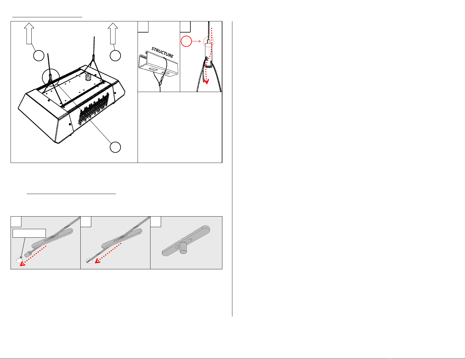
Ultra-versale high output lighng luminaire to be installed via Suspension, Surface/
Wall, Pole, or Pendant Stem.
264579
Wiring from LED Driver
to AC Supply, or LED
Driver Terminal Block
Colouring
Wiring for 0-10V
Dimming, from
Separate Cord
AC/Line Supply Connecon (Black)
AC/Neutral Connecon (White)
Earth Ground Connecon (Green)
Dim + Connecon (Violet/as Labeled)
Dim ‒ Connecon (Gray/as Labeled)
A
B
Your locaon
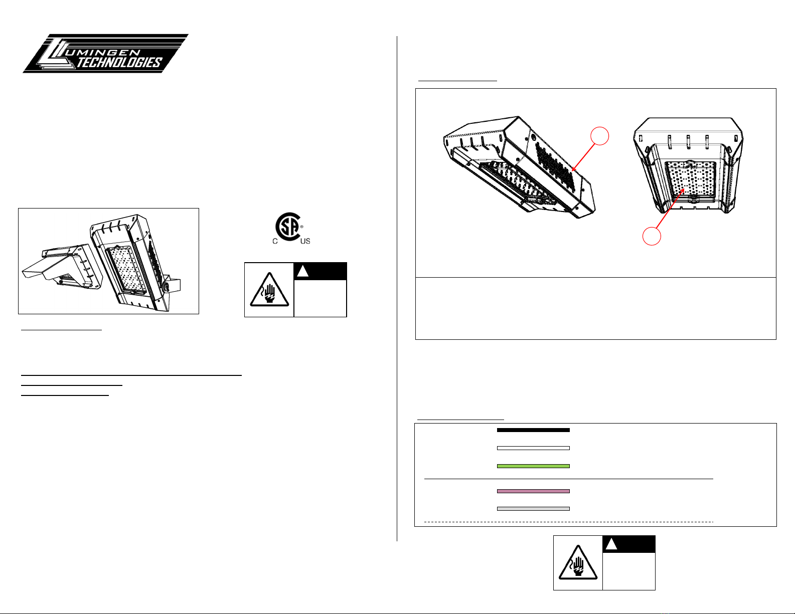
Holes (see point A) on the side of the housing allow for venlaon of heat from the housing. Do not mount
xture where this venlaon may be obstructed.
Lens cover (see point B) protects sensive LED components from water damage and is rated for IP67 appli-
caons. Do not remove lens cover, as this will compromise the water protecon of the xture.

Version: IAE Visit us at www.lumingen.com or Call us at 1-604-371-4112
Loop around
appropriate
structural element.
2
11
Supplied Hardware:
• Cable to loop around structure
• Gripper Assembly, pre-assembled to
luminaire
Slide the Cable through the top of the
Gripper Assembly. Gripper allows cable to
move in one direcon only.
To slide cable in opposite direcon, hold
down the top of Gripper (see point C).
Tie up and secure the excess cable.
C
123
Part of the suspension kit is assembled into the luminaire. However, if for some reason the suspension kit
not completely assembled into the xture. Follow the following procedure to reaach the cable into the
luminaire.
Please, do not disassemble the cable gripper assembly. Crical components may dislodge from their normal
posion and may cause the gripper assembly to be faulty.
For all other issues regarding installaon of the suspension kit, please contact Lumingen Technologies.
Top of Fixture Top of Fixture Inside of Fixture
Normal Seated Posion
Ø6.4mm Hole
12

Version: IAE Visit us at www.lumingen.com or Call us at 1-604-371-4112
1(The fasteners highlighted here
are not provided with xture)
Fixture may be oriented in
various ways. Contact Lumingen
for alternave bracket
mounng opons.
Step 1. Secure bracket to
mounng surface by the sup-
plied bolt paern on the brack-
et either by bolng to surface or
by threaded inserts.
Step 2a/2b. Adjust the orienta-
on of the xture. Re-ghten
depicted bolts on both sides of
the xture. Bolts depicted in
step 2 are supplied with xture.
2a 2b
11
Slot paern for mounng to a
surface with the yolk mounted
bracket.
Bolt paern is posioned cen-
ter in the bracket.
For alternave bolt paerns,
please contact Lumingen Tech-
nologies.
2b
2a 1
Bracket and Bolt
Posions for Large
Tilng Angles
Bracket and Bolt Posi-
ons for Down Lighng
or Limited Tilt

Version: IAE Visit us at www.lumingen.com or Call us at 1-604-371-4112
Pole mount posions may
be oriented in various
posions. Consult with
Lumingen for more infor-
maon.
1
2Step 1. Hex Bolt and Jam Nuts depicted in this step are
provided. Loosen nuts and bolts on the pole mount as
shown. Fit the slip er over the pole as far as it can go.
Both bolts in the slip er must be able to secure against
the pole. Tighten the bolts (see point E). Check that the
slip er will not come o the pole. Next ghten the jam
nuts threaded over the bolt (see point D) against the slip
er body. This is to migate loosening from vibraons
in the environment.
Step 2. If the xture is not already aached to the slip
er, t the bracket on the xture over the slip er. A
single set of M16 socket head bolt and M6 socket head
cap screw with their respecve washers and nuts are
used to assemble the xture/bracket to the slip er.
Step 3. The xture may also be lted at this point. Each
hole posion in the paern lts the xture by 10°. Maxi-
mum upward lt is 90°. Maximum downward tilt is 30°.
Replace M6 socket head cap screw to secure the lt
angle of the xture.
Use the appropriate tools and cauon to lt, aim, and
secure the xture.
3
(2-3/8”)
E
D
0°
+90°
-30°
Proper posion of jam nuts
Fixture may come pre-aached to slip er

Version: IAE Visit us at www.lumingen.com or Call us at 1-604-371-4112
-
11a 1b
22a
33a
4Finished Assembly Step 1. Locate the areas where the cut-o
visor will be aached.
Step 1a. Loosen screws (2x screws) at the top.
Removal of screws are not necessary.
Step 1b. Detach screw and nut ( 2x screw/nut
sets) from L-bracket at the boom.
Step 2/2a. Posion cuto visor with the L-
bracket. Slot paerns on parts should overlap
but it is not necessary to align the slots. L-
brackets will be posioned on the inside of
the cut-o visor. Assemble the screw/washer/
nut sets as shown (on both sides).
Step 3/3a. Align top of visor so that the top of
the visor t over their respecve screws.
Tighten screws on both sides
Step 4. Re-aach/Tighten/Re-ghten all
screws handled in the cut-o visor assembly
phase. Verify visor is properly secure.
1a
1b
2a
3a
-
-
Please note:
Cut-o visor orientaon is pre-dened and is only appli-
cable with certain installaon conguraons. Please
contact Lumingen for more informaon.

Version: IAE Visit us at www.lumingen.com or Call us at 1-604-371-4112
Depending on the applicaon, the
shoebox bracket can be separated
to ease nal installaon. To do so,
Detach the following nut-bolt sets:
2x 3/8in-16 nut-bolt sets (see point
F) and 4x 1/4in-20 nut-bolt sets
(see point G).
Aach the bracket to the square
post using the bolt paern shown
by point H. To complete installa-
on., ghten all bolts and screws
used to install the xture to the
post.
The bolt paern shown by point H
shall be used to aach the xture
to the square post.
The center hole shown by point J
shall be used in conjuncon with a
strain reliever (not provided).
Any hardware used to aach the
xture to the square post or surface
is not provided.
Any sealing of the bracket to any
post or surface is not provided with
the xture.
SQUARE POST
(NOT PROVIDED)
G
F
F
G
HJ

Version: IAE Visit us at www.lumingen.com or Call us at 1-604-371-4112
Other Lumingen Lighting Equipment manuals