Emergency Lighting Interface LUT-ELI-3PH |Installation Guide
LUT-ELI-3PH Installation Guide Lutron®|3
1234 5678 910111213141516
CLASS 2 LOW VOLTAGE WIRING
12345Power Status Program Burn-In
123
378910 11 12 13 14 15 16
CLASS 2 LOW VOLTAGE WIRING
12345Power Status Program Burn-In
123
45612
´FACP´N/C
CONTACTS
´FACP´N/O
CONTACTS
CLASS2LOWVOLTAGEWIRING
GND
SENSE
DRAIN
MUX
MUX
+24VFW
COMMON
NOTUSED
LED1
LED3
LED2
RADIOTOUCH
PHASE
FACF
S1
TEST
12 11 10 98765432112 11 10 987654321
RadioT o uchTM
C o o p e r sbur g, PA 1 8 0 3 6 U S A
R T A-RX-F-SC
LISTED243C
Ind.Cont.Eq.
12
3456789101 1 12 13 14 1 5 16
Occ.Com
OccSig
24V
CirCom
CCO1
CCO2
CCO3
CCO4
CCO5
CCOCom
+
_
PELV(Class2:USA)
PWR STAT PROG 100Hr/100%
®
PSSig
P/N500-10634
©
2006LutronElectronicsCo.,Inc.
12345
ON
PowerWiringCableadod ePoderCâblaged'alimentation
DistributionPanel
PaneldeDistribución
PanneaudeDistribution
Ground/Tierra/Terre
Neutral/Neutro/Neutre
Black/Negro/Noir
Green/V er de/Vert
White/Blanco/Blanc
Red/Rojo/RougeOR
Orange/Anaranjado/Orange*
SwitchedHot/InterruptorVivo/CourantCommuté
DimmedHot/AtenuadorVivo/CourantTamisé*
Dimmed Hot is for use only with Lutron Hi-Lume FDB-series or Eco-10 ECO-series dimming ballasts.
El Atenuador V ivo es para ser utilizado ú nicamente con las series de balastos
de atenuaci ó n Hi-Lume FDB o Eco-10 ECO de Lutron.
Courant T amisé doit être utilisé seulement avec le Hi-Lume FDB-series ou avec
le ballast de gradation Eco-10 ECO-series de Lutron.
P/N 500-10634
*
*
*
Hot/Vivo/Chargé
For 120 V~ use black wire, cap red. For 277 V~ use red wire, cap black.
Blue/Bleu/Azul
120V277V
*
USA,Canada
1-800-523-9466
Mexico
1-888-235-2910
®
www .lutron.com
RTA-RX-F-SC
15V
CONFIGURACIONES
REGLAGES
SETTINGS
R e fertotheInstallersGuideformore
detailedinstructions.
ConsultelaGuíadeInstaladorespara
informaciónmásdetallada.
RéférerauGuided’installationpourplusde
renseignementsdétaillés.
120/277V60Hz
16AMax.
0-10
V
Red&Black/Rojo&Negro/Rouge&Noir
LUT-ELI-3PHUnit RadioTouchUnitA RadioTouchUnitB
120/277V
feedbackup/
Emergency
power
120/277V
feedbackup/
Emergency
power
FlipDip
Switch2to
thedown
position
FlipDip
Switch2to
thedown
position
(2)Signal
(6)CircuitCommon
Toadditional
RadioTouch
controllers
(100maximum)
AdditionalRadioTouchControllerforBackup/
EmergencyLight(s)
Availablepowerfromthisunit
fordaylightsensorsmustbe
deratedto15mA.
(8) (2)(7) (4)(1) (6)
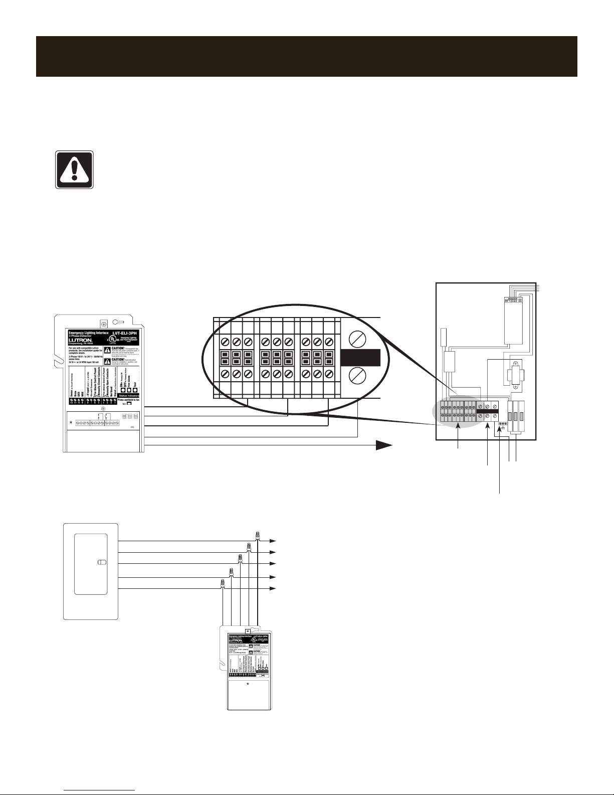
Installing a LUT-ELI-3PH Unit in a
RadioTouch®System (continued)
NEC®Class 2/PELV Connections
Note: Whenwiringforabackup/emergencysourceof
power,theRadioTouchController(modelsRTA-RX-F,
RTA-RX-F-SC,RTA-RXSW),beingusedforthebackup/
emergencylights(UnitAandB)cannotbecontrolledby
anoccupancysensor.UnitsAandBDIPswitch2must
beinthedownposition.
NEC Class 2/PELV Wiring to RadioTouch
Controllers
OneLUT-ELI-3PHcanbeconnectedinparallelwithup
to100RadioTouchControllers.
1. FlipDIPswitch2ontheRadioTouchControllertothe
downposition.
2. Disconnectanyoccupancysensorswiredtothe
RadioTouchController.
3. Makethefollowingconnections.
From LUT-ELI-3PH Unit To RadioTouch Controller
Terminal8(+VInput) Terminal4(24V ),UnitAonly
Terminal7
(CircuitCommon)
Terminal6(CirCom)
Terminal1(Signal) Terminal2(OccSig)
Test the System
Pleaseperformthefollowingteststoensureproper
installation.
1. TurnoffoneoftheNormal(Non-Essential)phase(s)
breaker(s)thattheLUT-ELI-3PHunitismonitoring.
You should see the following:
•AlllightscontrolledbyEmergency(Essential)panel
willgotoFULLINTENSITY(factoryset).
•PHASEON/OFFstatusIndicator(green)willturn
OFFastheabovetestcreatesaphasefailure.
•Uponturningthebreakerbackon,alllightsshould
returntotheirpreviousintensity.
2. PressandholdswitchSW1ontheLUT-ELI-3PHunit.
You should see the following:
•TESTLED(orange)willturnON.
•AlllightscontrolledbyEmergencyRadioTouch
controllerwillgotoFULLINTENSITY(factoryset).
Note: PHASEON/OFFstatusindicator(green)will
notturnOFFastest#2doesnotcreateaphase
failure.
•UponreleasingswitchSW1,alllightswillreturnto
theirpreviousintensities.
Note:OnlyoneRadioTouchunitcanhaveits
24V (number4)terminalconnectedtoterminal
8(+VInput)ontheLUT-ELIunitregardlessofthe
numberofwiredRadioTouchunits.
(2) (6)