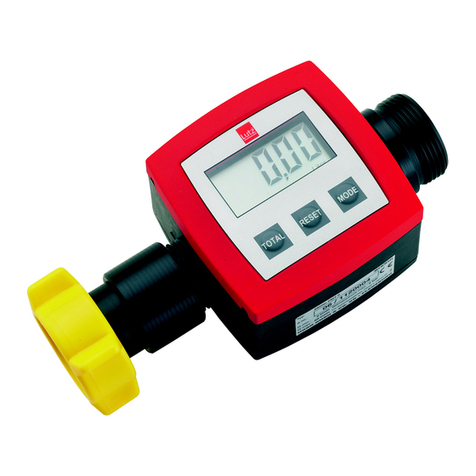
Lutz RM10 User manual

0698-701 Relay module - 04/2021
Translation of the original instructions
RELAY MODULE / POWER SUPPLY UNIT
Type
RM10
RM30
NG10
en
Please read this manual before starting up.
To be retained for future reference.

2
0698-701 Relay module - 04/2021
en

3
0698-701 Relay module - 04/2021
en
Table of Contents
A. General ............................................................................................................................................ 4
1. Concerning this manual ............................................................................................................. 4
1.1 Terms .................................................................................................................................. 4
1.2 Target groups...................................................................................................................... 4
1.3 Associated applicable documents....................................................................................... 4
1.4 Warnings and symbols ....................................................................................................... 5
1.5 Latest state.......................................................................................................................... 5
1.6 Copyright ............................................................................................................................ 5
2. Safety.......................................................................................................................................... 6
2.1 General safety information................................................................................................. 6
3. Scope of supply .......................................................................................................................... 7
4. Marking .................................................................................................................................. 7
5. Modular Flow Meter System TS.................................................................................................. 8
6. Modular Flow Meter System HDO .............................................................................................. 9
B. Relay module RM10/RM30 and power supply unit NG10............................................................... 10
1. Proper use ................................................................................................................................ 10
1.1 Technical data ................................................................................................................... 12
1.2 Application in explosion hazard areas .............................................................................. 12
1.2.1 Electrical data........................................................................................................... 13
1.2.2 Applied standards.................................................................................................... 13
1.3 Prevention of obvious misapplication (examples)............................................................ 13
2. Installation ............................................................................................................................... 14
2.1 Retrottingtherelaymodule/powersupplyunit............................................................. 14
2.2 Connection for automatic mode....................................................................................... 15
2.3 Flow meter with separate installation
of relay module/power supply unit and operating unit ................................................... 18
2.4 Flow meter with relay module/power supply unit
and separate installation of operating unit ...................................................................... 20
3. Maintenance and servicing ...................................................................................................... 22
3.1 Changing the fuse in the relay module/power supply unit ............................................. 22
C. Repairs .......................................................................................................................................... 24
D. Traceability...................................................................................................................................... 24
E. Waste disposal ................................................................................................................................ 24
F. Annex .......................................................................................................................................... 25
1. Terminal assignment of cables and connectors ....................................................................... 25
2. Trouble shooting ...................................................................................................................... 26
2.1 Fault report ....................................................................................................................... 26
2.2 Other faults....................................................................................................................... 28
Spare parts list ........................................................................................................................... 32-34
Declaration of Conformity .................................................................................................................... 35

4
0698-701 Relay module - 04/2021
en
A. General
1. Concerning this manual
This manual
• is part of this product
• is valid for all mentioned series
• describes the safe and proper use in all operating stages
1.1 Terms
User: Single person or organisation who is using the products e.g. customer, user, assistant
1.2 Target groups
Target group Task
User ► Retain these operating instructions at the product’s place of use
for future reference.
► Demandthestatoreadandobservetheseinstructionsandthe
additional valid documents, in particular the safety information
and warnings.
► Observe additional regulations and instructions concerning the
plant.
Qualiedpersonnel,installer ► Read, observe and follow these instructions and the additional
valid documents, in particular the safety information and
warnings.
Tab. 1: Target groups and their tasks
1.3 Associated applicable documents
Document Purpose
Operatinginstructionsbasicowmeter Safeandproperuseofthebasicowmeter.
Operating instructions operating unit Safe and proper use of the operating unit. Set up and
check the functions of the relay module.
Operating instructions
communication module
Safe and proper use of the communication module.
Supplementary operating instructions for additional delivered components
Tab. 2: Associated applicable documents and purpose

5
0698-701 Relay module - 04/2021
en
1.4 Warnings and symbols
Warning Level of risk Consequences in case of
non-compliance
DANGER direct danger death or serious injury
WARNING possible direct danger death or serious injury
CAUTION possible dangerous situation Light physical injury
NOTICE possible dangerous situation damage of property
Tab. 3: Warnings and consequences in case of non-compliance
Symbol Meaning
Safety information
►Comply with all measures that are marked with a safety sign to prevent injuries or
death.
iInformation / Recommendation
►What to do
→Cross reference
3Requirement
Tab. 4: Symbols and meaning
1.5 Latest state
Pleasendthelateststateofthisoperatinginstructionunderwww.lutz-pumpen.de.
1.6 Copyright
The content of this operating instruction and the images contained in them are subject to the copyright
protection of Lutz Pumpen GmbH.

6
0698-701 Relay module - 04/2021
en
2. Safety
The manufacturer will not be held responsible for any damages resulting from non-compliance of the
overall documentation, in particular for damages in case of non-compliance of the operating instructions.
2.1 General safety information
Observe following regulations before accomplishing all activities.
Product safety
The relay module is constructed in conformity with the state of the art and approved safety-related
standards. Danger however can occur during use for life and health of the user or third parties or dam-
age of the relay module and other material assets. Therefore:
• Operate the relay module only in a technically sound state, for its proper use, and conscious of safety
and hazards taking into account these instructions.
• Ensure that these instructions and all associated applicable documents are complete, legible, and
stored in a place that personnel can access at all times.
• Refrain from any manner of working that endangers personnel or uninvolved third parties.
• In the case of a safety-relevant malfunction, stop the relay module system immediately and enlist a
responsible person to rectify the malfunction.
• In addition to the overall documentation, observe the statutory or other safety and accident preven-
tion regulations, as well as the valid standards and guidelines of the respective operating country.
Modications
Unless the manufacturer has provided its consent in writing, the manufacturer is not liable for interven-
tionsperformedbytheuser(modications)ontheproduct,suchasconversion,alteration,newdesign,
etc.Modicationsnotagreedwiththemanufacturermayhavethefollowingeects,amongothers:
• Functional impairments on the appliance or plant
• Damage to the appliance and other property damage
• Environmental damage
• Personal injuries right through to death
Duties of the operator
Safety-conscious working
• Operate the relay module only in a technically sound state, for its proper use, and conscious of safety
and hazards taking into account these instructions.
• Ensure observance and monitoring of:
- Proper use
- Statutory or other safety and accident prevention regulations
- Safety provisions in handling hazardous substances
- Valid standards and guidelines in the respective country of operation
• Provide protective equipment.

7
0698-701 Relay module - 04/2021
en
Personnel quali cation
• Ensure that personnel tasked with work on the relay module has read and understood these instructions
and all associated applicable documents, particularly safety, maintenance and servicing information,
before they start work.
• Clarify responsibilities, competencies and monitoring of the personnel.
• Ensurethatallworkiscarriedoutbytechnicalqualiedpersonnelonly:
- Assembly, servicing, maintenance work
- Work on the electrics
Statutory warranty
• Duringtheguaranteeperiod,obtainthemanufacturer'spermissionformodications,maintenance
work or alterations.
• Use only original parts.
Duties of the personnel
• Observe the notices on the relay module and maintain them in a legible state.
• Use protective equipment where necessary.
• Ensure that the relay module is disconnected from power supply before you carry out assembly and
maintenance work.
3. Scope of supply
When unpacking the goods, check the articles that:
• there is no visible damage from transporting,
• the shipped articles, including accessories, are the articles you ordered,
• no screws have loosened during transportation.
4. Marking
1 Type of relay module
2 ATEX-Identication
3 Technical data
4 Serial number
5 Year of construction (last two digits of the serial number e.g. -15 for 2015)

8
0698-701 Relay module - 04/2021
en
5. Modular Flow Meter System TS
Theowmeteroperatesaccordingtothepositivedisplacementprinciple.Inahousingttedwithinletand
outletisameasuringchamberthroughwhichtheuidisforcedtoowonitswaythroughthehousing.
Inthemeasuringchamber,anutatingdiscblockstheuid`sclearpath.Asitowsthroughthemeasuring
chamber,theuidpushesthenutatingdisctooneside.Itistheactionofdisplacingtheimpedimentwhich
produces the wobble movement of the disc and circular motion of the nutating disc shaft. By means of a
driver, a magnet with several poles is set into rotation, which is able to activate a magnetically switched
contact through the lid of the housing. Every revolution of the nutating disc is assigned to a constant volume
andaxednumberofpulses,sopermittingtheelectonicevaluatingsystemtodeterminethevolumetric
owthroughthenumberofreceivedpulses.
For practically-orientated application, the ow meter system is made up of various modules:
ÀOperating unit
Electronicevaluatingunitwithtouchscreenforoperationoftheow
meter.
ÁProtection cap
Protectsthemodulesbasicowmeter,relaymoduleorpowersupply
unit when the operating unit is decentrally installed.
Pulse converter
Ampliesthesignalsfromthebasicowmeter.Isrequiredifthe
signals need to be transmitted further than 5 m.
ÂRelay module
Switches the external electrical appliances such as pump motor and
solenoid valve and is controlled by the evaluating electronics of the
operating unit.
Power supply unit
Supplies power to the operating unit when battery-powered operation
is not desired and when no relay module is needed.
Communication module
Is the interface to other management, control or process control
systemswithdierentinputsandoutputs.
à Basic ow meter
Housing and measuring chamber with all components for volumetric
measurement which come into contact with the transported medium.
The ow meter can be used in two dierent operating modes:
Manual mode: Forllingusingamanuallyoperatednozzle.The
partvolumemeterisresettozeroandtherequired
volume is metered while the nozzle is being oper-
ated.
Volume preset: Thepreselectedvolumeislledbypressingakey.
Volume preset is possible only when relay module
is connected.
Fig.1-Operatingunitandowmeter
Fig. 2 - Relay module and protection cap

9
0698-701 Relay module - 04/2021
en
Fig.3-Operatingunitandowmeter
Fig. 4 - Relay module and protection cap
6. Modular Flow Meter System HDO
TheowmetersofseriesHDOareovalgearowmeters.Thishasproventobeareliableandhighlyac-
curatemethodofmeasuringow.Exceptionalrepeatabilityandhighaccuracyoverawiderangeofuid
viscositiesandowratesarefeaturesoftheHDOseriesowmeterdesign.Thelowpressuredropandhigh
pressureratingmeanstheHDOseriesowmeterissuitableforbothgravityandpump(inline)applications.
For practically-orientated application, the ow meter system is made up of various modules:
ÀOperating unit
Electronicevaluatingunitwithtouchscreenforoperationoftheow
meter.
ÁProtection cap
Protectsthemodulesbasicowmeter,relaymoduleorpowersupply
unit when the operating unit is decentrally installed.
Pulse converter
Ampliesthesignalsfromthebasicowmeter.Isrequiredifthe
signals need to be transmitted further than 5 m.
ÂRelay module
Switches the external electrical appliances such as pump motor and
solenoid valve and is controlled by the evaluating electronics of the
operating unit.
Power supply unit
Supplies power to the operating unit when battery-powered operation
is not desired and when no relay module is needed.
Communication module
Is the interface to other management, control or process control
systemswithdierentinputsandoutputs.
à Basic ow meter
Housing and measuring chamber with all components for volumetric
measurement which come into contact with the transported medium.
The ow meter can be used in two dierent operating modes:
Manual mode: Forllingusingamanuallyoperatednozzle.The
partvolumemeterisresettozeroandtherequired
volume is metered while the nozzle is being oper-
ated.
Volume preset: Thepreselectedvolumeislledbypressingakey.
Volume preset is possible only when relay module
is connected.

10
0698-701 Relay module - 04/2021
en
B. Relay module RM10/RM30 and power supply unit NG10
1. Proper use
For preselected volume, the relay module is required alongside the
basicowmeterand operatingunit modules.Therelaymoduleis
controlled by the operating unit and switches the external electrical
appliances such as pump motor and solenoid valve. The electrical
connectionbetweentheoperatingunitandrelaymoduleiseected
by means of a ribbon cable.
Relay module RM10/RM30 or power supply unit NG10 includes a power
supply for the other connected modules.
TherelaymoduleRM10andRM30arettedwiththreesocketsper-
mitting the connection of external appliances À, Áand the power
supply Â.
ThepowersupplyunitNG10isttedonlywithaconnectionforthepower
supply Â.
The device can be used in the following environments:
- on roofed surfaces
- in roofed and closed rooms
- altitude up to 2000 m
- ambient temperature -20°C up to 60°C
- maximum relative humidity 80%
- degree of polution 2
!DANGER
Live mains connection!
Electric shock can kill you.
►An operating unit or a protection cap must be mounted to the relay modules RM10, RM30 or to the
power supply unit NG10 as protection against touching and contact with water.
►Avoidsuddentemperatureuctuations.Ifcondensationhasoccurred,donotoperatethedeviceuntil
it is dry again.
!WARNING
If the relay module is defective, it may switch on automatically!
Thiscanleadtotheescapeofuid.Inthecaseofhazardousuids,thiscanleadtopropertydamageand
injuries.
►Install an EMERGENCY OFF device.
Fig. 5 - Relay module

11
0698-701 Relay module - 04/2021
en
NOTICE
The electromagnetic compatibility of the device is compatible with the emitted interference and
interference immunity for residential and industrial areas.
►Thesystemmustnotbeoperatedin theimmediatevicinity ofstrongelectromagneticelds(e.g.
large motors, transformers) or interference sources that are connected to the mains (e.g. frequency
converters).
►Toavoidinterferinginuenceswhensettingupadecentralisedinstallationofindividualmodules,only
use original data cables and route the data cables away from low-voltage lines, electrical machines and
switching elements.
NOTICE
If you connect the relay module to an incorrect power supply or connect incorrect electrical loads,
the relay module may become damaged!
►Observe the information under 'Technical Data' and on the rating plate.
If the product and the supplied accessories are integrated into a separate system or used for purposes
other than the intended use, the user must check the suitability and permissibility at his own responsibil-
ity.Productusenotconrmedinwritingbythemanufacturerabsolvesthemanufacturerofanyliability.
The manufacturer is not liable for consequences of incorrect treatment, use, maintenance, servicing and
operation of the appliance, as well as normal wear and tear. The same applies if faults arise from inter-
ventionorcongurationsonthepartoftheusernotconrmedbythemanufacturer.

12
0698-701 Relay module - 04/2021
en
1.1 Technical data
Type RM10
230 V
RM10
120 V
RM30
400/230 V
NG10
230 V
NG10
120 V
Voltage 220-230 V 100–120 V 230/400 V 220-230 V 100-120 V
Frequency 50-60 Hz 50-60 Hz 50-60 Hz 50-60 Hz 50-60 Hz
Switching outputs 2 switching outputs (potentially bound) - -
Pump switching
current 8 A, cosj> 0,7 8 A, cosj> 0,7 1.5 kW - -
Solenoid valve
switching current
0.5 A 0.5 A 0.5 A - -
Protection class IP 55 IP 55 IP 55 IP 55 IP 55
Ambient
temperature
- 20 °C up to + 60 °C
Type of protection II (2) G [Ex ib Gb] IIC*
Connections 3 round connector 1 round
connector
1 round
connector
Weight 540 g 540 g 1000 g 410 g 410 g
* Modules with serial nos. 0230204 ... and 0230205 ... are not suitable for applications which require explosion protection.
1.2 Application in explosion hazard areas
!DANGER
Danger of explosion!
Combustion hazard. Blast wave: Flying parts can kill you.
The relay modules RM10, RM30, the power supply unit NG10 and the connecting cables are not suitable
for use in explosion hazard areas!
If the relay module itself is not located in an explosion hazard area, power may be supplied and signals
transmitted to the operating unit in zone 1.
For this application the relay module must be used with an ambient temperature of -20 up to +60°C. This
temperature range is also applied to the measured liquid when the relay module is mounted on the basic
owmeter.
The values for the fuse of the outputs of the relay module must be in conformity with the examination
certicatesfortheconnectedappliances.
Please comply with the local regulations on explosion protection.

13
0698-701 Relay module - 04/2021
en
1.2.1 Electrical data
Type RM10 120 V RM10 230 V RM30 NG10 120 V NG10 230 V
Power supply:
Connection
L and N
U = 100–120 V
50-60 Hz
Imax = 8 A
cos j> 0,7
Pmax = 800–960 W
U = 220–230 V
50-60 Hz
Imax = 8 A
cos j> 0,7
Pmax = 1760–1920 W
U = 230/400 V
50 Hz
U = 100–120 V
50-60 Hz
U = 220-230 V
50-60 Hz
Output 1
(Pump):
Connection
K1-OUT and N1
Contact socket
1 and 2
U = 100–120 V
50-60 Hz
Imax = 8 A
cos j> 0,7
Pmax = 800–960 W
U = 220–230 V
50-60 Hz
Imax = 8 A
cos j> 0,7
Pmax = 1760–1920 W
U = 400 V
50 Hz
AC3 operation
max. 1.5 kW – –
Output 2
(Solenoid valve):
Connection
K2-OUT and N2
Contact socket
1 and 3
U = 100–120 V
50-60 Hz
Imax= 0,5 A
cos j> 0,7
Pmax = 50 – 60 W
U = 220–230 V
50-60 Hz
Imax = 0.5 A
cos j> 0,7
Pmax = 77 – 84 W
U = 220–230 V
50-60 Hz
Imax = 0.5 A
cos j> 0,7
Pmax = 77 – 84 W
– –
Supply and signal
circuit
(Plug X1 and X2)
U0= 7 V DC
I0= 880 mA
P0= 1.95 W
Ci=1,1 µF
Linegligibly small
U0= 7 V DC
I0= 880 mA
P0= 1.95 W
Cinegligibly small
Linegligibly small
maximum permissible external values for jointly acting reactances (Ciis not considered).
Lo(mH) Co(µF)
0.09 3.2
0.05 3.2
0.02 5.2
0.01 7.3
Values correspond to the ISpark calculation program for the PTB report ThEx-10
1.2.2 Applied standards
IEC 60079 0:2017 EN IEC 60079-0:2018
IEC 60079-11:2011 + Cor.:2012 EN 60079-11:2012
1.3 Prevention of obvious misapplication (examples)
• Donotconnecttherelaymodulewithotherelectronicdevicesiftheirusabilityisnotconrmedbythe
manufacturer.
• Do not use the relay module in explosion hazard areas.
• The power supply cable must not be replaced by inadmissibly dimensioned power cables.

14
0698-701 Relay module - 04/2021
en
2. Installation
2.1 Retrotting the relay module/power supply unit
NOTICE
►Use the supplied Allen key SW3 for the screws.
►Only tighten the screws hand-tight.
Mounting steps:
1. Remove the caps and release
the screws.
2. Carefully lift the operating
unit. Pay attention to cable
length!
3. Release the plug.
4. Remove the screws at the
relay module/power supply
unit. The screws remain in the
xinghole.
5. Carefully lift the relay module/
power supply unit. Pay
attention to cable length!
6. Loosen the connector from
the intermediate plate.
7. Connect the plug to the male
header on the intermediate
plate.
8. Carefully mount the
intermediate plate and
tighten up the screws.
9. Connect the plug to the male
header on the intermediate
plate.
10.Carefully mount the relay
module/power supply unit
in the advised position and
tighten up the screws.
11.Connect the plug of the relay
module/power supply unit
to the male header of the
operating unit.
12.Mount the operating unit in
the desired position to the
relay module/power supply
unit and mount the caps.
Fig.6a-Retrottingoftherelay
module
Fig.6b-Retrottingoftherelay
module
Fig.6c-Retrottingoftherelay
module

15
0698-701 Relay module - 04/2021
en
2.2 Connection for automatic mode
Anumberofready-conguredcablesareavailableforconnectingupexternalunits:
ÀPower supply cable relay module RM10/power supply unit NG10, 5 m long (Order No. 0211-155)
ÁConnecting cable main valve, 5 m long (Order No. 0211-150)
For actuation of a solenoid valve via the relay module RM10 or RM30.
ÂConnecting cable SLOW-valve, 5 m long (Order No. 0211-151)
Using this cable, a second solenoid valve can be actuated in conjunction with the cable set motor/
SLOW, 3-way.
ÃConnecting cable motor SLOW 1-way, 0.5 m long (Order No. 0211-153)
For actuation of a pump motor or a second solenoid valve via the relay module RM10.
ÄConnecting cable motor SLOW 3-way, 0.5 m long (Order No. 0211-154)
This cable is required for connection of 3 external appliances such as a motor and two solenoid
valves.
ÅPower supply cable RM30 230 V, 5 m long (Order No. 0211-387)
For A.C. power supply of the relay module RM30.
ÆConnecting cable motor 230 V, 0.5 m long (Order No. 0211-385)
For actuation of an A.C. driven pump motor via the relay module RM30.
ÇPower supply cable RM30 400 V, 5 m long (Order No. 0211-388)
For 3-phase current power supply of the relay module RM30.
ÈConnecting cable motor 400 V, 0.5 m long (Order No. 0211-386)
For actuation of a 3-phase current driven pump motor via the relay module RM30.
lExtension cable, 5 m long (Order No. 0211-152) (without illustration)
For extension of the connecting cables À, Á, Ã, Ä.
NOTICE
The plug connectors at the connecting cables main valve and SLOW-valve are designed for the magnet
valves of our delivery range. Other magnet valves may require another plug connector with additional
featuressuchasEMC-lterorrectier.
The assembled plug connectors must not be exposed to great tensile forces, bending forces or torques. If
necessary, an additional strain relief must be provided.

16
0698-701 Relay module - 04/2021
en
Fig. 8: Relay module R10: Connection of pump motor, main valve and SLOW-valve
Fig. 7: Relay module R10: Connection of pump motor and solenoid valve

17
0698-701 Relay module - 04/2021
en
Fig. 9: Relay module R30: Connection of pump motor (AC) and solenoid valve
Fig. 10: Relay module R30: Connection of pump motor (3-phase current) and solenoid valve

18
0698-701 Relay module - 04/2021
en
2.3 Flow meter with separate installation of relay module/power supply
unit and operating unit
!DANGER
Live mains connection! Electric shock can kill you.
►Before dismantling remove the plug.
NOTICE
►Use the supplied Allen key SW3 for the screws.
►Only tighten the screws hand-tight.
Mounting steps:
1. Remove the caps and release
the screws.
2. Carefully lift the operating
unit. Pay attention to cable
length!
3. Release the plug.
4. Remove the screws at the
relay module/power supply
unit. The screws remain in the
xinghole.
5. Carefully lift the relay module/
power supply unit. Pay
attention to cable length!
6. Loosen the connector from
the intermediate plate.
7. Remove the screws at the
intermediate plate. The
screwsremaininthexing
hole.
8. Carefully lift the intermediate
plate. Pay attention to cable
length!
9. Loosen the connector from
the intermediate plate.
10.Put the protection cap onto
the intermediate plate from
the storage position to the
male header.
11.Remove the lateral sealing
coversincludingtheange
nuts.
12.Remove the screws.
Fig. 11a - Separate installation of
relay module/power supply unit
and operating unit
Fig. 11b - Separate installation of
relay module/power supply unit
and operating unit

19
0698-701 Relay module - 04/2021
en
13.Insert screws suitable for
the base (max. 5 mm thread
diameter, not included in the
scope of supply).
14.Mount the intermediate plate
onarmandlevelbase.
15.Insert the lateral sealing
coversincludingtheange
nuts. Make sure that there are
twodierentversions.
16.Carefully mount the relay
module/power supply unit
in the advised position and
tighten up the screws.
17.Connect the plug of the relay
module/power supply unit
to the male header of the
operating unit.
18.Replace the operating unit
onto the relay module/power
supply unit and mount the
caps.
19.Connect the plug with the
circuit board of the pulse
converter (or with the ribbon
cable of the protection cap).
20.Attach the pulse converter /
protectioncapontotheow
meter and mount the caps.
21.Connect the operating
unit and pulse converter /
protection cap using the data
line.
Fig. 11c - Separate installation of
relay module/power supply unit
and operating unit
Fig. 11d - Separate installation of
relay module/power supply unit and
operating unit

20
0698-701 Relay module - 04/2021
en
2.4 Flow meter with relay module/power supply unit and separate
installation of operating unit
!DANGER
Live mains connection! Electric shock can kill you.
►Before dismantling remove the plug.
NOTICE
►Use the supplied Allen key SW3 for the screws.
►Only tighten the screws hand-tight.
Mounting steps:
1. Remove the caps and
release the screws.
2. Carefully lift the operating
unit. Pay attention to cable
length!
3. Release the plug.
4. Remove the lateral sealing
coversincludingtheange
nuts.
5. Remove the screws.
6. Insert screws suitable for
the base (max. 5 mm thread
diameter, not included in
the scope of supply).
7. Mount the intermediate
plateonarmandlevel
base.
8. Insert the lateral sealing
coversincludingtheange
nuts. Make sure that there
aretwodierentversions.
Fig. 12a - Separate installation of
the operating unit
Fig. 12b - Separate installation of
the operating unit
This manual suits for next models
2
Table of contents
Other Lutz Measuring Instrument manuals
Popular Measuring Instrument manuals by other brands

Hohner Automaticos
Hohner Automaticos 100H Mounting instructions

Sontex
Sontex Supercal 739 manual

BPC instruments
BPC instruments uFlow Operation and maintenance manual

Protimeter
Protimeter BLD7705 quick guide

CleanAlert
CleanAlert FILTERSCAN WiFi quick start guide

Milwaukee
Milwaukee 48-22-5112 instructions