LYSON W204003 User manual

MANUAL
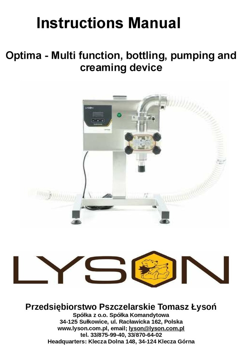
Multifunctional device for honey dosing,
creaming and pumping with a countertop
Przedsiębiorstwo Pszczelarskie Tomasz Łysoń
Spółka z o.o. Spółka Komandytowa
34-125 Sułkowice, ul. Racławicka 162, Polska
www.lyson.com.pl, email: ly[email protected]
tel.33/875-99-40 , 33/870-64-02
Company based in: Klecza Dolna 148 , 34-124 Klecza Górna

1
The following manual encompasses the
device bearing the following coding:
W204003
Manual
1. General safety operational principles for the
device
1.1. Operational principles
1.2. Electrical safety
1.3. Operational safety
2. Manual
2.1. Mode for dosing/ making up the weight
2.2. Creaming/pumping mode
2.3. Controller diagnostics
2.4. Error report
3. Setting up the controller
3.1. Setting up the controller for honey dosing
3.2. Information button
3.3. Setting up the mode for pumping/creaming
3.4. Technical data
4. Maintenance and cleaning
5. Recycling
6. Guarantee
3.4.1 Bottler socket description
3.4.2 Device components

2
1. GENERAL SAFETY OPERATIONAL
PRINCIPLES FOR THE DEVICE
Prior to operating the device please refer to the
manual and act according to the guidelines contained therein.
The manufacturer cannot be held accountable for the damages
cause by misusing the device or its improper handling
1.1. OPERATING PRINCIPLES
1. The device is intended to pour honey into the jars.
2. Prior to operations, the device must be washed thoroughly
with hot water containing slight amount of detergents permitted
to clean the device contacting food products
1.2. ELECTRICAL SAFETY
The device must be connected to the socket , having the
voltage specified on the product nominal plate. Electric
installation must be equipped with RCD having the
nominal activation current below 30 mA. The operation
of the over-current circuit breaker must be checked
periodically .
Regularly check the supply cable. If a supply cable
gets damaged, they must be replaced. In order to avoid
the threat, it must be performed by a guarantor or by a
specialised servicing centre or by an authorised person.
Do not operate the device when a supply cable is
damaged .
Check the power supply cable periodically. If the supply
cable gets damaged it must be replaced with the cable of
the same type.
Do not operate the device when the supply cable is
damaged.
Shortcut at the outlets of the controller may lead to the
device being damaged.
1.3. OPERATIONAL SAFETY
a) The following equipment is not intended to be used
by persons with limited physical, sensory or mental
capabilities (including children) or persons
inexperienced or unfamiliar with that type of
equipment unless the usage occurs under
supervision or in line with the equipment operating
manual provided by safety supervising persons.
b) Make sure the children do not play with the device.
c) In order to avoid the threat, it must be performed by
a guarantor or by a specialised servicing centre or by
an authorised person .
d) Do not operate the device in the vicinity of flammable
materials.
e) It is forbidden to make any maintenance works while
device is under operation.
f) In case of any threat, switch off the device
immediately.
g) The device can be restarted once the threat has
been eliminated
h) The device may be activated indoors only. It has not
been adjusted to be operated outdoors.
i) Protect the controller against the humidity (also
Turing the storage)
j) It is forbidden to pull the power supply cable.
k) The power supply cable must be kept away from the
heat sources, Sharp edges and its good technical
conditions must be taken care of.
2. MANUAL
ATTENTION!
HONEY INTENDED FOR DOSING MUST BE HEATED
TO THE TEMPERATURE OF 30°C.
PRIOR TO STARTING THE WORK WITH A DOSING
DEVICE, THE ROTOR MUST BE SUBMERGED IN
HONEY
2.1. THE MODE FOR DOSING / MAKING UP THE
WEIGHT
FM-02 controller is a device to control the operation of
the dosing pump as well as the creaming cycle. The
device is fully programmable and makes it possible to set
up the dosing sequence precisely. Device handling is
meliorated by an interactive, intuitive screen menu.
Fig.1. Controller handling screen –selected
dosing/making up the weight mode

3
Button
Function
„plus” button
Increasing the value of a selected
parameter.
„minus” button
Decreasing the value of a selected
parameter.
Button„ arrow
up”
Shifting between the changeable
parameters – setting a cursor on a
parameter subject to modification.
Button „arrow
down”
Button „i”
Displaying an aid to illustrate the
function of a currently selected
parameter to be modified. The button
remains active in a stop mode.
Button „…”
Changing the operational mode dosing
<-> creaming / pumping. The button
remains active in a stop mode.
Button „STOP”
Stopping the dosing cycle.
Button „ma king
up the weight” –
1g
Single-time adding the minimum doze.
Holding the button pressed will add 1 g
of weight and subsequently will activate
the mode of permanent weight making
up – it lasts until the button is released
Basic parameters of the mode
Programming of the controller dosing mode is made by
modifying the set of parameters to configure the dosing
process. The parameters modified influence directly the
shape of the dosing curve – demonstrated in fig 2 and 3.
All modified parameters have been grouped – the groups
have the common letter index.
PARA
METR
E
FUNCTION
m1
Parameter to regulate the quantity of pumped
agent in one dosing cycle. The range
of changes is 45-45000[g]. Set-up raster
equals 1[g]. The value displayed equals the
mass of the agent subject to dosing –
calibrated for a precise density and
temperature of the agent pumped. The
parameter setting does not disappear
once the power supply is switched off.
v1
The parameter to regulate the speed of the
agent dosing. The range o changes is 50[%]
– 100[%]. Change raster equals 10[%]. The
parameter setting does not disappear once
the power supply is switched off.
t1
The parameter to regulate the speed of
reverse motion – cutting off the leakage of the
dosing agent . The range of changes
between 10-900[ms]. The setting raster
equals 10[ms]. Parameter setting does not
disappear once the power supply is switched
off.
V2
The parameter to regulate the pump
operating speed while making up the weight
of agent (single-time weight making up by
1[g]). With maintained constant operating
time towards pumping, change of speed
causes the change in the quantity of the
agent made up. Increasing the speed shall
increase the quantity dosed. The range of
changes is 40[%] – 100[%]. Setting raster is
5[%]. Parameter setting does not disappear
after power supply is switched off.
Fig 2. The course of dosing process for the
predetermined mass m1.
Dozowanie
prędkość = v1
masa = m1
kierunek (+)
prędkość
czas
Odsysanie
czas = t1
kierunek (-)
v1
t1
m1
Kierunek
pompowania
Kierunek
odsysania

4
Fig 3. The course of the weight ma king up process for
the mass 1[g]
Additional parameters of the mode
PAR
AME
TER
FUNCTION
p1
The counter of dosing cycles counting up. It is
possibile to enter any value as the basis for
calculations. The range of the counter reading
0-999
p2
The parameter for filling up progress. The
value displayed shows the percentage of
filling-up process completion with relation to
the value pre-set by parameter m1. Readings
change within the range 0[%] to 100[%].
Reading raster is 1[%].
p3
Positive correcting factor. It allows to increase
precisely the mass m1 to be dosed – in case
when the mass to be dosed is below the pre-
set value and the change raster 10 g is too big
to set up the dose precisely. Increasing the
value f the factor increases the quantity of the
agent to be dosed. Possible range of setting
0-50. The factor does not refer to the current
mass setting, i.e. adds the same value (mass)
to the setting 50[g] as to the setting 1500[g].
The parameter setting does not disappear
once the power supply is switched off.
p4
Negative correcting factor. It allows to
decrease precisely the mass m1 to be dosed
– in case when the mass to be dosed is below
the pre-set value and the change raster 10 g
is too big to set up the dose precisely.
Increasing the value f the factor decreases the
quantity of the agent to be dosed. Possible
range of setting 0-50. The factor does not
refer to the current mass setting, i.e. adds the
same value (mass) to the setting 50[g] as to
the setting 1500[g]. The parameter setting
does not disappear once the power supply is
switched off
.
2.2. CREAMING /PUMPING MODE
The creaming process by means of a dosing device is
based on pumping honey inside one container. The
process involves a regular honey pumping for several
days until the proper consistence has been achieved.
Fig4. Controller handling screen –selected mode
creaming/pumping
FIELD FUNCTION
1 Pump operating status (START / STOP).
2 Pumping speed (50% … 100%).
3 Indication of time that has passed since
the pump was activated. Changing the
timer setting zeros the indication
4 Indication of time after which the pump
will be stopped automatically.
BUTTON FUNCTION
Button
„plus”
(upper)
Increasing the creaming/pumping
Speer. The range of settings 50% …
100%.
Dozowanie
prędkość = v2
kierunek (+)
prędkość
czas
Odsysanie
kierunek (-)
v2
Kierunek
pompowania
Kierunek
odsysania
Button
„minus”
Decreasing the creaming/pumping
speed. The range of setting 50% …
100%.
Button
„plus”
(upper)
Increasing the time on the timer, after
which the pump will be stopped
automatically. The indication 00:00:00
will deactivate the function of automatic
pump operating time stoppage. Setting
may be changed in the start mode.

5
Button
„minus”
Decreasing the time on the timer, after
which the pump will be stopped
automatically. The indication 00:00:00
will deactivate the function of automatic
pump operating time stoppage. Setting
may be changed in the start mode.
Button
„i”
Displaying the help – active in the stop
status.
Button
„…”
Changing the operating mode <->
creaming/pumping. Button active in
stop status.
Button
„STOP”
Stopping the pumping.
Button
„START” Pumping activation.
2.3. CONTROLLER DIAGNOSTICS
FM-02 controller has been equipped with
advanced diagnostics procedures – allowing to make
tests. In order to enter the diagnostic mode, Press
button no 5 during the proper chase of the controller
start-up (see picture below)
Fig 5. Controller view during start-upButton numbers
Diagnostic screen is divided into 14 sections, their
functions, see below. Leaving the diagnostic screen,
diagnostic goes automatically after 25 s.
Fig 6. Screen –controller diagnostic.
Secti
o
n
descripti
onIndication
Funkcja
1 CPU 1E9705
Displaying the
value other than
1E9705
Indicates the
Damages of the
main processor.
2 EEPROM OK /
ERROR
f ERROR notice m
Multiple, repetitive
(despite controller
restarting)
appearance o the
damages of EEprom
memory
cell/cells in the
controller
3 Vcpu [V] 4,60 – 5,40
Measurement of
the power supply
voltage for the
CPU module of the
controller.
Indication outside
the range means
damage/
overloading
of the feeder or
CPU module
damage.
1
2
3
4
5
6
7
8

6
4
Vbus [V]
4,30 – 5,70
Measurement of
the voltage on
the connection of
the data
transmission to
the inverter.
Indication
outsider the
range means the
inverter fault or a
gap in the
connection
controller <>
inverter
5
TEMP [oC]
5 - 65
Measuremen
t of the
temperature
inside the
controller
cabinet. The
values
should not
exceed the
given range.
6
IN1 IN2
0 / 1 0 / 1
Testing the
dosing start
input (IN1)
and the
emergency
button input
(IN2)
7
PB1
0 / 1
Testing the
operations of
button 1.
8
PB2
0 / 1
Testing the
operations of
button 2.
9
PB3
0 / 1
Testing the
operations of
button 3.
10
PB4
0 / 1
Testing the
operations of
button 4.
11
PB5
0 / 1
Testing the
operations of
button 5.
Testing the
operations of
button 6.
13 PB7 0 / 1
Testing the
operations of
button 7.
14 PB8 0 / 1
Testing the
operations of
button 8.
2.4. ERROR REPORT
FM-02 controller has been equipped with advanced
error detection mechanisms. Detecting any error
activates the action of emergency motor stoppage and
triggers the error report screen. It is displayed
permanently So it is necessary to switch off the power
supply, remove the error source and controller restarting
Fig. 7. Controller error report screen.
sect
ion
Descrip
tion
Indicati
on ERROR DESCRIPTION
1 CPU OK /
ERROR
Indication ERROR means the
error of the controller’s main
processor data memory. Most
frequent reason for this fault to
occur is the damage due to
electrostatic discharges.
12 PB6 0 / 1

7
2
RAM
OK /
ERROR
Indication ERROR signals the
error detection with regards to
controller’s RAM memory data
cohesion. The situation is
possible in case when the
controller operates within the
environment with high level of
background noise. This may
be brought about by: damaged
cable connections, damaged
inverter, damaged inverter
casing. Another reasons may
include: damaging of the main
processor module caused by
electrostatic discharges.
3
Vcpu [V]
OK /
ERROR
Indication ERROR means that
the measured controller
module power supply voltage
is outside the permissible
range. The said situation
means the fault or
overloading of 5V feeder,
failure of the controller or
damage to the cable
connection feeder <>
controller.
4
Vbus [V]
OK /
ERROR
Indication ERROR means that
the voltage measured on the
data transmission connection
to the inverter is outside the
permissible range. The
situation means the failure of
inverter, failure of the
controller or a gap in the cable
connection inverter<>
controller.
5
TEMP
[oC]
OK /
ERROR
Indication ERROR means that
the temperature measured
inside the controller casing is
outside the permissible range
5 oC do 65 oC. This may be
caused by inverter overloading
or using the extractor in the
temperatures outside the
permissible range.
6
STATUS
OK / ----
7
PB1
OK /
ERROR
Indication ERROR means that
button pressing has been
detected – directly after power
supply activation. If the
situation has not been
intentional, the button might be
damaged. – e.g. pressing and
button blockage due to
excessive force having been
applied.
8
PB1
OK /
ERROR
Description – as above.
9
PB1
OK /
ERROR
Description – as above.
10 PB1 OK /
ERROR
Description – as above.
11 PB1 OK /
ERROR
Description – as above.
12 PB1 OK /
ERROR
Description – as above.
13 PB1 OK /
ERROR
Description – as above.
14 PB1 OK /
ERROR
Description – as above.
3. CONTROLLER SETTING
ATTENTION!
HONEY INTENDED FOR DOSING MUST BE
HEATED UP TILL THE TEMPERATURE OF 30 °C.

8
PRIOR TO STARTING WORK, THE ROTOR MUST
BE SUBMERGED IN HONEY.
There are two ways to submerge the rotor in honey:
First way:
1. Connect the duct to the dosing device rotor by
means of a clamp, watch for the proper
positioning of the gasket.
2. Next, pour approximately 1 kg oh honey by the
other end of the duct.
3. Keep the duct upwards until the honey has
drained to the rotor (dosing device)
4. The duct is transparent so one can see when the
honey has reached the rotor,
5. When the honey has reached the rotor, put the
hose in the honey tank, press and hold button
no 8 until the honey has been sucked in
6. As soon as the hose is totally filled with honey,
release button no 8 – the dosing device will stop.
Second way:
1. The rotor must be poured with honey by means
of a syringe for cakes with the tip having the
biggest orifice.
2. Assemble the hose watching for proper
positioning of the gasket. The other end of the
hose shall be placed inside the honey tank and
press and hold button number 8 until the honey
has been sucked in.
3. One should flow slight amount of honey to
remove the air that stayed inside the hose, owing
to which we will avoid the jars being filled
unevenly.
4. It must be remembered to put a jar for honey
under the dosing device nozzle.
5. When the hose is entirely filled with honey,
release button number 8 – the dosing device will
come to a hold.
6. Having completed the said activities, move to
dosing device setting.
3.1. SETTING THE CONTROLLER FOR HONEY
DOSING.
Once the controller has got activated, the interactive
panel will be displayed, by which we can set up
individual parameters needed to programme the
controller. Once connected to the mains, the dosing
device displays the parameters to be set by means of
buttons „plus” (no 1), „minus” (no 2)
Photo 2 Decreasing the value of a given parameter In
order to shift between the parameters, press the
button arrow „up”(no.3) or arrow „down” (no.4).
Photo. 3 Selecting the parameter by means of the
buttons arrow „up” and „down”(shifting between the
parameters)
Photo. 4 Selecting the parameter (shifting between the
parameters)
Photo. 1 Increasing the value of a given parameter

9
>After getting connected to the mains, the controller is
ready for the changes in parameters to be
introduced.
>After setting is completed, the dosing device
remembers the parameters set automatically.
DESCRIPTION OF PARAMETERS
–m1 parameter serves to set the weight (grams of
honey to be dosed by the device)
Range of changes: 45-45000[g]
Parameter setting does not disappear after power supply
deactivation.
–v1 speed of honey pouring – e.g. 100%. If honey is
pumped too quickly and gets aerated excessively,
reduce the filling speed to, e.g. ,70%
Range of changes: 50[%] –100[%].
Parameter setting does not disappear after power supply
deactivation.
–t1 withdrawing time specified in MS. This parameter
ought to be set u after the first attempt to pour honey
into jars. Then , it is easy to determine whether the
dosing device withdraws honey quickly enough to
avoid dripping.
Range of changes: to 10-900[ms]
Parameter setting does not disappear after power
supply deactivation.
–v2 Parameter serving to regulate the dosing device in
order for it to make up the weight of 1 g of honey.
The regulation boils down to setting up the rotational
speed of the rotor with relation to the honey density,
viscosity and temperature.
Parameter setting does not disappear after power supply
deactivation.
Place a jar on the scales and tare the scales, press
button number 8 (i.e. making up the weight) and check
the result on the scales, whether is shows 1 g.
(manual option used during filling the jars by means of
button number 8 or a pedal)
Range of changes: 40[%] –100[%]
Photo . 5 Button for making up the weight or pump
permanent operations (pressing and holding makes the
pump work permanently)
- p1 no necessity to setting.
One may use the parameter by setting up the number of
the jars filled in on the previous day in order to provide
continuity of counting.
Range of counter indications: 0-999.
–p2 not to be set, the parameter displays the degree
of jar filling in %
–p3 Positive weight calibration (1g)
Serves to calibrate (increasing) of the parameter m1.
When the weight m1= 500 g and is not sufficient and
after filling the indication shows 495 g and the parameter
m1 cannot be set, then correction may entered by means
of the parameter p3.
Set parameter p3 as 5 (i.e. the missing 5 g), which
increases the weight m1 by 5. After activation, the
controller sums up the parameter m1+p3 and doses 500
g of honey to a jar.
Range of changes 0-50
Parameter setting does not disappear once disconnected
from the mains.
-p4 - Negative weight calibration (1g)
Serves to calibrate (decrease) m1 parameter.
When the weight m1 = 500 g and is not sufficient and
after jar filling the scales indicates 505 g and it is
impossible to set m1 parameter precisely, then a
correction must be made by means of p4 parameter.
Set p4 parameter as 5 (i.e. excessive 5 g), which will
decrease weight m1 by 5. Once activated, the controller
sums up weight setting m1+p4 and measures 500 g of
honey t a jar.
Range of changes 0-20
Parameter setting does not disappear once disconnected
from the mains.
3.2. INFORMATION BUTTON
It gives a possibility to display graphic information about
a given parameter. Pressing the button activates the
graphics and pressing the button “i” (number 5) again
deactivates graphic displays.
This parameter is a form of a hint showing what a given
parameter refers to.

10
Photo. 6 Information button
3.3 SETTING UP PUMPING/CREAMING MODE
Honey creaming mode is based on pumping the honey,
i.e. starting the pump in a continuous mode. Controller
makes it possible to set the time for pumping/creaming.
Photo. 7 Entering the pumping/creaming modeHaving
pressed button number 6, a panel for continuous
pumping/creaming or pumping for a pre-set time , min
15 s – max 90 hours, is displayed.
Photo. 10 Deactivation of pumping mode , button
number 7 (STOP)
-SETTING UP THE PUMP FOR A SPECIFIED TIME
AND SPEED
- in order to set up pumping for a specified time, e.g. 20
min, activate pumping/creaming mode (button no 6)
- Press Start button (no 8)
- When pumping is activated, by means of lower buttons
„plus” (no 3) or „minus” (no 4) set the operating time
for the pump. Once the time is programmed, the timer
will start counting since the beginning, it will switch off
automatically after the pre-set time.
Photo 11 By means of the Lower button„plus” (no 3)
or „minus” (no 4) set up the pump operating time.
Setting up the pumping/creaming time „plus”(no 3) or
„minus” (no 4).
By means of this parameter, honey pumping/creaming
speed can be changed. Changing the setting possible
during pump operation „START” or in a „STOP” mode
Range of changes 50% … 100%.
Photo. 8 Control panel after pumping/creaming
option has been activated.
Photo. 9 Activation of pumping mode - button number
8 START Pump starts continuous operations until STOP
button is pressed
CAUTION!
Before starting the process of honey creaming or
pumping, remove the dosing nozzle immediately!!!

11
4. MAINTENANCE AND CLEANING
–Power supply 230 V
–Power 200 W
–Filling range 45 g – 45000 g
–Fills up approximately 350 jars a 500 g/hour
(depending on the type and density of the honey).
–Filling accuracy +/- 1 g until the capacity of 1200
g , over 1200 g, accuracy +/- 1,5%
–All parts coming in contact with honey are made
of stainless steel, plastics permitted to come into
contact with food products.
–Small dimensions allow to place the device in
different arrangements, even with limited surface.
–Pump efficiency 250 - 300 L of honey/hour
Photo 12Upper button „plus” (no 1) or „minus”
(no2) serves to increase or decrease the pumping/
creaming speed
3.4 TECHNICAL DATA
3.4.1 BOTTLER SOCKET DESCRIPTION
nr.1
nr.2
nr.3
nr.4
No.1 - power supply socket 230VAC
No.2 - communication socket ( foot pedal switch, fill
switch)
No.3 - main power switch
No.4 - fuse socket
3.4.2 DEVICE COMPONENT
- honey bottler
- bottler's table top
- foot pedal switch
- fill switch
- hose clamp ∅40
- hose ∅40 - 1,5mb
PRIOR TO THE MAINTENANCE, DISCONENCT FROM
THE MAINS!
The dosing device shall be washed thoroughly before
and after the usage. While washing be careful not to
damp the motor and controller (they may be covered
with water-resistant materials).
Dry the device after washing. Before every season,
additional technical inspection must be performed. In
case any defect is
Clean the device in two phases: preliminary and final
(disinfecting).
Preliminary phase – rinsing out the honey from the
nozzle and dosing module. Do not dismantle the
dispenser after the bottling process is finished.
Immediately after working with the device, place the
suction hose into a container with warm water and pump
40 l of warm water to rinse out the pump or dosing
module.
For this operation, prepare approx. 40 l of water heated
up to 50°C – 60°C. This process protects the dispenser
from damage that may be caused by crystallised honey
(i.e.: breaking the seal and leaking honey). If the unit is
improperly rinsed, the seal on the pump module shaft will
break. Damage resulting from improper cleaning of the
module is not subject to warranty.
Disinfecting final phase – dismantle the nozzle and
rotor as shown in the photographs below. Thoroughly
wash, dry and assembly together again.
For cleaning use agents designated for disinfection of the
equipment intended for contact with food, then rinse
thoroughly, dry and re-assemble.
Step 1
Unscrew the rotor cover bolts.

5. RECYCLING
Worn-out product must be removed as waste only
within selective waste collection organised by the
Network of Communal Electric and Electronic
Waste Collecting Points. A customer is entitled
to return the used equipment to the electrical
equipment distributor network, at least free of charge
and directly, if the device to be returned is of proper
type and serves the same purpose as the newly
purchased device
6. Guarantee
Products purchased from “Łysoń’ company are
encompassed by the manufacturer’s guarantee.
The guarantee duration equals 24 months
A receipt or a VAT invoice is issued for each product
purchased
Details on the guarantee, see www.lyson.com.pl
Step 2
Remove the cover.
Step 3
Remove the set ring
Step 4
Remove the dispensing nozzle
Step 5
Remove the pumping module
Table of contents
Other LYSON Commercial Food Equipment manuals
Popular Commercial Food Equipment manuals by other brands

Hussmann
Hussmann Q1-SSN Installation & operation guide

Buffalo
Buffalo CJ558 instruction manual

Roller Grill
Roller Grill FM2 Use and installation manual

Perlick
Perlick TOBIN ELLIS SIGNATURE Series Installation & operation manual

Viessmann
Viessmann Tecto SV5 installation guide

Wisco Industries
Wisco Industries 695D manual

turbofan
turbofan 30D Series Service manual

FORGE ADOUR
FORGE ADOUR CHPAF manual

Counterline
Counterline Integrale Operation & maintenance manual

Braun
Braun Aesculap Instructions for use and Technical description

Silver King
Silver King SKRCB38H-EDUS Technical manual and replacement parts list

RoboLabs
RoboLabs CKPMX-03M2 user manual