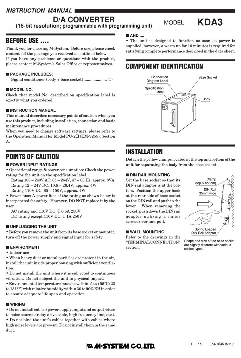
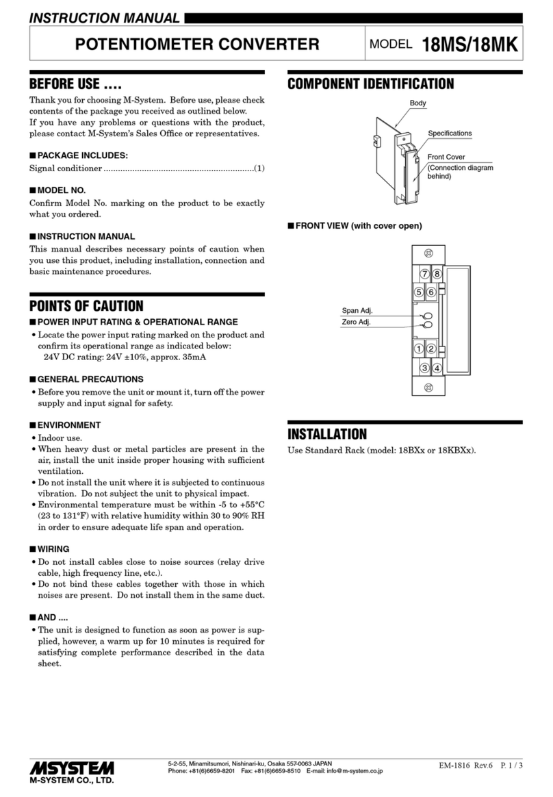
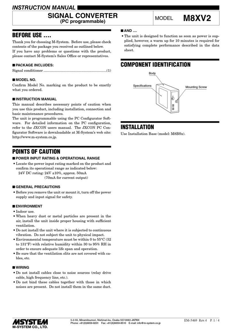
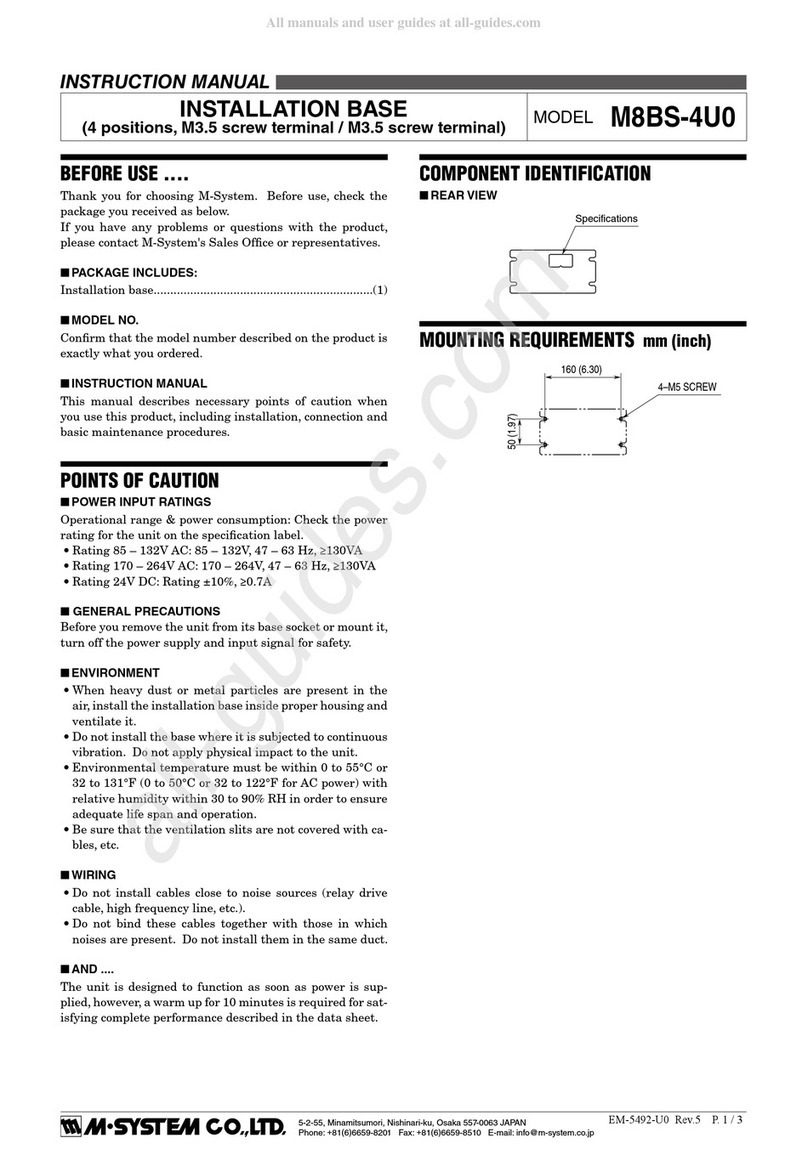
M-system JAPD User manual

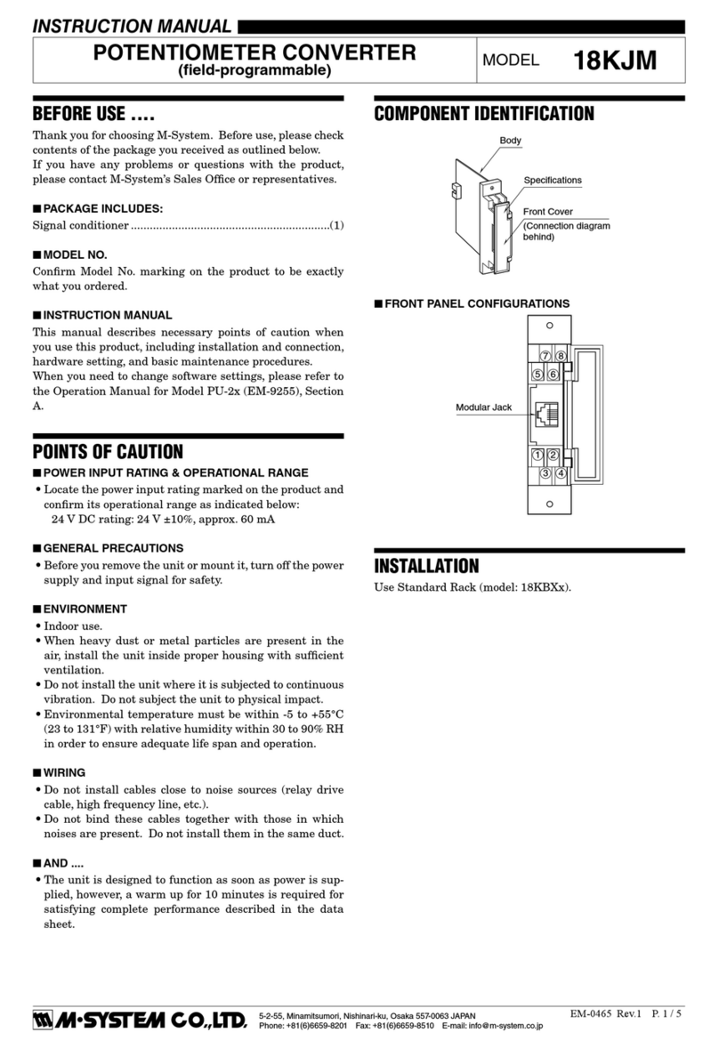
JAPD
EM-1687 Rev.1
P. 1 / 5
BEFORE USE ....
ThankyouforchoosingM-System. Beforeuse,checkthepackage
you received as below.
If you have any problems or questions with the product, please
contact M-System's Sales Office or representatives.
■ PACKAGE INCLUDES:
Signal conditioner (body + base socket + input resistor) (1)
Input resistor is provided only with current input type.
Ordering Information Sheet (1)
Not included when the unit is shipped with default settings.
■ MODEL NO.
Check that model No. described on specification label is exactly
what you ordered.
■ INSTRUCTION MANUAL
This manual describes necessary points of caution when you use
this product, installation and connection, hardware setting, and
basic maintenance procedures.
When you need to change software settings, please refer to the
Operation Manual for Model PU-2❑(EM-9255), Section B.
ThisunitisfactoryadjustedandcalibratedaccordingtotheOrdering
Information included in the product package. If you don't need to
change the pre-adjusted setting, you can skip the sections on
hardware setting and calibration in this manual and the Operation
Manual for Model PU-2❑.
FUNCTION & FEATURES
• Providing a pulse rate output in proportion to DC input signal
• Micro-processor based
• Parameters are field-programmable via hand-held programmer
PU-2❑
• Input signal and parameters can be monitored with the PU-2❑
during operation
• Duty cycle of the output pulse: 50%
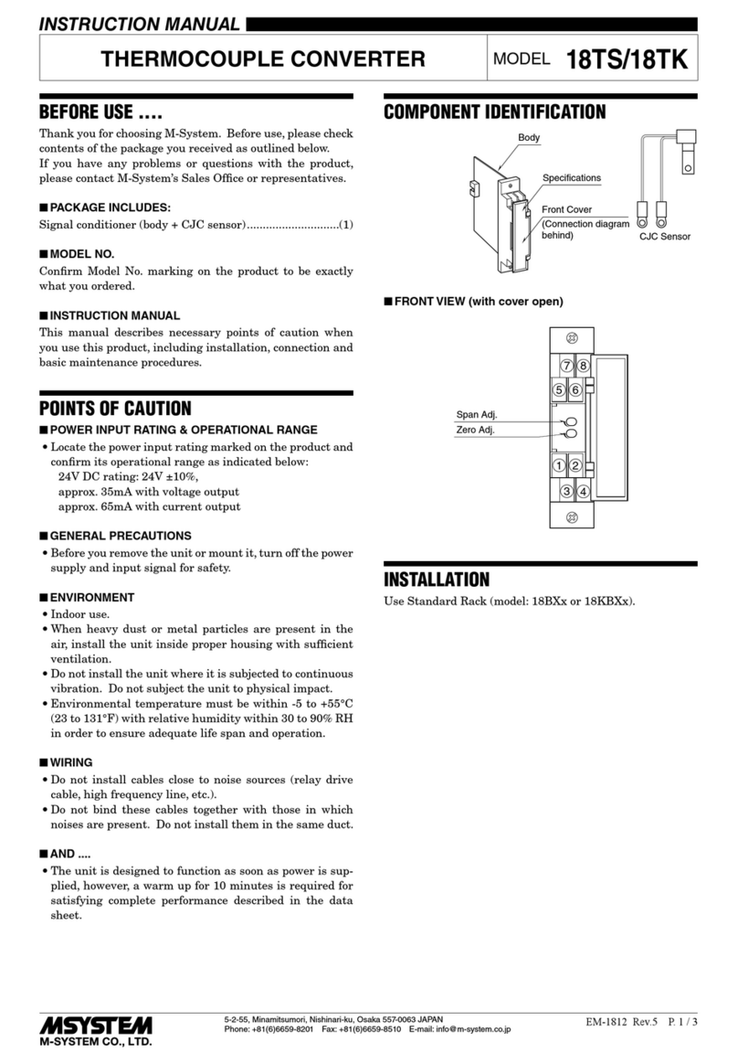
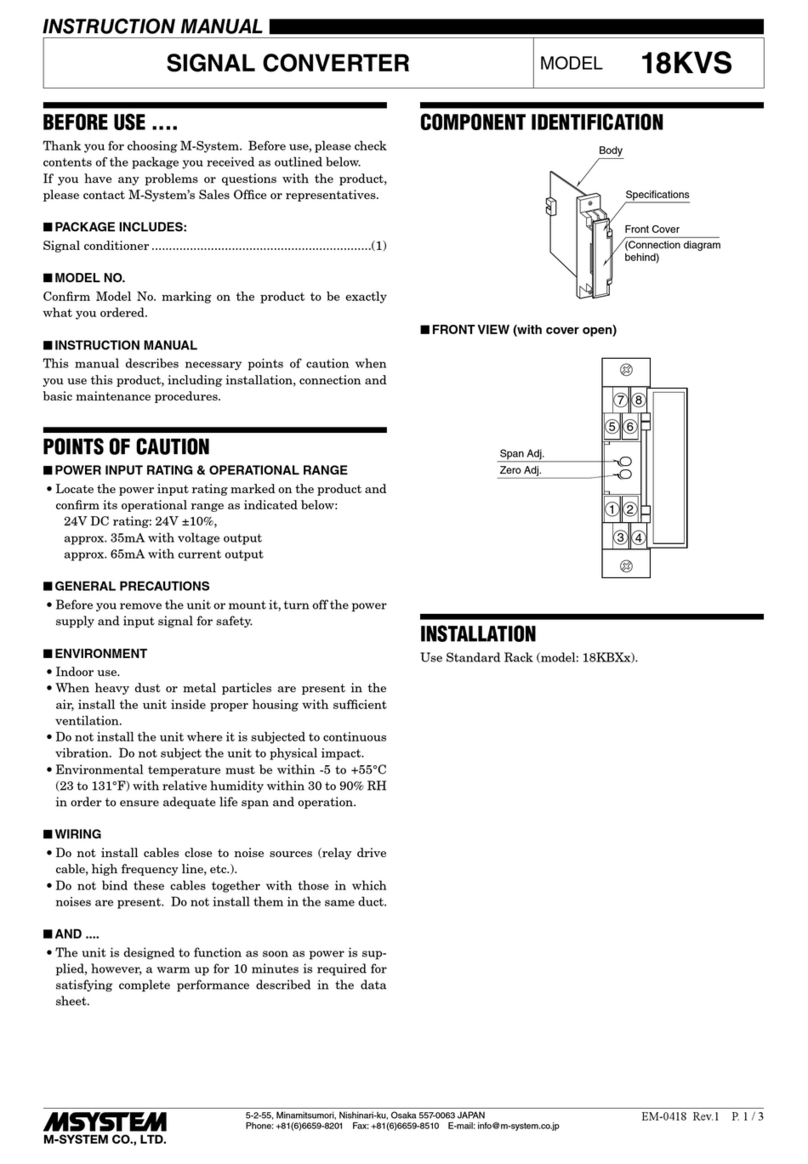
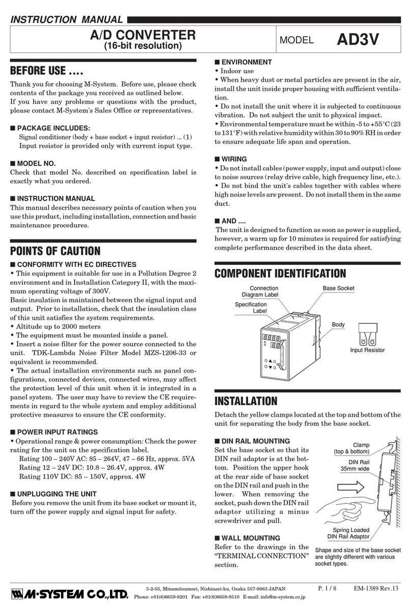
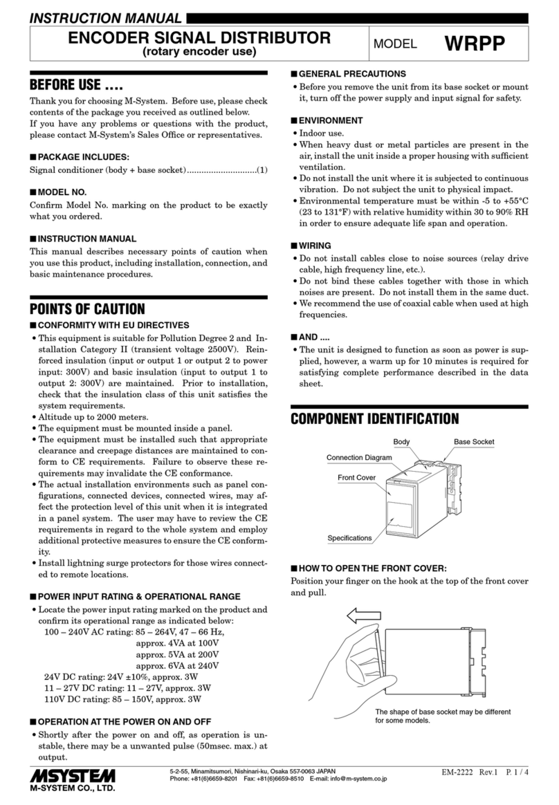
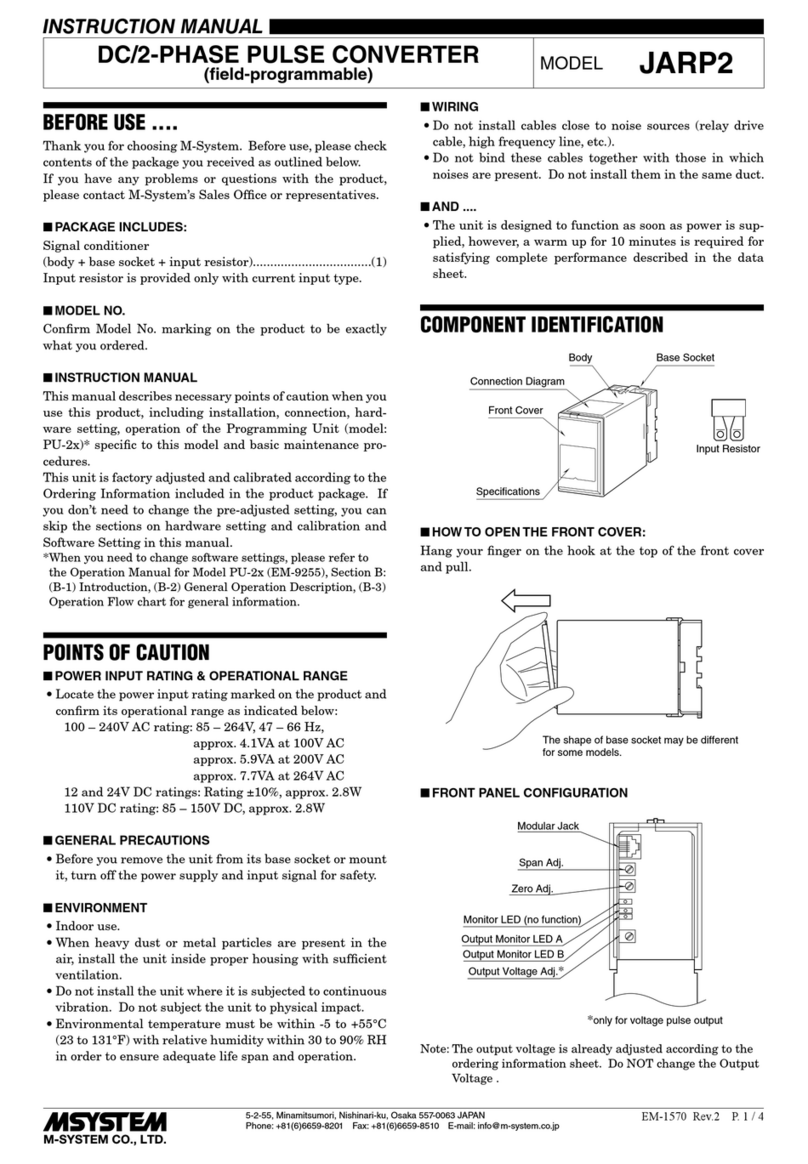
COMPONENT IDENTIFICATION
■ HOW TO OPEN THE FRONT COVER:
Position your finger on the hook at the top of front cover and pull.
The shape of base socket may be different
for some models.
■ FRONT PANEL CONFIGURATION
INSTRUCTION MANUAL
MODEL JAPD
Body Base Socket
Connection
Diagram Label
Front Cover
Specification
Label
Input Resistor
Front Cover (open)
Output Voltage Adj.
Output Monitor LED
Modular Jack
Zero Adj.
Span Adj.
Status Indicator Monitor LED (not used)
DC/FREQUENCY CONVERTER
(field-programmable)
DO NOT TOUCH it for RS-
422 line driver output.
The output voltage is already
adjusted at the factory and
paint-locked.

JAPD
EM-1687 Rev.1
P. 2 / 5
INSTALLATION
Detach the yellow clamps located at the top and bottom of the unit
for separating the body from the base socket.
■ DIN RAIL MOUNTING
SetthebasesocketsothatitsDIN
railadaptorisatthebottom. Posi-
tiontheupperhookattherearside
ofbasesocketonthe DIN rail and
push in the lower. When remov-
ingthesocket,pushdowntheDIN
railadaptorutilizingascrewdriver
(–) and pull.
■ WALL MOUNTING
Refer to the drawings below.
TERMINAL CONNECTIONS
Connect the unit as in the diagram in the next page or refer to the connection diagram label on top of the unit.
When an input resistor is provided with the module, attach it together with input wiring to the input screw terminals.
3456
2187
80 (3.15)
50 (1.97) 107 (4.21)
127 (5) [3.3 (.13)]
80 (3.15)
20
(.79)
35.4 (1.39)
40 (1.57)
50 (1.97)
7.8 (.31)
CLAMP
(top & bottom)
DIN RAIL
35mm wide
2–4.5 (.18) dia.
MTG HOLE
15 (.59) deep
8–M3.5
SCREW
•When mounting, no extra space is needed between units.
56
2187
34
12 (.47)
INPUT RESISTOR
(model: REM)
Input shunt resistor attached
for current input.
■ TERMINAL ASSIGNMENT mm (inch)
■ DIMENSIONS mm (inch)
Clamp
(top & bottom)
DIN Rail
35mm wide
Spring Loaded
DIN Rail Adaptor
Shape and size of the base socket
are slightly different with various
socket types.
■ CONNECTION DIAGRAM
+
–
*
*Input shunt resistor attached for current input.
INPUT 3
R4
5
6
+
–
1
2
U(+)
V(–) POWER
7
8
OUTPUT
PU-2❑
MODULAR JACK
–
+
ALARM OUTPUT
■Open Collector
Output Connection Examples
+
–
1
2
+
–
■Voltage Pulse
+
–
1
2
+
–
2kΩ
5 – 12V
+
–
■RS-422 Line Driver Pulse
+
–
+
–
1

JAPD
EM-1687 Rev.1
P. 3 / 5
operating the Programming Unit.
In MONITOR mode (Maintenance Switch = 0), the unit is in normal
operation: repeating measuring, calculating and renewing the out-
put signal. In this status, the status indicator LED is flashing in
constant intervals of approx. 3 Hz (ON : OFF = 1 : 1). You can
monitorinput%,output%andoperatingstatus,variousparameters,
etc. on the Programming Unit.
The PROGRAM mode (Maintenance Switch = 1) is used when you
change various parameters concerning measuring, calculation and
output. Inthisstatus,thestatusindicatorLEDisflashinginconstant
intervalsofapprox.1.5Hz(ON:OFF=1:1). Inthetransitionperiod
fromMONITORtoPROGRAMmode,theLEDflashesapprox.in1.5
Hz but in different intervals (ON : OFF = 1 : 3), which indicates that
the unit is still processing the last cycle of measuring.
In PROGRAM mode, the unit stops measuring and renewing the
outputsignal. Theoutputisheld,butyoucanoutputaspecificvalue
for simulation and testing.
Whenalltheprogramchangeisover,be suretoreturn thetransmit-
ter to MONITOR mode. The modification will be lost if you turn off
power supply to the transmitter without doing this.
EXPLANATIONS OF TERMS & FUNCTIONS
■ BASIC OPERATION
After the power is turned on, the JAPD accesses and checks the
data stored in its non-volatile memory. When there is no abnormal-
ity, it starts measuring.
The input signal, processed through the analog input circuit and
convertedintofrequency,iscomparedwiththepreset0%(zero)and
100%(span)inputvalues(as calibrated at the factory)todetermine
the input value. Then the signal is compared with the preset 0%
(zero)and100%(span)outputvaluesandconverted proportionally
into an frequency output.
Whenthecomparedresultisoutofthenormaloperationalrange,the
output is limited to a value -15% or +15% of the full-scale.
The input is sampled according to the sampling time (default 200
ms), and the output is renewed every this cycle.
■ OPERATION MODE AND MAINTENANCE SWITCH
There are two operation modes: MONITOR mode and PROGRAM
mode.
Whenthepowersupply is turned on, theunitstartsup in MONITOR
mode. However, you can switch from one mode to another by
■ STATUS INDICATOR LED
TheCPUstatusisindicatedbydifferentblinkingpatternsofthefront
indicator LED. 1 pattern cycle is divided in 16 ON or OFF periods,
each of which lasts for 320 millisec.
In the figure to the right, ●●means that the light is OFF, while ●
meansthatit isON. TheON-OFF pattern changesfromthe leftend
to the right in 320 millisec. duration.
There are more of these patterns which are not shown here,
however, when the last one shown in the figure to the right or some
other pattern is indicated, contact M-System.
The anomaly report is available also on the display of the Program-
ming Unit. Refer to its manual for detailed information.
MONITOR MODE
Measuring Processing
Monitor. Parameters
Available
Monitor. Measuring
Value Available
PROGRAM MODE
Measuring Stopped
Changing Parameters
Available
Output Simulation
Available
Maintenance Switch = 1
Maintenance Switch = 0
Parameters Saved
in the Nonvolatile Memory.
Power
Turned ON
FLASHING PATTERNS IN NORMAL CONDITIONS
Program mode
Monitor mode, abnormality in the analog input circuit.
Monitor mode, normal input status
FLASHING PATTERNS IN ABNORMAL CONDITIONS
Monitor mode, parameters are destroyed or functioning in default values.
Monitor mode, parameters are destroyed and impossible to recover.
JAPD
EM-1687 Rev.1
P. 4 / 5
HARDWARE SETTING & CALIBRATION
■ SENSITIVITY ADJUSTMENT
You can change the output voltage amplitude with the Output
VoltageAdjustmentwithin5–24V. Howevertheoutputcloseto24V
may be affected by line voltage variations.
• How to Change the Sensitivity
A voltmeter of class 0.5 or better accuracy is required.
1) Connect the voltmeter in parallel to the terminal 1 – 2 of base
socket.
2) Turn the Output Voltage Adjustment until the meter indicates a
desired value.
SOFTWARE SETTING
You can program various parameters with Programming Unit,
model: PU-2❑. For detailed explanations, please refer to the
Operation Manual for Model PU-2❑(EM-9255), Section B.
In the Programming Unit, specifying GROUP No. and ITEM No.
(each 2 digits) determines which item is to be changed.
GROUP 00 is for system functions: software version information,
+
–
*
*Input shunt resistor attached for current input.
INPUT
3
R
4
5
6
+
–
1
2
U(+)
V(–) POWER
7
8
OUTPUT
PU-2
❑
MODULAR JACK
–
+
ALARM OUTPUT
V
Voltmeter
error report, etc, which are common to all pulse transmitter series.
GROUP 01 includes all necessary parameters for pulse transmit-
ters. The table below indicates which items are related to this unit.
Youcanevenchangethoseparameterswhicharenotrelatedtothis
unit,however,itmaydestroysomeotherparameters. Besuretouse
only the items in the table.
ITEM
GROUP No.
ITEM No. DISPLAY CONTENTS
Model indication 01 00 JAPD
Maintenance switch 01 01 maintenance sw SwitchingtoPROGRAMmodewhichallowsparameterchange.
Tag No. 01 02 user's TAG entry User's Tag name entry and monitor
Input % monitor 01 05 measured input % Analog input in %
Output zero frequency 01 08 output zero freq Output frequency for 0%
Output span frequency 01 09 output span freq Output frequency for 100%
Frequency unit 01 11 unit frequency Frequency unit used in programming
Cutout time 01 20 drop out timer DO NOT change.
Sampling time 01 21 sampling timer Sampling time
Alarm threshold 01 24 alarm threshold Indicating and setting the threshold for alarm relay output.
Alarm hysteresis 01 25 alarm hysteresis Indicating and setting the hysteresis for alarm threshold.
Alarm mode 01 26 alarm mode Indicating and setting the alarm operation mode (Lo or Hi).

JAPD
EM-1687 Rev.1
P. 5 / 5
Checking & Maintenance
To TERMINAL CONNECTIONS (P.2)
End of Checking
Is the power supply voltage (Terminal 7 – 8) at the proper level?
All wires connected
according to the connection
diagram?
Is the output monitor LED
flashing according to the input
signal?
Is the input signal for
0 Hz output?
Is the unit in the
Monitor Mode?
Is the status indicator
LED blinking in intervals of
approx. 1.5 Hz?
Does the output amplitude
match the value described in the
Ordering Information Sheet?
To HARDWARE SETTING & CALIBRATION,
Refer to the output voltage adjustment. (P.4) To EXPLANATIONS OF TERMS & FUNCTIONS,
Refer to the status indicator LED. (P.3)
Switch the unit to
the Monitor Mode.
No
Yes
No
No No
Yes
No
No
Yes Yes
Yes
Yes
POINTS OF CAUTION
■ GENERAL
• Before you remove the unit from its base socket or mount it, turn
off the power supply and input signal for safety.
■ ENVIRONMENT
•Whenheavydustormetalparticlesarepresentintheair,installthe
unit inside proper housing and ventilate it.
•Donotinstalltheunitwhereitissubjectedtocontinuousvibration.
Do not apply physical impact to the unit.
• Environmental temperature must be within -5 to +60°C (23 to
140°F) in order to ensure adequate life span and operation.
■ WIRING
•Donotinstallcables(powersupply,inputandoutput)closetonoise
sources (relay drive cable, high frequency line, etc.).
• Do not bind these cables together with those in which noises are
present. Do not install them in the same duct.
■ AND ....
• The unit is designed to function as soon as power is supplied,
however, a warm up for 10 minutes is required for satisfying
complete performance described in the data sheet.
MAINTENANCE
■ TROUBLESHOOTING
Refer to the flow chart below.
M-SYSTEM WARRANTY
M-System warrants such new M-System product which it manufactures to be free from defects in materials and workmanship during the 36-month period following the date that such
productwasoriginallypurchasedifsuchproducthasbeenusedundernormaloperatingconditionsandproperlymaintained,M-System'ssoleliability,andpurchaser'sexclusiveremedies,
under this warranty are, at M-System's option, the repair, replacement or refund of the purchase price of any M-System product which is defective under the terms of this warranty. To
submit a claim under this warranty, the purchaser must return, at its expense, the defective M-System product to the below address together with a copy of its original sales invoice.
THIS IS THE ONLY WARRANTY APPLICABLE TO M-SYSTEM PRODUCT AND IS IN LIEU OF ALL OTHER WARRANTIES, EXPRESS OR IMPLIED, INCLUDING ANY IMPLIED
WARRANTIES OF MERCHANTABILITY OR FITNESS FOR A PARTICULAR PURPOSE. M-SYSTEM SHALL HAVE NO LIABILITY FOR CONSEQUENTIAL, INCIDENTAL OR
SPECIAL DAMAGES OF ANY KIND WHATSOEVER.
M-System Co., Ltd., 5-2-55, Minamitsumori, Nishinari-ku, Osaka 557-0063 JAPAN, Phone: (06) 6659-8201, Fax: (06) 6659-8510, E-mail: [email protected]
Table of contents
Other M-system Media Converter manuals

M-system
M-system M8TS User manual

M-system
M-system M8BS-8U1-R User manual

M-system
M-system Mini-M M2PRU User manual

M-system
M-system M8YV1 User manual

M-system
M-system 18PE User manual

M-system
M-system M8XV2 User manual

M-system
M-system M8MS User manual

M-system
M-system M8BS-8U0-R User manual

M-system
M-system 18VS User manual

M-system
M-system JAPD2 User manual

M-system
M-system JPR2 User manual

M-system
M-system M8BS-4U0 User manual

M-system
M-system AD3V User manual

M-system
M-system 15MS User manual

M-system
M-system 18KVS User manual

M-system
M-system JARP2 User manual

M-system
M-system M8XR2 User manual

M-system
M-system 17MS User manual

M-system
M-system M8CT User manual

M-system
M-system M8YV User manual