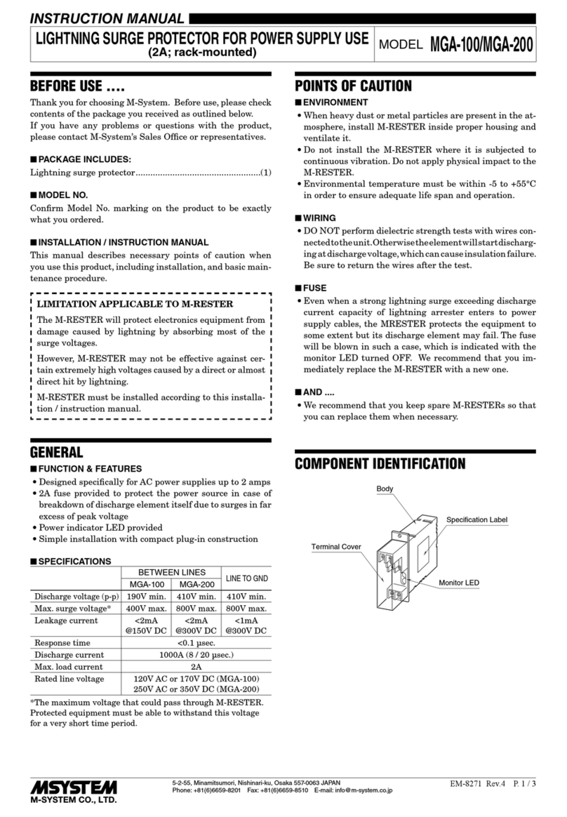
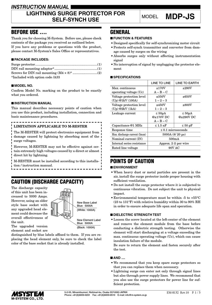
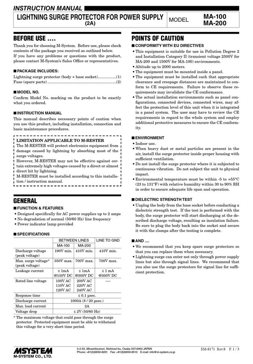
manuals.online logo
Brands
  1. Home
  2. •
  3. Brands
  4. •
  5. M-system
  6. •
  7. Surge Protector
  8. •
  9. M-system MDPA-24 User manual

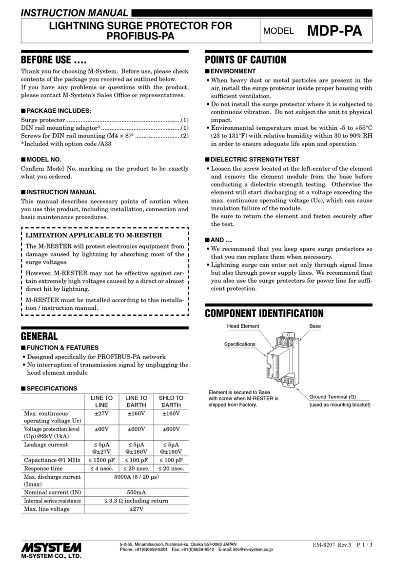
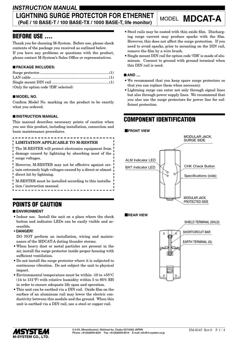
M-system MDPA-24 User manual

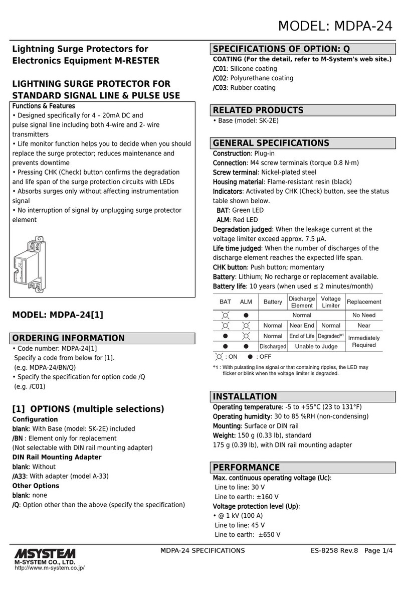
MODEL: MDPA-24
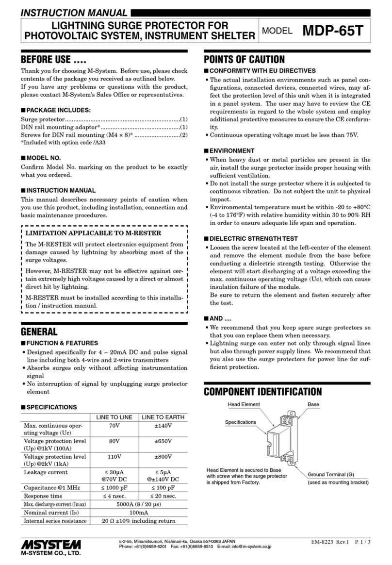
http://www.m-system.co.jp/ MDPA-24 SPECIFICATIONS ES-8258 Rev.5 Page 1/4
Lightning Surge Protectors for Electronics Equipment M-RESTER
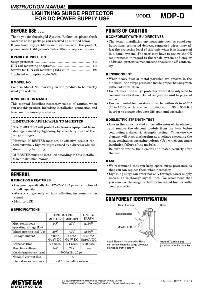
LIGHTNING SURGE PROTECTOR
FOR STANDARD SIGNAL LINE & PULSE USE
Functions & Features
• Designed specifically for 4 – 20mA DC and
pulse signal line including both 4-wire and 2- wire
transmitters
• Life monitor function helps you to decide when you should
replace the surge protector; reduces maintenance and
prevents downtime
• Pressing CHK (Check) button confirms the degradation
and life span of the surge protection circuits with LEDs
• Absorbs surges only without affecting instrumentation
signal
• No interruption of signal by unplugging surge protector
element
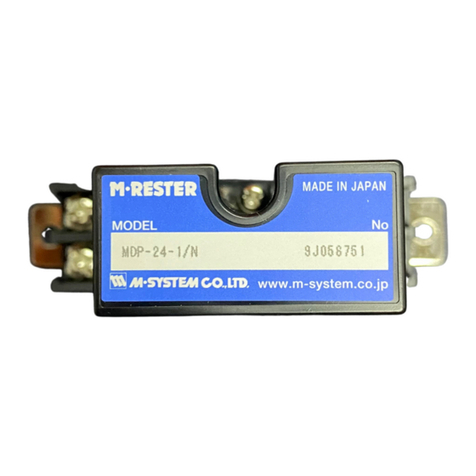
M·RESTER
MADE IN JAPAN
SER.NO
BAT
ALM
MODEL
MODEL: MDPA–24[1]
ORDERING INFORMATION
• Code number: MDPA-24[1]
Specify a code from below for [1].
(e.g. MDPA-24/BN)
[1] OPTIONS
Configuration
blank: With Base (model: SK-2E) included
/BN : Element only for replacement
(Not selectable with DIN rail mounting adapter)
DIN rail mounting adapter
blank: Without
/A33: With adapter (model A-33)
RELATED PRODUCTS
• Base (model: SK-2E)
GENERAL SPECIFICATIONS
Construction: Plug-in
Connection: M4 screw terminals (torque 0.8 N·m)
Screw terminal: Nickel-plated steel
Housing material: Flame-resistant resin (black)
Indicators: Activated by CHK (Check) button, see the status
table shown below.
BAT: Green LED
ALM: Red LED
Degradation judged: When the leakage current at the
voltage limiter exceed approx. 7.5 μA.
Life time judged: When the number of discharges of the
discharge element reaches the expected life span.
CHK button: Push button; momentary
Battery: Lithium; No recharge or replacement available.
Battery life: 10 years (when used ≤ 2 minutes/month)
Normal
: ON
*1. With pulsating line signal or that containing ripples, the LED may
flicker or blink when the voltage limiter is degraded.
: OFF
Normal
Discharged
Normal
Near End
End of Life
Unable to Judge
Normal
Degraded*
1
No Need
Near
BatteryALMBAT Discharge
Element Voltage
Limiter Replacement
Immediately
Required
Discharge element status table
INSTALLATION
Operating temperature: -5 to +55°C (23 to 131°F)
Operating humidity: 30 to 85 %RH (non-condensing)
Mounting: Surface or DIN rail
Weight: 150 g (0.33 lbs), standard
175 g (0.39 lbs), with DIN rail mounting adapter
PERFORMANCE
Max. continuous operating voltage (Uc):
Line to line: 30 V min
Line to earth: ±160 V min
Voltage protection level (Up):
• @ 1 kV (100 A)
Line to line: 45 V max.
Line to earth: ±650 V max.
• @ 2 kV (1 kA)
Line to line: 50 V max.
Line to earth: ±650 V max.
Response time:
Line to line: ≤ 4 nsec.
Line to earth: ≤ 20 nsec.
Leakage current:
Line to line: ≤ 5 μA @ 30 V DC
Line to earth: ≤ 5 μA @ ±140 V DC
Max. discharge current (Imax): 5000 A (8 / 20 μs)
Nominal current (IN): 100 mA
Internal series resistance: 20 Ω ±10 % (including return)
Capacitance @ 1 MHz:
MODEL: MDPA-24
http://www.m-system.co.jp/ MDPA-24 SPECIFICATIONS ES-8258 Rev.5 Page 2/4
Line to line: ≤ 1000 pF
Line to earth: ≤ 100 pF
STANDARDS & APPROVALS
Surge protection: IEC 61643-21 (Categories C1, C2)
EXTERNAL VIEW
P
–
P+
S
–
S+
BAT Indicator LED
ALM Indicator LED
CHK Check Button
CONNECTION EXAMPLES
M-RESTER
IN
M-RESTER
CURRENT LOOP SUPPLY
CENTRAL
STATION
FIELD
(PROTECTED
EQUIPMENT)
FROM
FIELD
TO
CENTRAL
STATION
+
–
P–
P+
S–
S+
P–
P+
S–
S+
CABLE
G
G
+
–
G
GROUNDING
M-RESTER PROTECTED
EQUIPMENT
G
G
CROSSOVER WIRE
GROUNDING
(100 ohms or less)
A crossover wire between M-RESTER ground and the ground or
metallic housing of the equipment is required for protection.
If the protected equipment has no ground terminal, ground the
M-RESTER only.
When the M-RESTER is mounted with DIN Rail Mounting Adapter,
connect the grounding wire to the mounting screw of the M-RESTER.
MODEL: MDPA-24
http://www.m-system.co.jp/ MDPA-24 SPECIFICATIONS ES-8258 Rev.5 Page 3/4
EXTERNAL DIMENSIONS & TERMINAL ASSIGNMENTS unit: mm (inch)
P–P+
S–S+
23.5 (.93)
80 (3.15)
2–5 (.20) dia.
MTG HOLE
90 (3.54)
100 (3.94)
4–M4 TERMINAL SCREW
27 (1.06)53 (2.09)
80 (3.15)
27 (1.06)53 (2.09)
80 (3.15)
45 (1.77)
HEAD ELEMENT
BASE
GROUND TERMINAL (G)
(used as mounting bracket)
P–P+
S–S+
23.5 (.93)
80 (3.15)
90 (3.54)
100 (3.94)
4–M4 TERMINAL SCREW
■ WITH DIN RAIL MOUNTING ADAPTER
■ STADARD
DIN RAIL
35mm wide
45 (1.77)
4(.16)
8.5
(.33) [3.3 (.13)]
2–M4 MOUNTING SCREW
(used as ground terminal (G))
1 (.04)
1 (.04)
MOUNTING REQUIREMENTS unit: mm (inch)
25 (.97) MIN. 2–M4 SCREW
90 (3.54)
MODEL: MDPA-24
http://www.m-system.co.jp/ MDPA-24 SPECIFICATIONS ES-8258 Rev.5 Page 4/4
SCHEMATIC CIRCUITRY & CONNECTION DIAGRAM
BASE
+
CABLE
SIDE
S+
–
P
P
S
G
–
20Ω
ELEMENT
Battery
CHK
Check
Button
Voltage Limiter
GROUND TERMINAL
(used as mounting attachment)
Surge
Counter
Leakage Current
Detector
CT
BAT
(green)
ALM
(red)
EQUIPMENT
SIDE
Discharge
Element
*
*The zenor diode has polarity.
Zero-cross signal cannot be connected.
Specifications are subject to change without notice.

Other M-system Surge Protector manuals

M-system MMH-1 User manual

M-system

M-system MMH-1 User manual

M-system MD7ST User manual

M-system

M-system MD7ST User manual

M-system MDP-JS User manual

M-system

M-system MDP-JS User manual

M-system MD73W User manual

M-system

M-system MD73W User manual

M-system MDK-24 User manual

M-system

M-system MDK-24 User manual

M-system MD7PL User manual

M-system

M-system MD7PL User manual

M-system MD7PA User manual

M-system

M-system MD7PA User manual

M-system MD6 24 Series User manual

M-system

M-system MD6 24 Series User manual

M-system MDP-LWA User manual

M-system

M-system MDP-LWA User manual

M-system MAL-230x User manual

M-system

M-system MAL-230x User manual

M-system MDP-PA User manual

M-system

M-system MDP-PA User manual

M-system MDP-24T User manual

M-system

M-system MDP-24T User manual

M-system MMA User manual

M-system

M-system MMA User manual

M-system MDK-LC User manual

M-system

M-system MDK-LC User manual

M-system MAT2 Series User manual

M-system

M-system MAT2 Series User manual

M-system MATP User manual

M-system

M-system MATP User manual

M-system MDP-4R User manual

M-system

M-system MDP-4R User manual

M-system MDP-SP User manual

M-system

M-system MDP-SP User manual

M-system MDA-TL User manual

M-system

M-system MDA-TL User manual

M-system MD7LC User manual

M-system

M-system MD7LC User manual

M-system MD7PM User manual

M-system

M-system MD7PM User manual

M-system MDP-24-1 User manual

M-system

M-system MDP-24-1 User manual

M-system MD6x-24 User manual

M-system

M-system MD6x-24 User manual

M-system MDR2 User manual

M-system

M-system MDR2 User manual

Popular Surge Protector manuals by other brands

Sanus Elements ELM202 instructions

Sanus Elements

Sanus Elements ELM202 instructions

Siemens FSPHONE user manual

Siemens

Siemens FSPHONE user manual

CyberPower 649532008957 Specification sheet

CyberPower

CyberPower 649532008957 Specification sheet

Transtector I2R 75K Series installation instructions

Transtector

Transtector I2R 75K Series installation instructions

Panamax MIW-XT installation instructions

Panamax

Panamax MIW-XT installation instructions

Ravpower RP-IS002 user guide

Ravpower

Ravpower RP-IS002 user guide

Current Technology CurrentGuard CG-120/240-2G Series Installation, operation and maintenance manual

Current Technology

Current Technology CurrentGuard CG-120/240-2G Series Installation, operation and maintenance manual

Superior Electric Stabiline TB1 Series Installation, operation and maintenance manual

Superior Electric

Superior Electric Stabiline TB1 Series Installation, operation and maintenance manual

Philips SPP4220WA Specifications

Philips

Philips SPP4220WA Specifications

QVS PP124 Specification sheet

QVS

QVS PP124 Specification sheet

Minuteman MMS370T user guide

Minuteman

Minuteman MMS370T user guide

CyberPower MP1075WS user manual

CyberPower

CyberPower MP1075WS user manual

Noark Ex9UE1+2 25 3P Mounting instruction

Noark

Noark Ex9UE1+2 25 3P Mounting instruction

Emerson 500 Series Installation, operation and maintenance manual

Emerson

Emerson 500 Series Installation, operation and maintenance manual

OPTI-UPS Surge Buster Series SBFH-721 Specifications

OPTI-UPS

OPTI-UPS Surge Buster Series SBFH-721 Specifications

Panamax PM8-EX instructions

Panamax

Panamax PM8-EX instructions

ROBOfiber TSP-101-DIN quick start guide

ROBOfiber

ROBOfiber TSP-101-DIN quick start guide

Osram SPD D Installation note

Osram

Osram SPD D Installation note

manuals.online logo
manuals.online logoBrands
  • About & Mission
  • Contact us
  • Privacy Policy
  • Terms and Conditions

Copyright 2025 Manuals.Online. All Rights Reserved.