manuals.online logo
Brands
  1. Home
  2. •
  3. Brands
  4. •
  5. M-system
  6. •
  7. Surge Protector
  8. •
  9. M-system MA-100 User manual

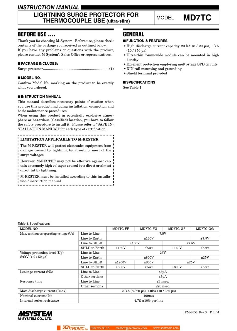
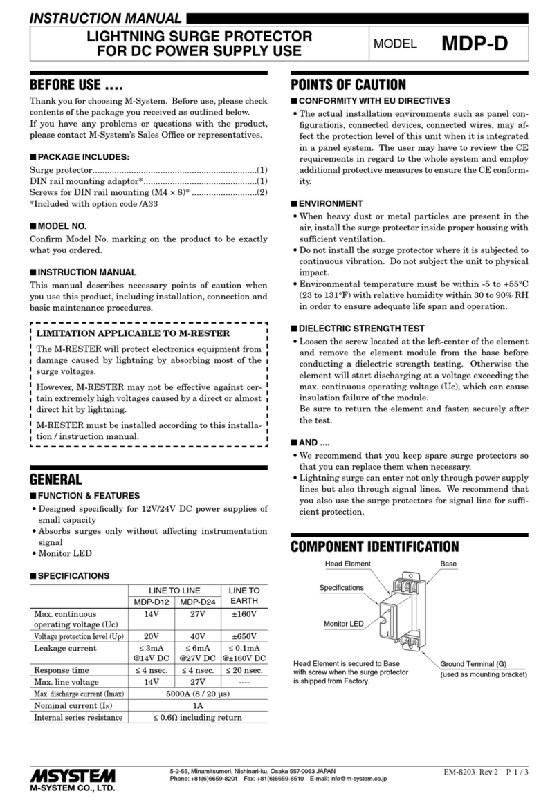
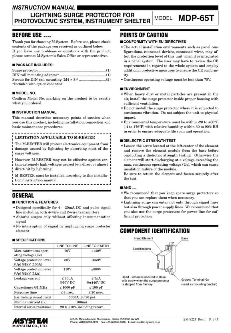
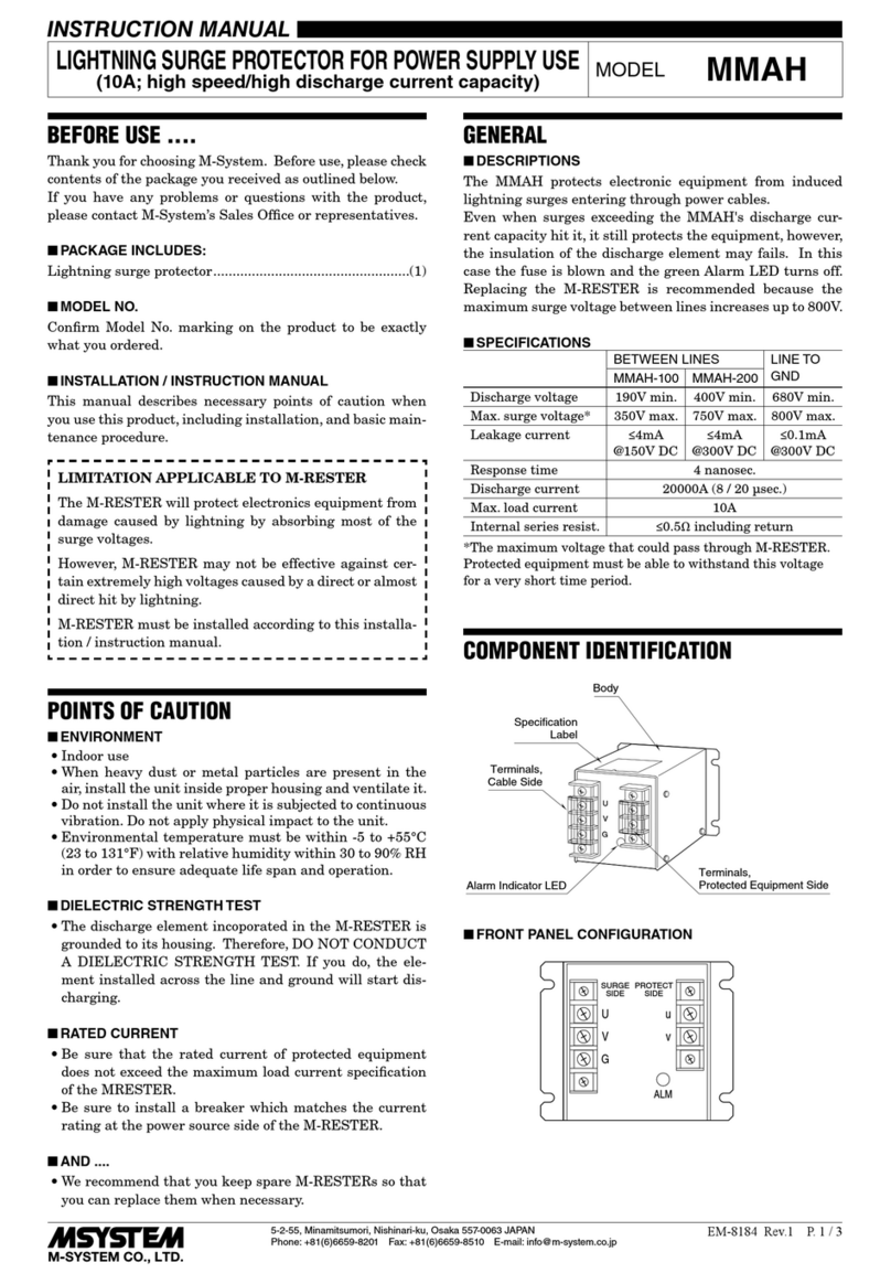
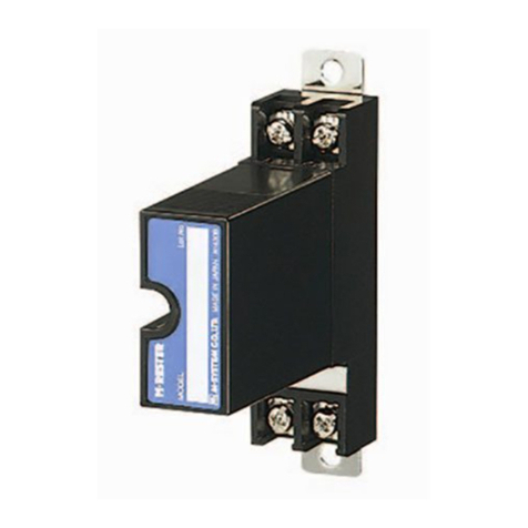
M-system MA-100 User manual

5-2-55, Minamitsumori, Nishinari-ku, Osaka 557-0063 JAPAN
Phone: +81(6)6659-8201 Fax: +81(6)6659-8510 E-mail: info@m-system.co.jp
EM-8171 Rev.8 P. 1 / 3
INSTRUCTION MANUAL
BEFORE USE ....
Thank you for choosing M-System. Before use, please check
contents of the package you received as outlined below.
If you have any problems or questions with the product,
please contact M-System’s Sales Office or representatives.
■PACKAGE INCLUDES:
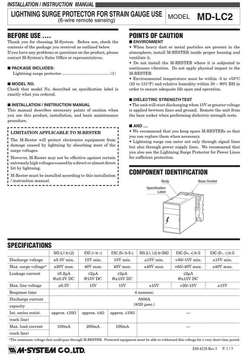
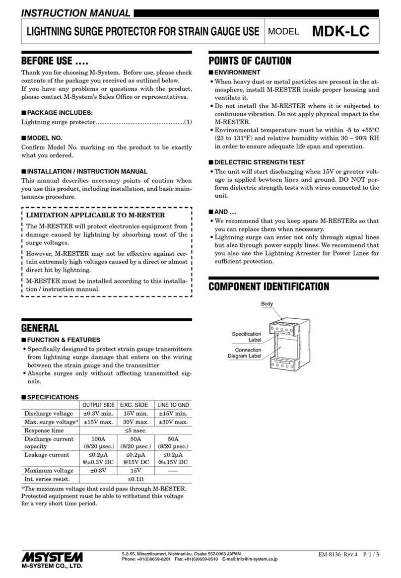
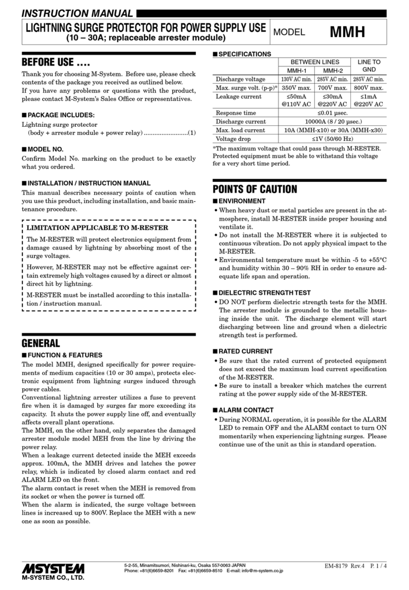
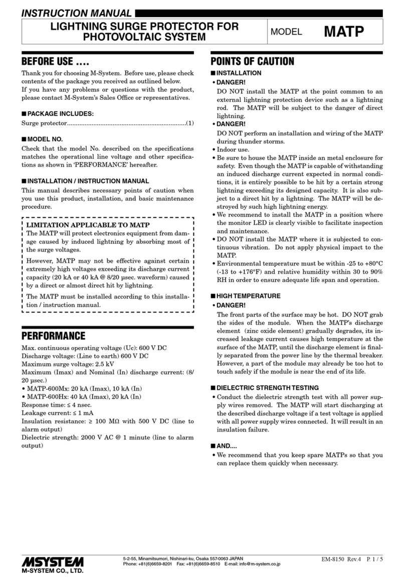
Lightning surge protector (body + base socket).................(1)
Fuse (spare parts) ...............................................................(2)
■MODEL NO.
Confirm Model No. marking on the product to be exactly
what you ordered.
■INSTRUCTION MANUAL
This manual describes necessary points of caution when
you use this product, including installation, connection and
basic maintenance procedures.
LIMITATION APPLICABLE TO M-RESTER
The M-RESTER will protect electronics equipment from
damage caused by lightning by absorbing most of the
surge voltages.
However, M-RESTER may not be effective against cer-
tain extremely high voltages caused by a direct or almost
direct hit by lightning.
M-RESTER must be installed according to this installa-
tion / instruction manual.
GENERAL
■FUNCTION & FEATURES
• Designed specifically for AC power supplies up to 2 amps
• No degradation of normal (50/60 Hz) line frequency
• Power indicator lamp provided
■SPECIFICATIONS
BETWEEN LINES LINE TO GND
MA-100 MA-200
Discharge voltage
(peak voltage)
190V min. 410V min. 410V min.
Max. surge voltage*
(peak voltage)
350V max. 700V max. 700V max.
Leakage current ≤ 1mA
@150V DC
≤ 1mA
@300V DC
≤ 1 mA
@300V DC
Rated line voltage 100V AC
110V AC
120V AC
200V AC
220V AC
240V AC
----
Response time ≤ 0.1 µsec.
Discharge current 1000A (8 / 20 µsec.)
Max. load current 2A
Voltage drop ≤ 2V (50/60 Hz)
* The maximum voltage that could pass through the surge
protector. Protected equipment must be able to withstand
this voltage for a very short time period.
POINTS OF CAUTION
■CONFORMITY WITH EU DIRECTIVES
• This equipment is suitable for use in Pollution Degree 2
and Installation Category II (transient voltage 2500V for
MA-200 and 1500V for MA-100) environments.
• Altitude up to 2000 meters.
• The equipment must be mounted inside a panel.
• The equipment must be installed such that appropriate
clearance and creepage distances are maintained to con-
form to CE requirements. Failure to observe these re-
quirements may invalidate the CE conformance.
• The actual installation environments such as panel con-
figurations, connected devices, connected wires, may af-
fect the protection level of this unit when it is integrated
in a panel system. The user may have to review the CE
requirements in regard to the whole system and employ
additional protective measures to ensure the CE conform-
ity.
■ENVIRONMENT
• Indoor use.
• When heavy dust or metal particles are present in the
air, install the surge protector inside proper housing with
sufficient ventilation.
• Do not install the surge protector where it is subjected to
continuous vibration. Do not subject the unit to physical
impact.
• Environmental temperature must be within -5 to +55°C
(23 to 131°F) with relative humidity within 30 to 90% RH
in order to ensure adequate life span and operation.
■DIELECTRIC STRENGTH TEST
• Unplug the body from the base socket before conducting a
dielectric strength test. If the test is performed with the
body, the surge protector will start discharging at the de-
scribed discharge voltage, resulting as insulation failure.
Be sure to plug the body back into the socket and secure
it with the clamps after the testing is complete.
■AND ....
• We recommend that you keep spare surge protectors so
that you can replace them when necessary.
• Lightning surge can enter not only through power supply
lines but also through signal lines. We recommend that
you also use the surge protectors for signal line for suffi-
cient protection.
LIGHTNING SURGE PROTECTOR FOR POWER SUPPLY
(2A) MODEL MA-100
MA-200
MA-100 / MA-200
5-2-55, Minamitsumori, Nishinari-ku, Osaka 557-0063 JAPAN
Phone: +81(6)6659-8201 Fax: +81(6)6659-8510 E-mail: info@m-system.co.jp
EM-8171 Rev.8 P. 2 / 3
COMPONENT IDENTIFICATION
Power Indicator LED
Body Base Socket
Specifications
Nameplate
Fuse (two)
INSTALLATION
Detach the yellow clamps located at the top and bottom of
the unit for separate the body from the base socket.
Clamp
(top & bottom)
DIN Rail
35mm wide
Spring Loaded
DIN Rail Adaptor
Shape and size of the base socket
are slightly different with various
socket types.
■DIN RAIL MOUNTING
Set the base socket so that its
DIN rail adaptor is at the bot-
tom. Position the upper hook
at the rear side of base socket
on the DIN rail and push in
the lower. When removing the
socket, push down the DIN
rail adaptor utilizing a minus
screwdriver and pull.
■WALL MOUNTING
Refer to “EXTERNAL DI-
MENSIONS.”
TERMINAL CONNECTION
Connect the unit as in the diagram below or refer to the connection diagram on the front of the unit. Be sure to cross-wire
between the Ground terminal (2, 3, 6 or 7) and the metallic housing of the protected equipment. (100 Ω max.)
■EXTERNAL DIMENSIONS unit: mm (inch)
3456
2187
50 (1.97) 95 (3.74) 20 (.79)
119.5 (4.70) [3.3 (.13)]
80 (3.15)
80 (3.15)
20
(.79)
40 (1.57)
50 (1.97)
7.8 (.31)
CLAMP
(top & bottom)
DIN RAIL
35mm wide
FUSE (two)
2–4.5 (.18) dia.
MTG HOLE
15 (.59) deep
8–M3.5
SCREW
• When mounting, no extra space is needed between units.
MONITOR
LED
■CONNECTION DIAGRAM
AC POWER
3
4
6
5
2
1
8
7
1 – 5V DC
M-RESTER
P+
G
P–
U
V
+
–
+
–
S+
S–
G
SURGE PROTECTOR
Cable
Protected
Equipment
Ground one of the terminals 2, 3, 6 and 7.
■GROUNDING
M-RESTER PROTECTED
EQUIPMENT
G
G
CROSSOVER WIRE
GROUNDING
(100 ohms or less)
A crossover wire between M-RESTER ground and the ground or
metallic housing of the equipment is required for protection.
If the protected equipment has no ground terminal, ground the
M-RESTER only.
MA-100 / MA-200
5-2-55, Minamitsumori, Nishinari-ku, Osaka 557-0063 JAPAN
Phone: +81(6)6659-8201 Fax: +81(6)6659-8510 E-mail: info@m-system.co.jp
EM-8171 Rev.8 P. 3 / 3
SURGE ABSORBER ELEMENT
When strong lightning surges exceeding the discharge cur-
rent capacity of the surge protector enter the power supply
cables, it protects the devices to some extent, but its dis-
charge element may fail. The fuse will be blown at the same
time.
Before replacing the fuse, be sure to turn off the power sup-
ply. Turn the fuse holder counterclockwise to extract the
fuse and replace it with a new one. (Refer to the figure be-
low.)
If it recovers to normal after replacing the fuse, you can
continue to use this surge protector. However, if the fuse is
blown again soon after that, it is possible that the surge pro-
tector has failed because of excessive load current. In such
a case, stop using it until a complete testing is done. Follow
the checking procedure explained in the “MAINTENANCE”
section in this manual.
SIDE VIEW
In order to remove the fuse, turn it counterclockwise
and pull it out of its holder.
Use a proper type of fuse which meets M-RESTER model
and its power supply voltage.
PARTS NO. MODEL NO. RATING
MA-100 use 200002 FGMB 125V, 2A
MA-200 use 200979 FGMB 250V, 2A
MAINTENANCE
Check surge protectors periodically. Many cases of light-
ning are ignored, and even lightning at a far distance often
causes inductive surges.
We recommend that you check your surge protector about
twice a year, before and after the rainy season. Check
whenever you experience a strong lightning occurrence.
Checking procedure is explained in the following:
■CHECKING
WIRING
1) Make sure that wiring is done as instructed in the con-
nection diagram.
2) Make sure that the Ground terminal (2, 3, 6 or 7) is con-
nected to the metallic housing of protected device.
3) Make sure that the Ground terminal (2, 3, 6 or 7) is
grounded to earth.
DISCHARGE FUNCTION
Remove all the wires connected to the surge protector and
test its discharge capability as follows:
• MA-100
1) Apply 150V DC across the terminals (1) – (8), and meas-
ure leakage current. (≤ 1mA standard)
Check also that the power indicator LED is ON.
2) Then apply 250V DC and check that the discharging oc-
curs. (≥ 2mA standard)
• MA-200
1) Apply 300V DC across the terminals (1) – (8), and meas-
ure leakage current. (≤ 1mA standard)
Check also that the power indicator LED is ON.
2) Then apply 500V DC and check that the discharging oc-
curs. (≥ 2mA standard)
• MA-100, MA-200
1) Apply 300V DC across the following terminals and meas-
ure leakage current. (≤ 1mA standard)
Terminals (1) – (2), (8) – (2)
2) Then apply 500V DC and check that the discharging oc-
curs. (≥ 2mA standard)
3) If a DC power source is not available, check resistance
across the following terminals (≥10MΩ standard).
Terminals (1) – (8), (1) – (2), (8) – (2)
4) Check that discharging occurs across the same termi-
nals with a 500V DC/1000 MΩ insulation tester. (≤ 20MΩ
standard)
If any of the above tests shows negative, replace the whole
surge protector unit.

This manual suits for next models

1

Other M-system Surge Protector manuals

M-system MDPA-24 User manual

M-system

M-system MDPA-24 User manual

M-system MD7PL User manual

M-system

M-system MD7PL User manual

M-system MD7RB-FF User manual

M-system

M-system MD7RB-FF User manual

M-system MD7G User manual

M-system

M-system MD7G User manual

M-system MD7JS User manual

M-system

M-system MD7JS User manual

M-system MDP-D Series User manual

M-system

M-system MDP-D Series User manual

M-system MD6 24 Series User manual

M-system

M-system MD6 24 Series User manual

M-system MDP-PA User manual

M-system

M-system MDP-PA User manual

M-system 6SN User manual

M-system

M-system 6SN User manual

M-system MDP-24T User manual

M-system

M-system MDP-24T User manual

M-system MDH User manual

M-system

M-system MDH User manual

M-system MH-1201 User manual

M-system

M-system MH-1201 User manual

M-system MDPA-24 User manual

M-system

M-system MDPA-24 User manual

M-system MD73W User manual

M-system

M-system MD73W User manual

M-system MDP-200T User manual

M-system

M-system MDP-200T User manual

M-system MDP-RB User manual

M-system

M-system MDP-RB User manual

M-system MATP User manual

M-system

M-system MATP User manual

M-system MDCAT 5E User manual

M-system

M-system MDCAT 5E User manual

M-system MDCAT-SPE-A User manual

M-system

M-system MDCAT-SPE-A User manual

M-system MD-LC2 Service manual

M-system

M-system MD-LC2 Service manual

M-system MDP-SP User manual

M-system

M-system MDP-SP User manual

M-system MDR2 User manual

M-system

M-system MDR2 User manual

M-system MDP-PM User manual

M-system

M-system MDP-PM User manual

M-system MDA-TL User manual

M-system

M-system MDA-TL User manual

Popular Surge Protector manuals by other brands

urmet domus 1382/21 quick start guide

urmet domus

urmet domus 1382/21 quick start guide

Asco 247120NF015ALCN0 Installation & operation manual

Asco

Asco 247120NF015ALCN0 Installation & operation manual

Radio Shack 8-Outlet Computer Network Equipment Surge... owner's manual

Radio Shack

Radio Shack 8-Outlet Computer Network Equipment Surge... owner's manual

Panamax MFP500-EX Specifications

Panamax

Panamax MFP500-EX Specifications

Shopify EVP-3PH quick guide

Shopify

Shopify EVP-3PH quick guide

Axis TU8001 installation guide

Axis

Axis TU8001 installation guide

Emerson 500 Series Installation, operation and maintenance manual

Emerson

Emerson 500 Series Installation, operation and maintenance manual

ASCO POWER TECHNOLOGIES 159 Installation & operation manual

ASCO POWER TECHNOLOGIES

ASCO POWER TECHNOLOGIES 159 Installation & operation manual

Bourns 1500 Series installation instructions

Bourns

Bourns 1500 Series installation instructions

Bits Limited SMART STRIP SCG-3MVR user guide

Bits Limited

Bits Limited SMART STRIP SCG-3MVR user guide

Austere 5S-PS6-US1 user guide

Austere

Austere 5S-PS6-US1 user guide

Total Protection Solutions ComTrack TK-CT2-190TLP4-RJ-T1/E1-C Installation, operation and maintenance manual

Total Protection Solutions

Total Protection Solutions ComTrack TK-CT2-190TLP4-RJ-T1/E1-C Installation, operation and maintenance manual

Bodet 907 052 installation manual

Bodet

Bodet 907 052 installation manual

LPS POE-8 Series installation instructions

LPS

LPS POE-8 Series installation instructions

Philips SPP7354WA/37 Specifications

Philips

Philips SPP7354WA/37 Specifications

CablesPlus GoldX PowerCore user guide

CablesPlus

CablesPlus GoldX PowerCore user guide

SECO-LARM Enforcer EVT-PB1-V1TSQ Specification sheet

SECO-LARM

SECO-LARM Enforcer EVT-PB1-V1TSQ Specification sheet

Siemens 5SD7483-5 operating instructions

Siemens

Siemens 5SD7483-5 operating instructions

manuals.online logo
manuals.online logoBrands
  • About & Mission
  • Contact us
  • Privacy Policy
  • Terms and Conditions

Copyright 2025 Manuals.Online. All Rights Reserved.