manuals.online logo
Brands
  1. Home
  2. •
  3. Brands
  4. •
  5. M-system
  6. •
  7. Surge Protector
  8. •
  9. M-system MDA-TL User manual

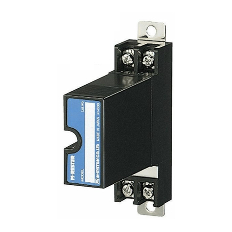
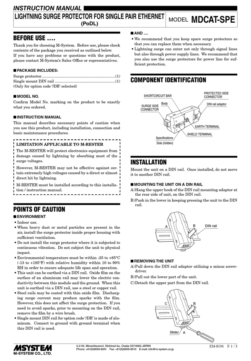
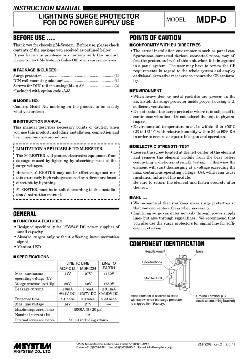
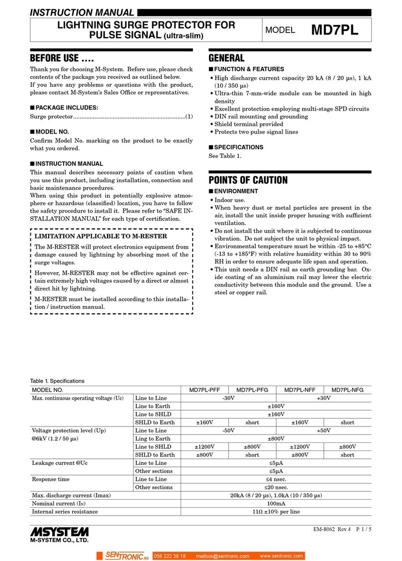
M-system MDA-TL User manual

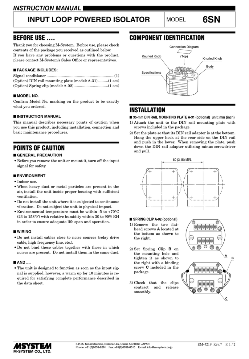
BEFORE USE ....
Thank you for choosing M-System. Before use, please check
contents of the package you received as outlined below.
If you have any problems or questions with the product,
please contact M-System’s Sales Office or representatives.
■PACKAGE INCLUDES:
Lightning surge protector (body + base socket).................(1)
■MODEL NO.
Confirm Model No. marking on the product to be exactly
what you ordered.
■INSTALLATION / INSTRUCTION MANUAL
This manual describes necessary points of caution when
you use this product, including installation, connection and
basic maintenance procedures.
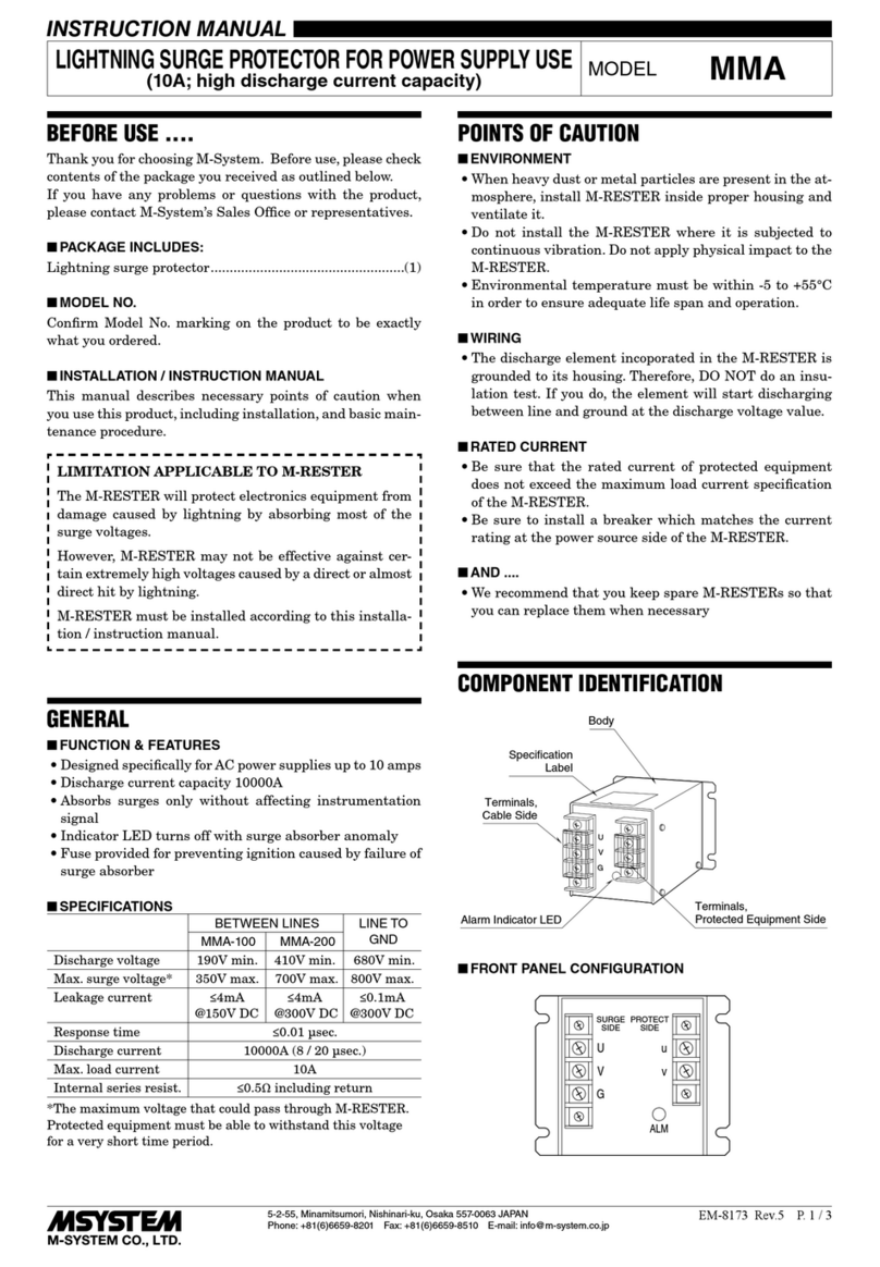
LIMITATION APPLICABLE TO M-RESTER
The M-Rester will protect electronics equipment from
damage caused by lightning by absorbing most of the
surge voltages.
However, M-Rester may not be effective against certain
extremely high voltages caused by a direct or almost di-
rect hit by lightning.
M-Rester must be installed according to this installa-
tion/ instruction manual.
GENERAL
■FUNCTION & FEATURES
• Designed specifically to protect telecommunication equip-
ment from lightning surges entering through telecommu-
nication line network
■SPECIFICATIONS
Btwn Lines Line to Gnd
Discharge voltage ±190V min. ±180V min.
Max. surge voltage* ±500V max. ±900V max.
Leakage current ≤100µA
@±160V DC
≤100µA
@±160V DC
Response time ≤0.01 µsec
Discharge current capacity
Modular jack connection
Screw terminal connection
500A (8 / 20 µsec.)
10000A (8 / 20 µsec.)
Max. load current 200mA
Internal series resistance Approx. ≤4Ω including return
Frequency band Approx. 100 kHz/-3 dB
at 600Ω terminating resistance
Max. line voltage ±160V DC
*The maximum voltage that could pass through M-RESTER.
Protected equipment must be able to withstand this voltage
for a very short time period.
POINTS OF CAUTION
■POWER INPUT RATINGS
• Power input ratings are specified by the model number
suffix code. Check the power input voltage for the unit on
the specification label.
AC power: 85 – 264V, 47 – 66 Hz, approx. 2 – 4VA
DC power: 24V ±10% or 85 – 150V, approx. 1.5W
■UNPLUGGING THE UNIT
• Before you remove the unit from its base socket or mount
it, turn off the power supply and the signal for safety.
■ENVIRONMENT
• Indoor use
• When heavy dust or metal particles are present in the
air, install the unit inside proper housing and ventilate it.
• Do not install the unit where it is subjected to continuous
vibration. Do not apply physical impact to the unit.
• Environmental temperature must be within -5 to +55°C
(23 to 131°F) with relative humidity within 30 to 90% RH
in order to ensure adequate life span and operation.
• Be sure that the ventilation slits are not covered with ca-
bles, etc.
■WIRING
• Do not install cables (power supply, input and output)
close to noise sources (relay drive cable, high frequency
line, etc.).
• Do not bind these cables together with those in which
noises are present. Do not install them in the same duct.
■AND ....
• The unit is designed to function as soon as power is sup-
plied, however, a warm up for 10 minutes is required for
satisfying complete performance described in the data
sheet.
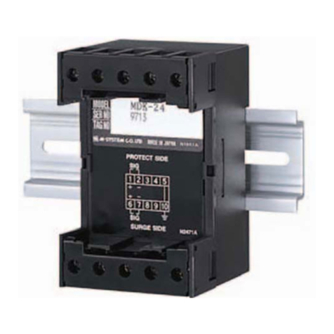
COMPONENT IDENTIFICATION
LINE
MODEM
Body
Base Socket
Specification Label
Connection Diagram
Label (side)
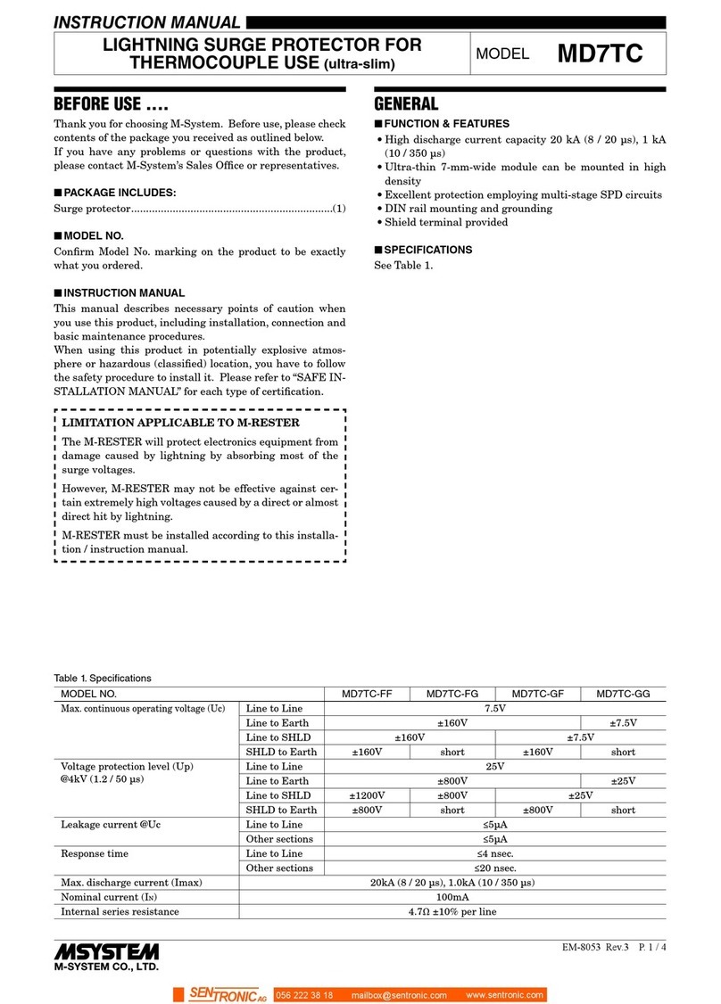
LIGHTNING SURGE PROTECTOR FOR
ANALOG TELECOM LINE USE (life monitor)
MODEL MDA-TL
5-2-55, Minamitsumori, Nishinari-ku, Osaka 557-0063 JAPAN
Phone: +81(6)6659-8201 Fax: +81(6)6659-8510 E-mail: info@m-system.co.jp
EM-8205 Rev.1 P. 1 / 3
INSTRUCTION MANUAL
■FRONT PANEL COFIGURATION
MODEM
Modular Jack
LINE
Modular Jack
MODEM
LINE
ALARM LED
PWR LED
PWR LED (green)
The green LED turns on while the power is supplied;
turns off when the power supply is removed and the
alarm output contact is also turned on.
ALM LED
The tricolor LED turns off, then on in green, amber, and
red according to the unit status.
1) Remains OFF when the power supply is first turned on.
2) Green: The unit has received one or more surges. (The
LED does not turn on when the power is not supplied.)
3) Amber: Replacement is recommended.
4) Red: The life span has ended. Replace the unit immedi-
ately. The alarm contact is turned on.
INSTALLATION
Pull out the body in pressing the clamps located at the top
and bottom of the unit for separating it from the base socket.
■DIN RAIL MOUNTING
Set the base socket so that its DIN rail adapter is at the
bottom. Hung the upper hook at the rear side of base socket
on the DIN rail and push in the lower. When removing the
socket, push down the DIN rail adapter utilizing a minus
screwdriver and pull.
DIN Rail
35mm wide
Spring Loaded
DIN Rail Adaptor
■WALL MOUNTING
Refer to the drawings in the figure below.
TERMINAL CONNECTIONS
Connect the unit as in the diagram below or refer to the connection diagram label on the side of the unit.
Be sure to make cross-wiring as shown in "GROUNDING". If the protected equipment is not provided with a G terminal,
ground only this unit's G terminal.
■EXTERNAL DIMENSIONS mm (inch)
12
34
7
6
8
5
26 (1.02)
93 (3.66)
15
(.59)
35.4 (1.39)
2–4.5 (.18)
HOLE
15 (.59) deep
DIN RAIL
35mm wide
[3.3 (.13)]
8–M3.5
SCREW
93 (3.66)
CLAMP
(top & bottom)
137 (5.39)
80 (3.15)
When mounting, no extra space is needed between units.
7.8 (.31)
26 (1.02)
107 (4.21)
MDA-TL
5-2-55, Minamitsumori, Nishinari-ku, Osaka 557-0063 JAPAN
Phone: +81(6)6659-8201 Fax: +81(6)6659-8510 E-mail: info@m-system.co.jp
EM-8205 Rev.1 P. 2 / 3
■CONNECTION DIAGRAM
1
3
4
2
5
6
L1
L2
7
8
CABLE SIDE
GROUNDING
U(+)
V(–)
ALARM OUTPUT
POWER
LINE
Modular Jack
MODEM
Modular Jack
■GROUNDING
M-RESTER PROTECTED
EQUIPMENT
G
G
CROSSOVER WIRE
GROUNDING
(100 ohms or less)
A crossover wire between M-RESTER ground and ground or metallic
housing of equipment is required for protection.
If the protected equipment has no ground terminal, ground the
M-RESTER only.
CHECKING
■WIRING
1) Make sure that wiring is done as instructed in the con-
nection diagram.
2) Power input: Check voltage across the terminal 7 – 8 with
a multimeter.
3) Make sure that Ground terminal 1 is connected to the
metallic housing of protected equipment.
4) Make sure that Ground terminal 1 is grounded to earth.
■ELEMENT MODULE
1) Shortcircuit: Check resistance across the following termi-
nals on the high-resistance range of multimeter (≥100MΩ
or infinite standard).
Terminals (L1) – (L2), (L1) – (G), (L2) – (G)
2) Discharging: Check that discharging occurs across the
same terminals with a 500V DC megger. (Indicator of the
megger must show ≤20MΩ.)
MAINTENANCE
While the ALM LED is green, regular inspections are rec-
ommended.
When it is turned to amber, replacement of the unit is rec-
ommended.
When it is turned to and remain red, replace the unit im-
mediately.
CAUTION
Before replacing the unit, be sure to turn off the power sup-
ply for safety. Other factors such like an alarm system con-
nected
to the line should also be considered.
The life monitoring circuit remain alive due to the inter-
nal backup power even when the external power supply is
removed. The LED is turned off in that case. The backup
power is normally effective for approximately one week de-
pending upon environmental conditions.
MDA-TL
5-2-55, Minamitsumori, Nishinari-ku, Osaka 557-0063 JAPAN
Phone: +81(6)6659-8201 Fax: +81(6)6659-8510 E-mail: info@m-system.co.jp
EM-8205 Rev.1 P. 3 / 3

Other M-system Surge Protector manuals

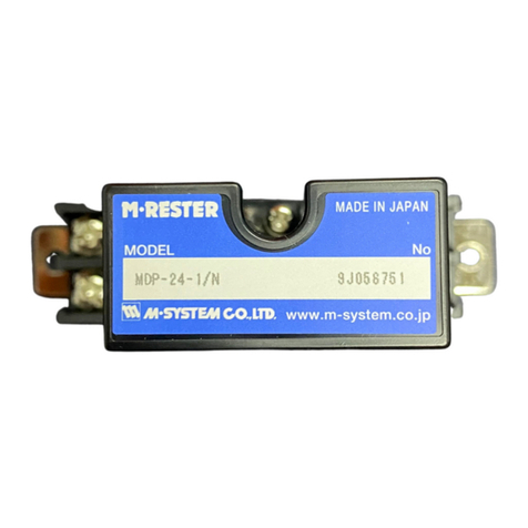
M-system MDP-24-1 User manual

M-system

M-system MDP-24-1 User manual

M-system MGD-24 User manual

M-system

M-system MGD-24 User manual

M-system MAT2 Series User manual

M-system

M-system MAT2 Series User manual

M-system MAKN User manual

M-system

M-system MAKN User manual

M-system MDR2 User manual

M-system

M-system MDR2 User manual

M-system MD6x-24 User manual

M-system

M-system MD6x-24 User manual

M-system MDCAT 5E User manual

M-system

M-system MDCAT 5E User manual

M-system MDP-LWA User manual

M-system

M-system MDP-LWA User manual

M-system MD7LWA User manual

M-system

M-system MD7LWA User manual

M-system MDP-PA User manual

M-system

M-system MDP-PA User manual

M-system MMA User manual

M-system

M-system MMA User manual

M-system MDP-TL User manual

M-system

M-system MDP-TL User manual

M-system MD7JS User manual

M-system

M-system MD7JS User manual

M-system MDP-4R User manual

M-system

M-system MDP-4R User manual

M-system MDP-24T User manual

M-system

M-system MDP-24T User manual

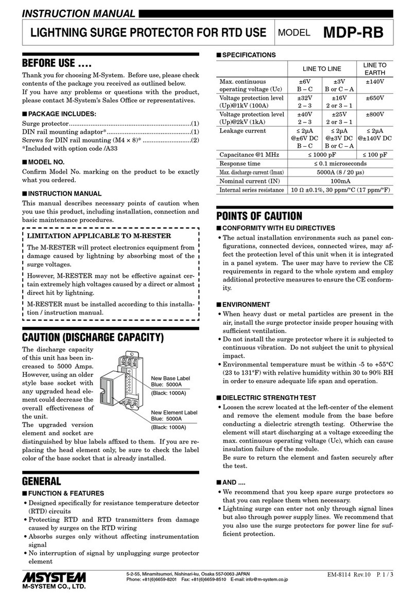
M-system MDP-RB User manual

M-system

M-system MDP-RB User manual

M-system MMAJ User manual

M-system

M-system MMAJ User manual

M-system MDP-200T User manual

M-system

M-system MDP-200T User manual

M-system MD73W User manual

M-system

M-system MD73W User manual

M-system MDCAT-SPE-A User manual

M-system

M-system MDCAT-SPE-A User manual

M-system MDP-LWA User manual

M-system

M-system MDP-LWA User manual

M-system MDPA-24 User manual

M-system

M-system MDPA-24 User manual

M-system MD7PM User manual

M-system

M-system MD7PM User manual

M-system MD74R User manual

M-system

M-system MD74R User manual

Popular Surge Protector manuals by other brands

CPT PSM3-30/750 TNC Series installation instructions

CPT

CPT PSM3-30/750 TNC Series installation instructions

CPT PSM4 Series installation instructions

CPT

CPT PSM4 Series installation instructions

Philips SPP3211WB Specifications

Philips

Philips SPP3211WB Specifications

Wiremold legrand SENTREX installation instructions

Wiremold

Wiremold legrand SENTREX installation instructions

CPT PSC3 Series quick start guide

CPT

CPT PSC3 Series quick start guide

PSP Hurricane 2000 Series installation instructions

PSP

PSP Hurricane 2000 Series installation instructions

QVS PP136M Specification sheet

QVS

QVS PP136M Specification sheet

Ultra Products ULT33063 user manual

Ultra Products

Ultra Products ULT33063 user manual

Nexxt Solutions NHP-T720 user guide

Nexxt Solutions

Nexxt Solutions NHP-T720 user guide

Rocket Fish RF-HTS210 Guide d'installation rapide

Rocket Fish

Rocket Fish RF-HTS210 Guide d'installation rapide

Tripp Lite HT706TV owner's manual

Tripp Lite

Tripp Lite HT706TV owner's manual

Rocket Fish RF-HTS205 Limited warranty

Rocket Fish

Rocket Fish RF-HTS205 Limited warranty

Tripp Lite B110-SP-CAT quick start guide

Tripp Lite

Tripp Lite B110-SP-CAT quick start guide

Rocket Fish RF-HTS110 Guide d'installation rapide

Rocket Fish

Rocket Fish RF-HTS110 Guide d'installation rapide

Tripp Lite LC 1200 owner's manual

Tripp Lite

Tripp Lite LC 1200 owner's manual

Rocket Fish RF-HTS205 Limited warranty

Rocket Fish

Rocket Fish RF-HTS205 Limited warranty

WorkPro ESD 10K user manual

WorkPro

WorkPro ESD 10K user manual

Tripp Lite ISOBAR6 Specification sheet

Tripp Lite

Tripp Lite ISOBAR6 Specification sheet

manuals.online logo
manuals.online logoBrands
  • About & Mission
  • Contact us
  • Privacy Policy
  • Terms and Conditions

Copyright 2025 Manuals.Online. All Rights Reserved.