manuals.online logo
Brands
  1. Home
  2. •
  3. Brands
  4. •
  5. M-system
  6. •
  7. Surge Protector
  8. •
  9. M-system MDP-DM3 User manual

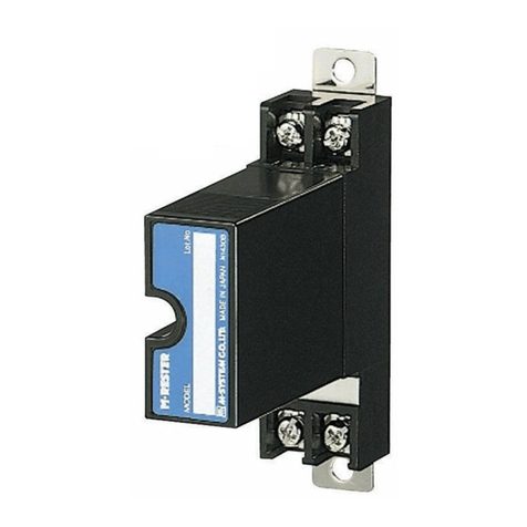
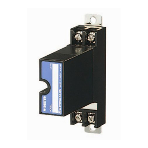
M-system MDP-DM3 User manual

5-2-55, Minamitsumori, Nishinari-ku, Osaka 557-0063 JAPAN
Phone: +81(6)6659-8201 Fax: +81(6)6659-8510 E-mail: info@m-system.co.jp
EM-8110 Rev.9 P. 1 / 3
INSTRUCTION MANUAL
LIGHTNING SURGE PROTECTOR FOR MsysNet USE
MODEL MDP-DM3
BEFORE USE ....
Thank you for choosing M-System. Before use, please check
contents of the package you received as outlined below.
If you have any problems or questions with the product,
please contact M-System’s Sales Office or representatives.
■PACKAGE INCLUDES:
Surge protector....................................................................(1)
DIN rail mounting adaptor*...............................................(1)
Screws for DIN rail mounting (M4 × 8)* ...........................(2)
*Included with option code /A33
■MODEL NO.
Confirm Model No. marking on the product to be exactly
what you ordered.
■INSTRUCTION MANUAL
This manual describes necessary points of caution when
you use this product, including installation, connection and
basic maintenance procedures.
LIMITATION APPLICABLE TO M-RESTER
The M-RESTER will protect electronics equipment from
damage caused by lightning by absorbing most of the
surge voltages.
However, M-RESTER may not be effective against cer-
tain extremely high voltages caused by a direct or almost
direct hit by lightning.
M-RESTER must be installed according to this installa-
tion / instruction manual.
GENERAL
■FUNCTION & FEATURES
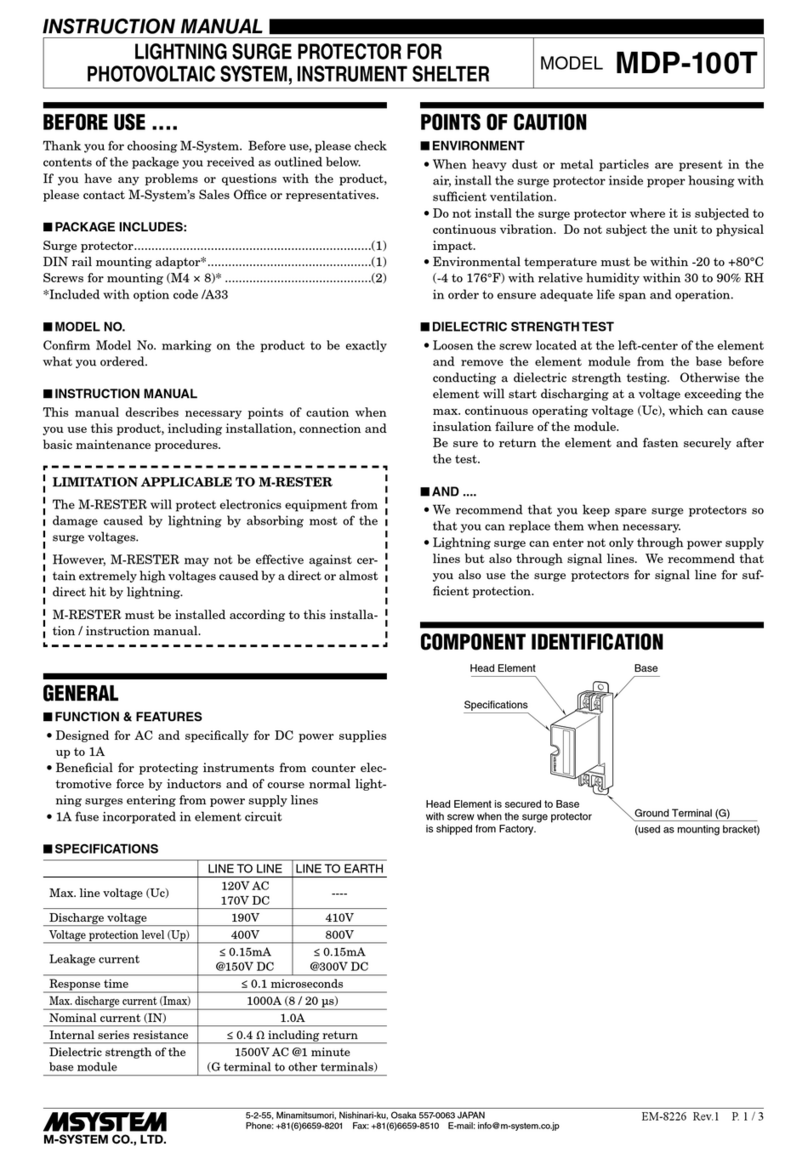
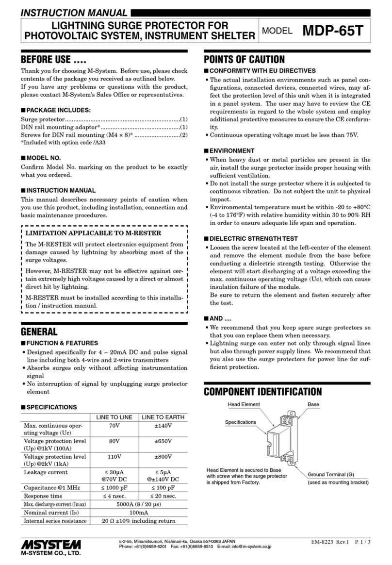
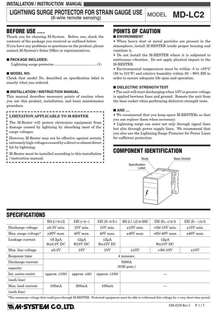
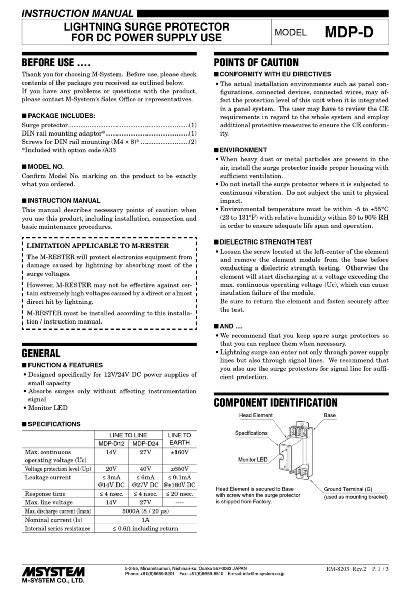
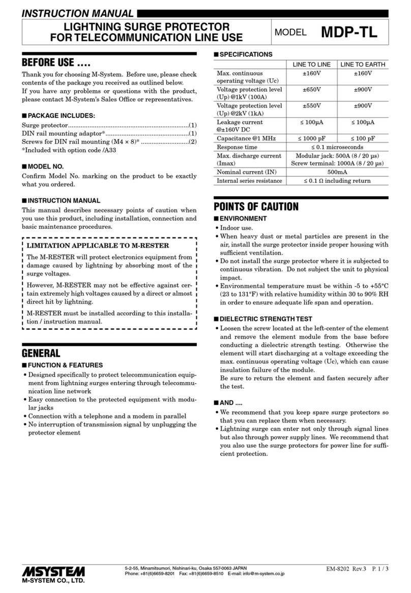
• Designed specifically for the network
• No interruption of transmission signal by unplugging the
head element module
■SPECIFICATIONS
LINE TO LINE LINE TO
EARTH
Max. continuous
operating voltage (Uc)
±5V
B – C
5V
B or C – A
±140V
Voltage protection level
(Up) @1kV (100A)
±10V
2 – 3
10V
2 or 3 – 1
±650V
Voltage protection level
(Up) @2kV (1kA)
±20V
2 – 3
20V
2 or 3 – 1
±800V
Leakage current ≤ 0.2mA
@±5V
B – C
≤ 0.2mA
@5V
B or C – A
≤ 10µA
@±140V
Capacitance @1 MHz ≤ 20 nF ≤ 50 pF
Response time ≤ 0.1 microseconds
Max. discharge current(Imax)
5000A (8 / 20 µs)
Nominal current (IN) 100mA
Internal series resistance
4 Ω ±10% including return
Input attenuation
-0.5 dB or less @DC...100 kHz, Z0 = 110 Ω
POINTS OF CAUTION
■ENVIRONMENT
• When heavy dust or metal particles are present in the
air, install the surge protector inside proper housing with
sufficient ventilation.
• Do not install the surge protector where it is subjected to
continuous vibration. Do not subject the unit to physical
impact.
• Environmental temperature must be within -5 to +55°C
(23 to 131°F) with relative humidity within 30 to 90% RH
in order to ensure adequate life span and operation.
■DIELECTRIC STRENGTH TEST
• Loosen the screw located at the left-center of the element
and remove the element module from the base before
conducting a dielectric strength testing. Otherwise the
element will start discharging at a voltage exceeding the
max. continuous operating voltage (Uc), which can cause
insulation failure of the module.
Be sure to return the element and fasten securely after
the test.
■AND ....
• We recommend that you keep spare surge protectors so
that you can replace them when necessary.
• Lightning surge can enter not only through signal lines
but also through power supply lines. We recommend that
you also use the surge protectors for power line for suffi-
cient protection.
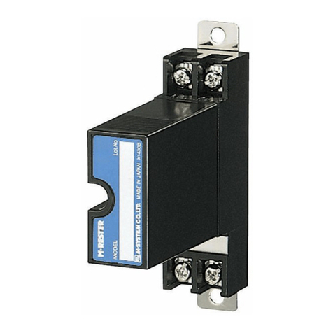
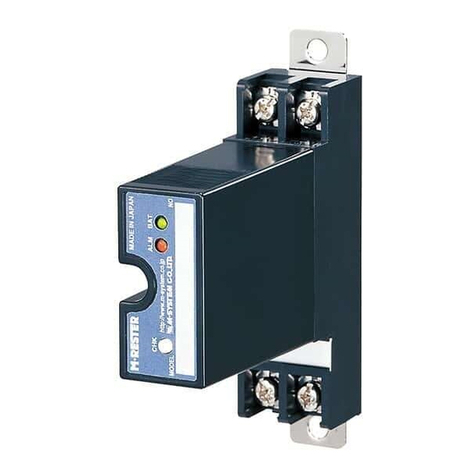
COMPONENT IDENTIFICATION
Ground Terminal (G)
(used as mounting bracket)
Base
Element is secured to Base
with screw when M-RESTER is
shipped from Factory.
M•RESTER
MADE IN JAPAN N1430B
Lot.NO
MODEL
Head Element
Specifications
MDP-DM3
5-2-55, Minamitsumori, Nishinari-ku, Osaka 557-0063 JAPAN
Phone: +81(6)6659-8201 Fax: +81(6)6659-8510 E-mail: info@m-system.co.jp
EM-8110 Rev.9 P. 2 / 3
INSTALLATION
In order to separate the head element from the base, loosen the screw located at the left-center of the element.
■WALL MOUNTING
Refer to the drawings below.
• EXTERNAL DIMENSIONS unit: mm (inch)
B
C
23
A
1
31.5 (1.24)
2–5 (.20) dia.
MTG HOLE
6–M4 SCREW
GROUND TERMINAL (G)
(used as mounting bracket)
27 (1.06)53 (2.08)
80 (3.15)
45 (1.77)
HEAD ELEMENT
BASE
80 (3.15)
90 (3.54)
100 (3.94)
33 (1.30) min. 2–M4 SCREW
90 (3.54)
• MOUNTING REQUIREMENTS
unit: mm (inch)
■DIN RAIL MOUNTING (Only for /A33)
1. MOUNTING ONTO THE ADAPTOR
Before DIN rail mounting, secure the mounting bracket of
MDP to the mounting adaptor with a screw provided with
this product. In this step, secure at one point.
M•RESTER
2. DIN RAIL MOUNTING
Set the base socket so that its mounting slider is at the bot-
tom. Position the upper hook at the rear side of base socket
on the DIN rail and push in the lower. When removing the
socket, push down the mounting slider utilizing a minus
screwdriver and pull.
DIN Rail Mounting Slider
35 mm wide
DIN Rail
3. GROUNDING
Secure the mounting bracket at the other point with the
other screw. In this step, secure the grounding wire togeth-
er with the screw.
M•RESTER
Solderless Terminal
• MOUNTING REQUIREMENTS unit: mm (inch)
8.5
(.33)
[3.3 (.13)]
DIN RAIL
35mm wide
80 (3.15)
45 (1.77)
4
(.18)
2–M4 MOUNTING SCREW
(used as ground terminal (G))
MDP-DM3
5-2-55, Minamitsumori, Nishinari-ku, Osaka 557-0063 JAPAN
Phone: +81(6)6659-8201 Fax: +81(6)6659-8510 E-mail: info@m-system.co.jp
EM-8110 Rev.9 P. 3 / 3
TERMINAL CONNECTION
Connect the unit as in the diagram below.
Be sure to cross-wire between the Ground terminal (G) and that of the protected equipment. When the surge protector is con-
nected with a device which has no ground terminal such like M-System’s (See figure below), ground the M-RESTER Ground
terminal (G) only.
(Protected Device)(Protected Device)
C
B
3
2
MDP-DM3
G
A
1
3
2
MDP-DM3
Shielded Twisted-pair Cable
RS-422/485
Communication Line
G
C
B
A1
FG
+
–
SHLD
FG
+
–
SHLD
Grounding
≤100Ω
Grounding
≤100Ω
*1*1
*2*2
*3*3
*4*4
*1. Applicable devices: M-System’s MsysNet or SIN-NET devices which employ RS-422/485 communication standards.
*2. Recommended cable length between the surge protector and the protected device: 1 meter at the maximum
*3. No connection is required if the protected device has no shield terminal.
*4. Cross wire between the protected device’s FG terminal and the surge protector’s G terminal, and ground to the earth
at the surge protector side.
Ground only the surge protector if the protected device has no FG terminal.
■GROUNDING
M-RESTER PROTECTED
EQUIPMENT
G
G
CROSSOVER WIRE
GROUNDING
(100 ohms or less)
A crossover wire between M-RESTER ground and the ground or
metallic housing of the equipment is required for protection.
If the protected equipment has no ground terminal, ground the
M-RESTER only.
When the M-RESTER is mounted with DIN Rail Mounting Adapter,
connect the grounding wire to the mounting screw of the M-RESTER.
WIRING INSTRUCTIONS
■SCREW TERMINAL
Torque: 0.8 N·m
MAINTENANCE
Check surge protectors periodically. Many cases of light-
ning are ignored, and even lightning at a far distance often
causes inductive surges.
We recommend that you check your surge protector about
twice a year, before and after the rainy season. Check
whenever you experience a strong lightning occurrence.
Checking procedure is explained in the following:
■CHECKING
WIRING
1) Make sure that wiring is done as instructed in the con-
nection diagram.
2) Make sure that the Ground terminal (G) is connected to
the metallic housing of protected equipment.
3) Make sure that the Ground terminal (G) is grounded to
earth.
DISCHARGE FUNCTION
The M-RESTER Tester is available for a preliminary check-
ing of the surge protector’s head element. For detailed
checking, send the surge protector back to M-System.
It is not applicable to the products manufactured earlier
than Year 2004 (identified by 8-digit serial No. starting with
H through M, or 4-digit serial No.).
Approximate testing procedure without using the Tester is
explained as below.
1) Remove all wiring connected to the surge protector when
you test the element module.
2) Check resistance across the following terminals on the
high resistance range of multimeter (measuring current
≤ 0.25µA) and confirm no conduction. The meter shows ≥
10MΩ at (A) – (G), ≥1MΩ at other terminals. When meas-
uring across (A) – (B) and (A) – (C), connect the probes so
that positive voltage is applied to (B) and (C) respectively.
Terminals (A) – (B), (A) – (C), (B) – (C)
(A) – (G), (B) – (G), (C) – (G)
3) Confirm conduction across the same terminals with a
500V DC 1000MΩ insulation tester (The tester shows ≤
20MΩ).
If any of the above tests shows negative, please contact
M-System’s Sales Office or representatives.

Other M-system Surge Protector manuals

M-system MD7FB User manual

M-system

M-system MD7FB User manual

M-system MDP-65T User manual

M-system

M-system MDP-65T User manual

M-system MDP-RB User manual

M-system

M-system MDP-RB User manual

M-system MDP-24-1 User manual

M-system

M-system MDP-24-1 User manual

M-system MAKN User manual

M-system

M-system MAKN User manual

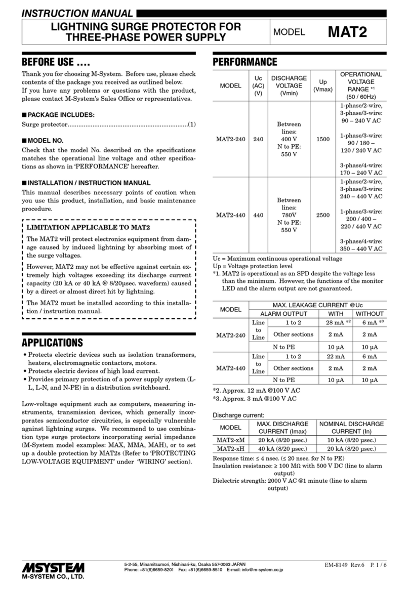
M-system MAT2 Series User manual

M-system

M-system MAT2 Series User manual

M-system MDPA-24 User manual

M-system

M-system MDPA-24 User manual

M-system MD6 24 Series User manual

M-system

M-system MD6 24 Series User manual

M-system MDA-TL User manual

M-system

M-system MDA-TL User manual

M-system MD6x-24 User manual

M-system

M-system MD6x-24 User manual

M-system MDH User manual

M-system

M-system MDH User manual

M-system MATP User manual

M-system

M-system MATP User manual

M-system MD7PM User manual

M-system

M-system MD7PM User manual

M-system MD73W User manual

M-system

M-system MD73W User manual

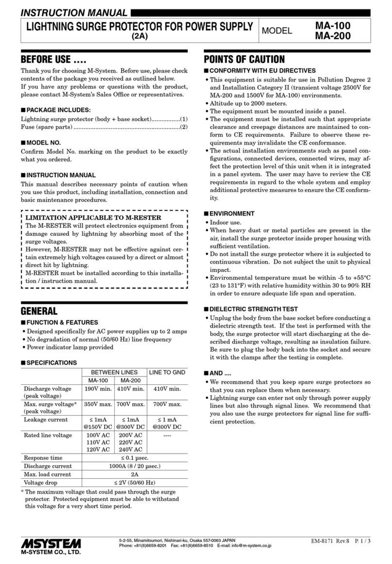
M-system MDP-100 User manual

M-system

M-system MDP-100 User manual

M-system MD7LC User manual

M-system

M-system MD7LC User manual

M-system MDK-24 User manual

M-system

M-system MDK-24 User manual

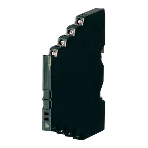
M-system MD7G User manual

M-system

M-system MD7G User manual

M-system MDP-LWA User manual

M-system

M-system MDP-LWA User manual

M-system MD7PL User manual

M-system

M-system MD7PL User manual

M-system MDP-TL User manual

M-system

M-system MDP-TL User manual

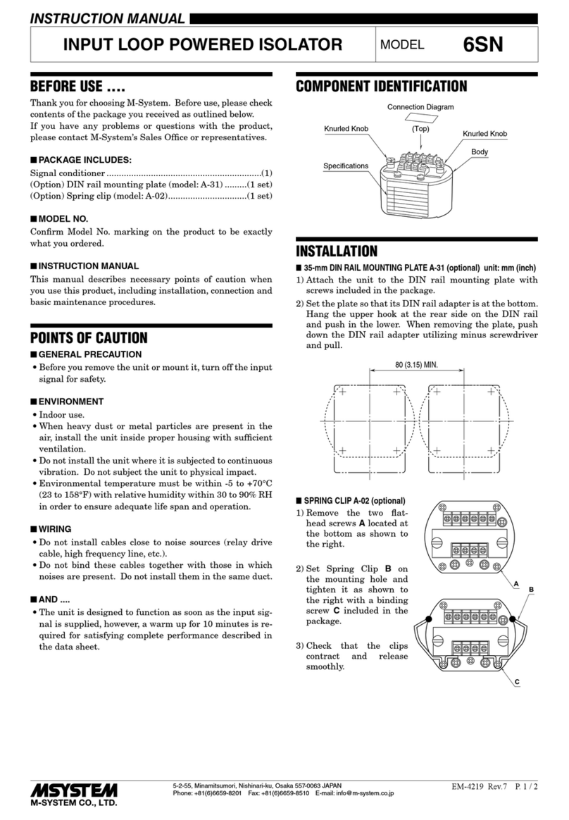
M-system 6SN User manual

M-system

M-system 6SN User manual

M-system MDCAT-SPE User manual

M-system

M-system MDCAT-SPE User manual

M-system MDP-4R User manual

M-system

M-system MDP-4R User manual

Popular Surge Protector manuals by other brands

THOR DRM1050 installation guide

THOR

THOR DRM1050 installation guide

Schaudt OVP 01 A Operating and installation instructions

Schaudt

Schaudt OVP 01 A Operating and installation instructions

Mobotix MX-OVERVOLTAGE-PROTECTION-BOX Quick install

Mobotix

Mobotix MX-OVERVOLTAGE-PROTECTION-BOX Quick install

Belkin Conserve Smart AV user guide

Belkin

Belkin Conserve Smart AV user guide

Panamax M8-HT instructions

Panamax

Panamax M8-HT instructions

Radio Shack 61-2404 owner's manual

Radio Shack

Radio Shack 61-2404 owner's manual

Manitowoc Q-DUAL SERIES 4004489 installation instructions

Manitowoc

Manitowoc Q-DUAL SERIES 4004489 installation instructions

SurgeX Defender Series user manual

SurgeX

SurgeX Defender Series user manual

Belkin F7C01008 user guide

Belkin

Belkin F7C01008 user guide

Axis T8061 installation guide

Axis

Axis T8061 installation guide

LEGRAND 0 505 10 quick guide

LEGRAND

LEGRAND 0 505 10 quick guide

Crestron PC-100 Do guide

Crestron

Crestron PC-100 Do guide

Sven SF-08-16 user manual

Sven

Sven SF-08-16 user manual

Leviton 51005-WM installation guide

Leviton

Leviton 51005-WM installation guide

Patton electronics 540 user manual

Patton electronics

Patton electronics 540 user manual

Total Protection Solutions ComTrack TK-CT2-DB9 Installation, operation and maintenance manual

Total Protection Solutions

Total Protection Solutions ComTrack TK-CT2-DB9 Installation, operation and maintenance manual

Radio Shack 61-2423 owner's manual

Radio Shack

Radio Shack 61-2423 owner's manual

Bauhn AP5ODM-0224-W user guide

Bauhn

Bauhn AP5ODM-0224-W user guide

manuals.online logo
manuals.online logoBrands
  • About & Mission
  • Contact us
  • Privacy Policy
  • Terms and Conditions

Copyright 2025 Manuals.Online. All Rights Reserved.