manuals.online logo
Brands
  1. Home
  2. •
  3. Brands
  4. •
  5. M-system
  6. •
  7. Surge Protector
  8. •
  9. M-system MDP-100 User manual

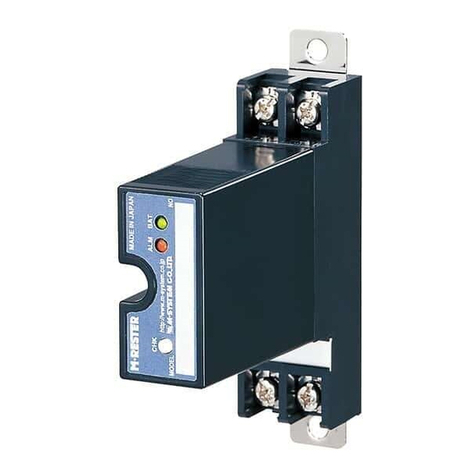
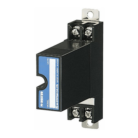
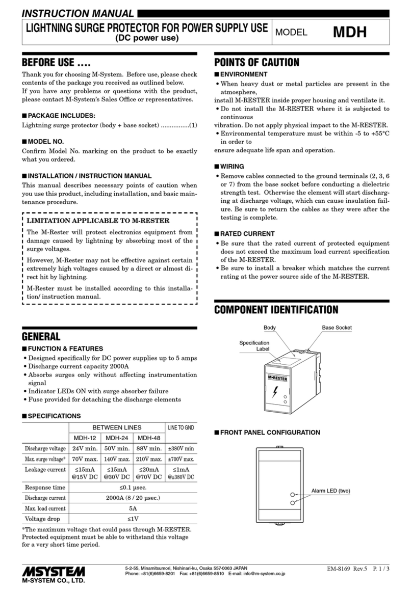
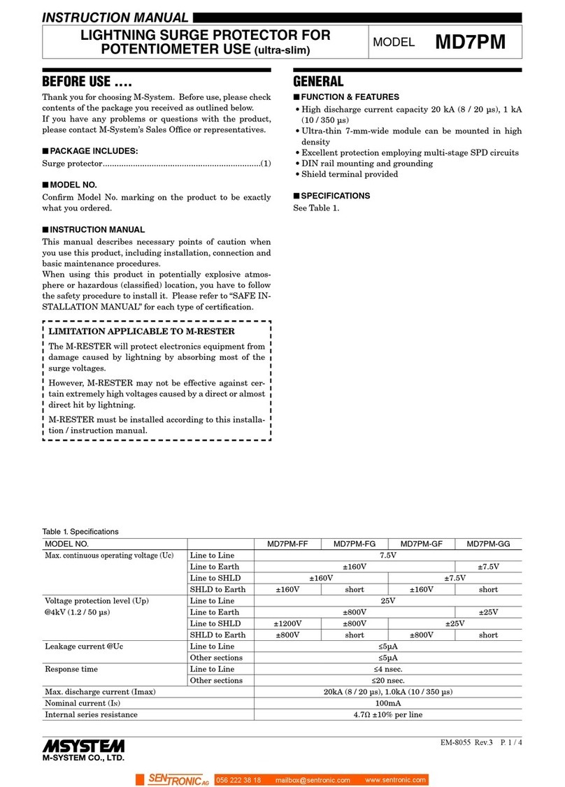
M-system MDP-100 User manual

5-2-55, Minamitsumori, Nishinari-ku, Osaka 557-0063 JAPAN
Phone: +81(6)6659-8201 Fax: +81(6)6659-8510 E-mail: info@m-system.co.jp
EM-8121 Rev.9 P. 1 / 3
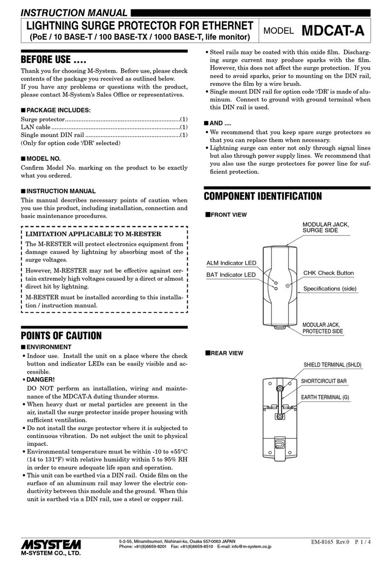
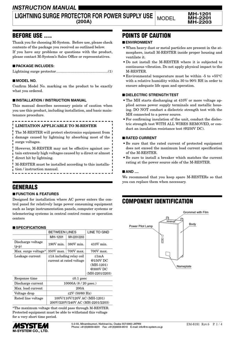
INSTRUCTION MANUAL
LIGHTNING SURGE PROTECTOR FOR
AC/DC POWER SUPPLY USE (1A) MODEL
MDP-100
MDP-200
BEFORE USE ....
Thank you for choosing M-System. Before use, please check
contents of the package you received as outlined below.
If you have any problems or questions with the product,
please contact M-System’s Sales Office or representatives.
■PACKAGE INCLUDES:
Surge protector....................................................................(1)
DIN rail mounting adaptor*...............................................(1)
Screws for DIN rail mounting (M4 × 8)* ...........................(2)
*Included with option code /A33
■MODEL NO.
Confirm Model No. marking on the product to be exactly
what you ordered.
■INSTRUCTION MANUAL
This manual describes necessary points of caution when
you use this product, including installation, connection and
basic maintenance procedures.
LIMITATION APPLICABLE TO M-RESTER
The M-RESTER will protect electronics equipment from
damage caused by lightning by absorbing most of the
surge voltages.
However, M-RESTER may not be effective against cer-
tain extremely high voltages caused by a direct or almost
direct hit by lightning.
M-RESTER must be installed according to this installa-
tion / instruction manual.
GENERAL
■FUNCTION & FEATURES
• Designed for AC and specifically for DC power supplies
up to 1A
• Beneficial for protecting instruments from counter elec-
tromotive force by inductors and of course normal light-
ning surges entering from power supply lines
• 1A fuse incorporated in element circuit
■SPECIFICATIONS
LINE TO LINE LINE TO
EARTH
MDP-100 MDP-200
Max. line voltage (Uc) 120V AC
170V DC
250V AC
355V DC ----
Discharge voltage 190V 410V 410V
Voltage protection level (Up)
400V 800V 800V
Leakage current ≤ 0.1mA
@150V DC
≤ 0.1mA
@300V DC
≤ 0.1mA
@300V DC
Response time ≤ 0.1 microsecond.
Max. discharge current (Imax)
1000A (8 / 20 µs)
Nominal current (IN) 1.0A
Internal series resistance ≤ 0.4 Ω including return
Dielectric strength of the
base module
1500V AC @1 minute
(G terminal to other terminals)
POINTS OF CAUTION
■ENVIRONMENT
• When heavy dust or metal particles are present in the
air, install the surge protector inside proper housing with
sufficient ventilation.
• Do not install the surge protector where it is subjected to
continuous vibration. Do not subject the unit to physical
impact.
• Environmental temperature must be within -5 to +60°C
(23 to 140°F) with relative humidity within 30 to 90% RH
in order to ensure adequate life span and operation.
■DIELECTRIC STRENGTH TEST
• Loosen the screw located at the left-center of the element
and remove the element module from the base before
conducting a dielectric strength testing. Otherwise the
element will start discharging at a voltage exceeding the
max. continuous operating voltage (Uc), which can cause
insulation failure of the module.
Be sure to return the element and fasten securely after
the test.
■AND ....
• We recommend that you keep spare surge protectors so
that you can replace them when necessary.
• Lightning surge can enter not only through power supply
lines but also through signal lines. We recommend that
you also use the surge protectors for signal line for suffi-
cient protection.
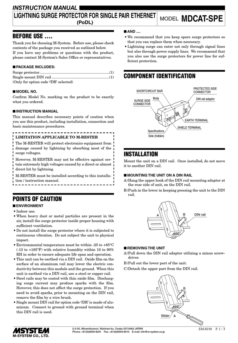
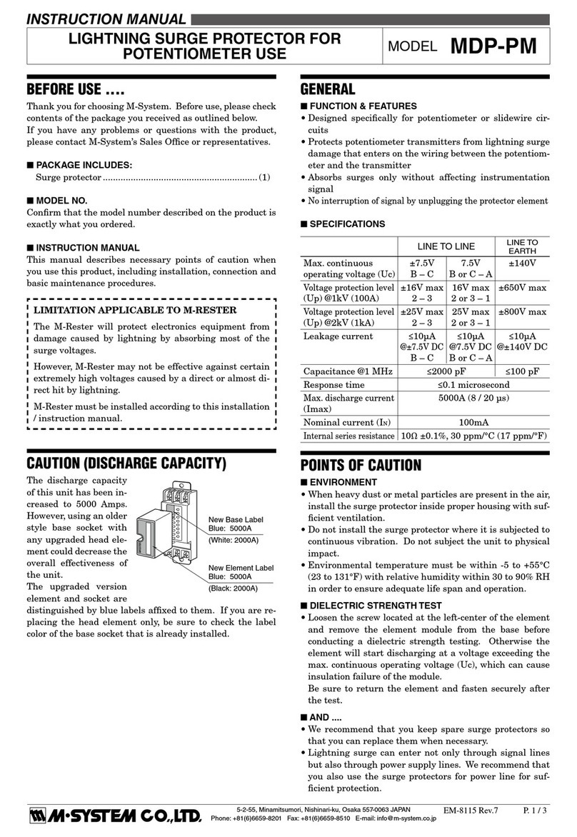
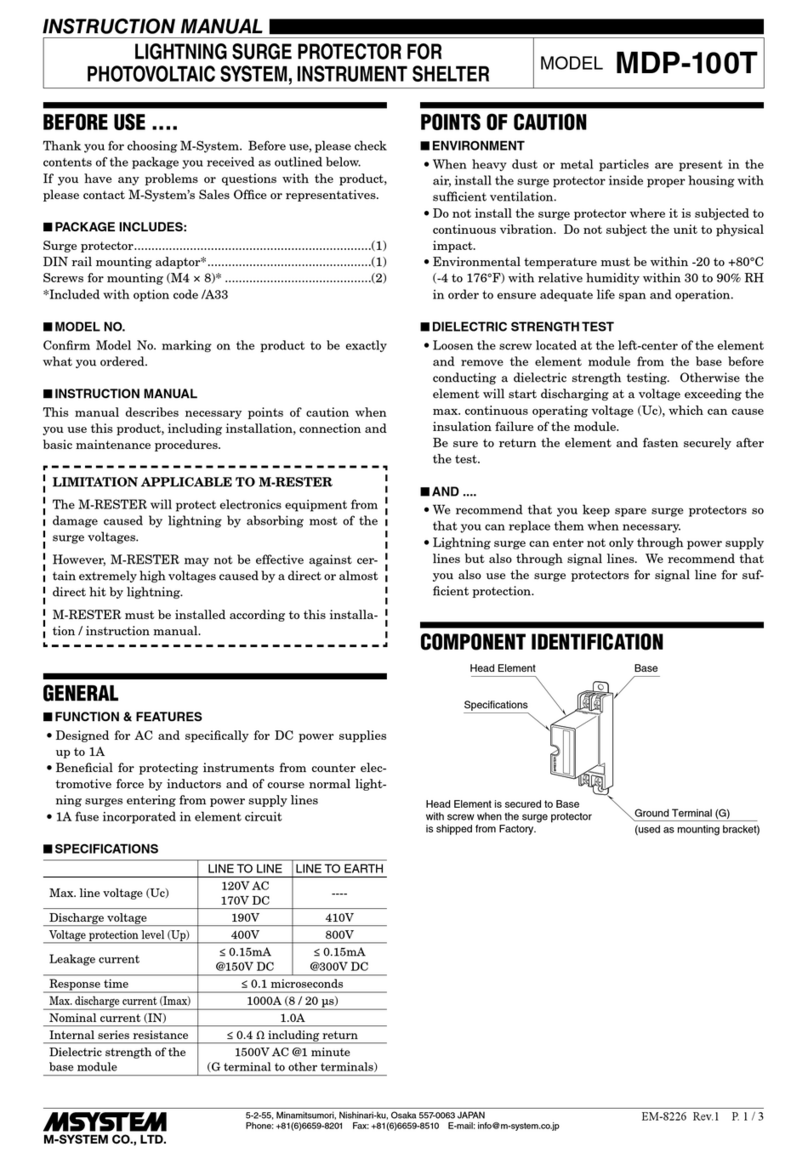
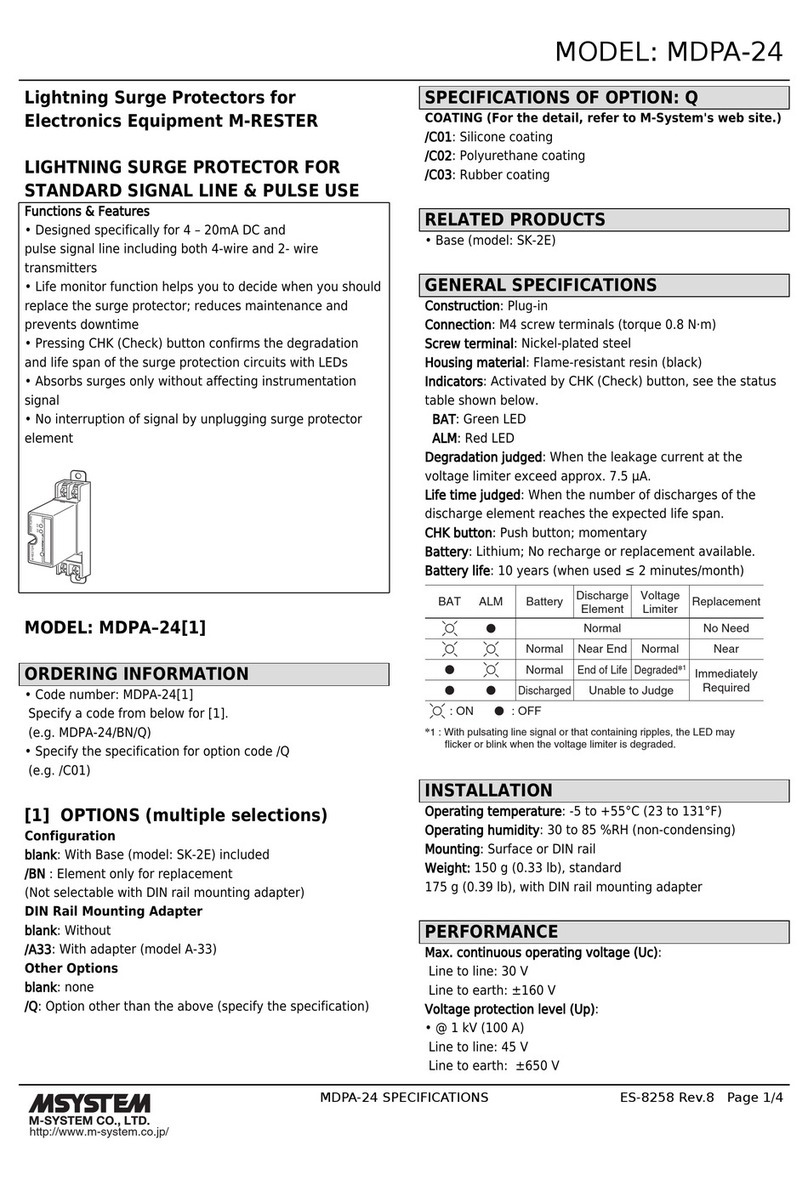
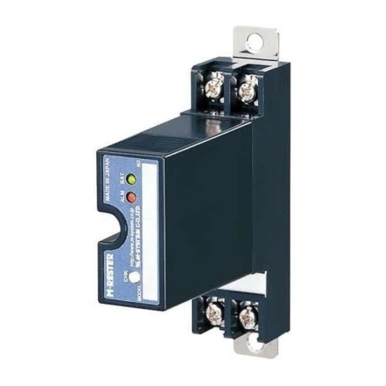
COMPONENT IDENTIFICATION
M•RESTER
Ground Terminal (G)
(used as mounting bracket)
Head Element Base
Specifications
Head Element is secured to Base
with screw when the surge protector
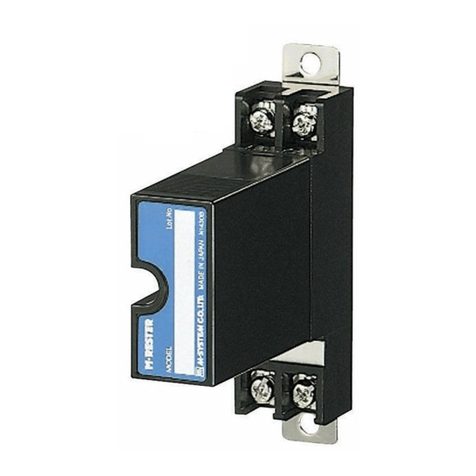
is shipped from Factory.
MDP-100 / MDP-200
5-2-55, Minamitsumori, Nishinari-ku, Osaka 557-0063 JAPAN
Phone: +81(6)6659-8201 Fax: +81(6)6659-8510 E-mail: info@m-system.co.jp
EM-8121 Rev.9 P. 2 / 3
INSTALLATION
In order to separate the head element from the base, loosen the screw located at the left-center of the element.
■WALL MOUNTING
Refer to the drawings below.
• EXTERNAL DIMENSIONS unit: mm (inch)
25 (.97) min. 2–M4 SCREW
90 (3.54)
P2P1
S2S1
23.5 (.93)
80 (3.15)
2–5 (.20) dia.
MTG HOLE
90 (3.54)
100 (3.94)
4–M4 TERMINAL SCREW
GROUND TERMINAL (G)
(used as mounting bracket)
27 (1.06)53 (2.09)
80 (3.15)
45 (1.77)
HEAD ELEMENT
BASE
• MOUNTING REQUIREMENTS
unit: mm (inch)
■DIN RAIL MOUNTING (Only for /A33)
1. MOUNTING ONTO THE ADAPTOR
Before DIN rail mounting, secure the mounting bracket of
MDP to the mounting adaptor with a screw provided with
this product. In this step, secure at one point.
DIN Rail Mounting Adaptor
M•RESTER
2. DIN RAIL MOUNTING
Set the base socket so that its mounting slider is at the bot-
tom. Position the upper hook at the rear side of base socket
on the DIN rail and push in the lower. When removing the
socket, push down the mounting slider utilizing a minus
screwdriver and pull.
DIN Rail Mounting Slider
35 mm wide
DIN Rail
3. GROUNDING
Secure the mounting bracket at the other point with the
other screw. In this step, secure the grounding wire togeth-
er with the screw.
M•RESTER
Solderless Te r
minal
• MOUNTING REQUIREMENTS unit: mm (inch)
8.5
(.33)
[3.3 (.13)]
DIN RAIL
35mm wide
80 (3.15)
45 (1.77)
4
(.18)
2–M4 MOUNTING SCREW
(used as ground terminal (G))
MDP-100 / MDP-200
5-2-55, Minamitsumori, Nishinari-ku, Osaka 557-0063 JAPAN
Phone: +81(6)6659-8201 Fax: +81(6)6659-8510 E-mail: info@m-system.co.jp
EM-8121 Rev.9 P. 3 / 3
TERMINAL CONNECTION
Connect the unit as in the diagram below.
Be sure to cross-wire between the Ground terminal (G) and that of the protected equipment.
P1
P2
S1
S2
M-RESTER
Relay,
Coil, etc.
G
Discharge
Element
P1
P2
M-RESTER
G
Discharge
Element
1A R
CONTROL ROOM
FIELD
The M-RESTER must be connected with its terminals S1 and S2 faced on power source side
in order that the fuses would be blown in case of shortcircuit of the discharge element.
1A
1A
1A
S1
S2
■GROUNDING
M-RESTER PROTECTED
EQUIPMENT
G
G
CROSSOVER WIRE
GROUNDING
(100 ohms or less)
A crossover wire between M-RESTER ground and the ground or
metallic housing of the equipment is required for protection.
If the protected equipment has no ground terminal, ground the
M-RESTER only.
When the M-RESTER is mounted with DIN Rail Mounting Adapter,
connect the grounding wire to the mounting screw of the M-RESTER.
WIRING INSTRUCTIONS
■SCREW TERMINAL
Torque: 0.8 N·m
MAINTENANCE
Check surge protectors periodically. Many cases of light-
ning are ignored, and even lightning at a far distance often
causes inductive surges.
We recommend that you check your surge protector about
twice a year, before and after the rainy season. Check
whenever you experience a strong lightning occurrence.
Checking procedure is explained in the following:
■CHECKING
WIRING
1) Make sure that wiring is done as instructed in the con-
nection diagram.
2) Make sure that the Ground terminal (G) is connected to
the metallic housing of protected equipment.
3) Make sure that the Ground terminal (G) is grounded to
earth.
DISCHARGE FUNCTION
The M-RESTER Tester is available for checking the ele-
ment module of this surge protector.
If you do not have one, approximate checking can be con-
ducted as following.
1) Remove all wiring connected to the surge protector when
you test the element module.
2) Check resistance across the following terminals on the
high resistance range of multimeter and confirm no con-
duction. The meter shows the same value as it will show
when these terminals are open.
Terminals (S1) – (S2), (P1) – (P2)
3) Check that discharging occurs across the following ter-
minals with a 500V DC 1000 MΩ insulation tester (The
tester shows ≤ 20MΩ).
Terminals (S1) – (S2), (S1) – (G), (S2) – (G)
If any of the above tests shows negative, replace the pro-
tector.

This manual suits for next models

1

Other M-system Surge Protector manuals
M-system MD7G User manual

M-system

M-system MD7G User manual

M-system MDK-24 User manual

M-system

M-system MDK-24 User manual

M-system MDR2 User manual

M-system

M-system MDR2 User manual

M-system MDH User manual

M-system

M-system MDH User manual

M-system MD73W User manual

M-system

M-system MD73W User manual

M-system MD7JS User manual

M-system

M-system MD7JS User manual

M-system MAKN User manual

M-system

M-system MAKN User manual

M-system MD7TC User manual

M-system

M-system MD7TC User manual

M-system MDP-DM3 User manual

M-system

M-system MDP-DM3 User manual

M-system MDP-200T User manual

M-system

M-system MDP-200T User manual

M-system MDA-TL User manual

M-system

M-system MDA-TL User manual

M-system MDP-D Series User manual

M-system

M-system MDP-D Series User manual

M-system MAL-230x User manual

M-system

M-system MAL-230x User manual

M-system MD6x-24 User manual

M-system

M-system MD6x-24 User manual

M-system MDPA-24 User manual

M-system

M-system MDPA-24 User manual

M-system MDP-RB User manual

M-system

M-system MDP-RB User manual

M-system MDP-SP User manual

M-system

M-system MDP-SP User manual

M-system MDCAT-A Series User manual

M-system

M-system MDCAT-A Series User manual

M-system MDCAT 5E User manual

M-system

M-system MDCAT 5E User manual

M-system MDP-24-1 User manual

M-system

M-system MDP-24-1 User manual

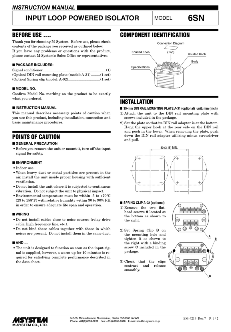
M-system 6SN User manual

M-system

M-system 6SN User manual

M-system MDCAT-SPE-A User manual

M-system

M-system MDCAT-SPE-A User manual

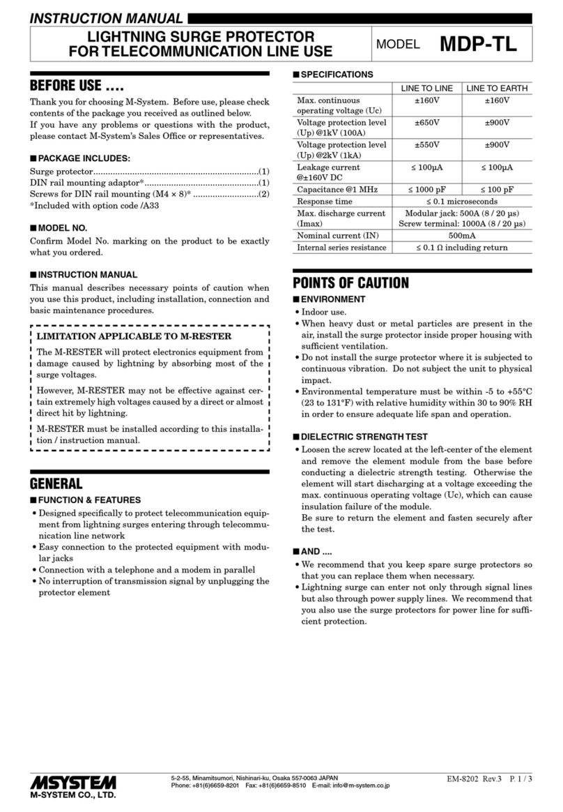
M-system MDP-TL User manual

M-system

M-system MDP-TL User manual

M-system MGA-100 User manual

M-system

M-system MGA-100 User manual

Popular Surge Protector manuals by other brands
Infinite Transtector ALPU PTP INJ installation instructions

Infinite

Infinite Transtector ALPU PTP INJ installation instructions

Asco Series 300 Installation & operation manual

Asco

Asco Series 300 Installation & operation manual

Ilsco SSI SpecPRO CSM 16 Series manual

Ilsco

Ilsco SSI SpecPRO CSM 16 Series manual

ASCO POWER TECHNOLOGIES 277 Installation & operation manual

ASCO POWER TECHNOLOGIES

ASCO POWER TECHNOLOGIES 277 Installation & operation manual

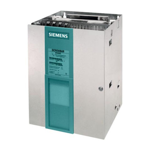
Siemens 3TX7402-3A operating instructions

Siemens

Siemens 3TX7402-3A operating instructions

Philips SPP7354WA/37 Specifications

Philips

Philips SPP7354WA/37 Specifications

Eaton Crouse-hinds series instruction sheet

Eaton

Eaton Crouse-hinds series instruction sheet

UTEPO USP201V user manual

UTEPO

UTEPO USP201V user manual

Black & Decker BDXPA0052 instruction manual

Black & Decker

Black & Decker BDXPA0052 instruction manual

INVISIBLE FENCE Indoor Micro Shields manual

INVISIBLE FENCE

INVISIBLE FENCE Indoor Micro Shields manual

Moxa Technologies ISD-1100 Series Hardware installation guide

Moxa Technologies

Moxa Technologies ISD-1100 Series Hardware installation guide

Patton electronics 574 user manual

Patton electronics

Patton electronics 574 user manual

Infinite TRANSTECTOR ALPU-TSU installation instructions

Infinite

Infinite TRANSTECTOR ALPU-TSU installation instructions

Adcom ACE-615 owner's manual

Adcom

Adcom ACE-615 owner's manual

Southwire Surge Guard 34850 troubleshooting guide

Southwire

Southwire Surge Guard 34850 troubleshooting guide

OBO Bettermann CombiController V50-280 Series installation instructions

OBO Bettermann

OBO Bettermann CombiController V50-280 Series installation instructions

INFOSEC UPS SYSTEM S8 LAN TV user guide

INFOSEC UPS SYSTEM

INFOSEC UPS SYSTEM S8 LAN TV user guide

Transtector CB Series installation instructions

Transtector

Transtector CB Series installation instructions

manuals.online logo
manuals.online logoBrands
  • About & Mission
  • Contact us
  • Privacy Policy
  • Terms and Conditions

Copyright 2025 Manuals.Online. All Rights Reserved.