M-system MEX-D User manual
MEX-D
P. 1 / 3 EM-4616 Rev.7
BEFORE USE ....
Thank you for choosing M-System. Before use, check the
contents of the package you received as outlined below.
If you have any problems or questions with the product,
please contact M-System’s Sales Office or representatives.
■ PACKAGE INCLUDES:
Signal conditioner (body + base socket) ..................... (1)
■ MODEL NO.
Check that model No. described on specification label is
exactly what you ordered.
■ INSTRUCTION MANUAL
This manual describes necessary points of caution when you
use this product, including installation, connection and basic
maintenance procedures.
POINTS OF CAUTION
■ POWER INPUT RATING & OPERATIONAL RANGE
• Check the power rating for the unit on the specification label.
Rating ±10%, 50/60 ±2 Hz, approx. 3VA
■ UNPLUGGING THE UNIT
• Before you remove the unit from its base socket or mount it,
turn off the power supply and input signal for safety.
■ ENVIRONMENT
• Indoor use
• When heavy dust or metal particles are present in the air,
install the unit inside proper housing with sufficient ventila-
tion.
• Do not install the unit where it is subjected to continuous
vibration. Do not subject the unit to physical impact.
• Environmental temperature must be within -5 to +60°C (23
to140°F)withrelativehumiditywithin 30 to 90% RHin order
to ensure adequate life span and operation.
■ WIRING
• Do not install cables (power supply, input and output) close
to noise sources (relay drive cable, high frequency line, etc.).
• Do not bind these cables together with those in which noises
are present. Do not install them in the same duct.
■ MOTOR
• The internal SSR is not designed to direct-reverse driving
for a 200V AC motor.
■ AND ....
• The unit is designed to function as soon as power is
supplied, however, a warm up for 10 minutes is required for
satisfying complete performance described in the data sheet.
INSTRUCTION MANUAL
MODEL MEX-D
VALVE POSITIONER
(current feedback; built-in SSR)
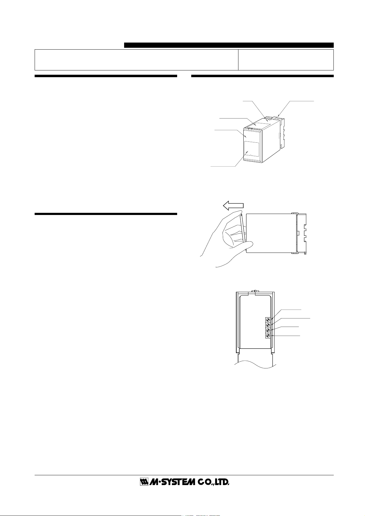
COMPONENT IDENTIFICATION
■ HOW TO OPEN THE FRONT COVER:
Position your finger on the hook at the top of front cover and
pull.
■FRONT PANEL CONFIGURATIONS
The shape of base socket may be different
for some models.
Body Base Socket
Connection
Diagram Label
Front Cover
Specification
Label
Span Adj.
Zero Adj.
Deadband Adj.
Timer Adj.

MEX-D
P. 2 / 3 EM-4616 Rev.7
INSTALLATION
Detach the yellow clamps located at the top and bottom of the
unit for separating the body from the base socket.
■ DIN RAIL MOUNTING
Set the base socket so that its
DIN rail adaptor is at the bot-
tom. Position the upper hook
at the rear side of base socket
on the DIN rail and push in the
lower. When removing the
socket, push down the DIN rail
adaptor utilizing a minus
screwdriver and pull.
■ WALL MOUNTING
Refer to the drawings below.
■ DIMENSIONS mm (inch)
■ CONNECTION DIAGRAM
Clamp
(top & bottom)
DIN Rail
35mm wide
Spring Loaded
DIN Rail Adaptor
Shape and size of the base socket
are slightly different with various
socket types.
TERMINAL CONNECTIONS
Connect the unit as in the diagram below or refer to the connection diagram label on top of the unit.
5678
21
1110
80 (3.15)
50 (1.97) 107 (4.21)
136 (5.35) [3.3 (.13)]
80 (3.15)
20
(.79)
35.4 (1.39)
40 (1.57)
50 (1.97)
7.8 (.31)
CLAMP
(top & bottom)
DIN RAIL
35mm wide
2–4.5 (.18) dia.
MTG HOLE
25 (.98) deep
11–M3.5
SCREW
•When mounting, no extra space is needed between units.
39
4
5
6
4
2
7
8
U
V
3
AC MOTOR
POWER
1
10
11
min.
max.
M
FEEDBACK
+
–
+
–
+
A
SETPOINT
RE-TRANSMITTED OUTPUT

MEX-D
P. 3 / 3 EM-4616 Rev.7
CHECKING
1) Terminal wiring: Check that all cables are correctly
connected according to the connection diagram.
2) Power input voltage: Check voltage across the terminal 7
–␣ 8 with a multimeter.
3) Input: Check voltage across the terminals 5 (+) – 6 (–) to
show within 0.4 to 2V.
4) Feedback signal: Check voltage across the terminals 10 –
11 to show within 80 to 400mV.
5) Output: Check voltage across the output terminals.
Output Operation
ON: ≤2V AC across the output terminals
OFF: 60 – 280V AC across the output terminals
When deviation between the setpoint and the position is
narrower than deadband, the output terminals show the
status equal to ‘SET = POS.’
ADJUSTMENTS
■ CONNECTING TO THE MOTOR
The motor must be connected carefully considering the rela-
tion between the motor’s rotating direction and the feedback
signal. If the connection is inappropriate, the MEX, upon
startup, drives the motor until it hits either end of span with
no control capability in midspan.
■ DEADBAND
The deadband is factory set to the maximum value (20%).
Turn the adjustment counterclockwise until hunting stops.
Adjustable within 2 to 20%.
■ MOTOR POSITIONING
0% Position
Apply 0% setpoint signal and adjust the 0% output position
with Zero Adjustment. Adjustable within 0 to 25%.
100% Position
Apply 100% setpoint signal and adjust the 100% output
position with Span Adjustment. Adjustable within 75 to
100%.
POWER ON OFF
OUT. TERM.
SET < POS SET = POS SET > POS –
1 – 3 OFF OFF ON OFF
2 – 3 ON OFF OFF OFF
■ TIMER
Set minimum interval for open/close operation, used for
protecting control motor from too frequent open/close opera-
tion. Adjustable to 1 – 30 seconds.
Deadband adjustment can realize similar effects. Combine
these two functions according to the control loop characteris-
tics to minimize the motor’s operation and prevent it from
overheating and wearing unnecessarily.
MAINTENANCE
Regular calibration procedure is explained below:
■ CALIBRATION
Confirm the motor position at 0%, 50% and 100% input
signals.
LIGHTNING SURGE PROTECTION
In order to product the unit from lightning surges entering
through power supply cables, use of appropriate Lightning
Surge Protectors are recommended. Please contact M-Sys-
tem.
M-SYSTEM WARRANTY
M-System warrants such new M-System product which it manufactures to be free from defects in materials and workmanship during the 36-month period following the date that such
productwasoriginallypurchasedifsuchproducthasbeenusedundernormaloperatingconditionsandproperlymaintained,M-System'ssoleliability,andpurchaser'sexclusiveremedies,
under this warranty are, at M-System's option, the repair, replacement or refund of the purchase price of any M-System product which is defective under the terms of this warranty. To
submit a claim under this warranty, the purchaser must return, at its expense, the defective M-System product to the below address together with a copy of its original sales invoice.
THIS IS THE ONLY WARRANTY APPLICABLE TO M-SYSTEM PRODUCT AND IS IN LIEU OF ALL OTHER WARRANTIES, EXPRESS OR IMPLIED, INCLUDING ANY IMPLIED
WARRANTIES OF MERCHANTABILITY OR FITNESS FOR A PARTICULAR PURPOSE. M-SYSTEM SHALL HAVE NO LIABILITY FOR CONSEQUENTIAL, INCIDENTAL OR
SPECIAL DAMAGES OF ANY KIND WHATSOEVER.
M-System Co., Ltd., 5-2-55, Minamitsumori, Nishinari-ku, Osaka 557-0063 JAPAN, Phone: (06) 6659-8201, Fax: (06) 6659-8510, E-mail: [email protected]
Other M-system Valve Positioner manuals

Popular Valve Positioner manuals by other brands


Parker
Parker MX80L series product manual

Westlock
Westlock Quantum 2800 Installation & operating instructions

Samson
Samson 3730-0 Mounting and operating instructions

Samson
Samson TROVIS 3730-3 Mounting and operating instructions

ESCO Technologies
ESCO Technologies ETS LINDGREN 2302-001 user manual

SMC Networks
SMC Networks IP8000 manual

Samson
Samson FOUNDATION 3730-5 Mounting and operating instructions

Samson
Samson TROVIS SAFE 3731-3 Mounting and operating instructions

Flowserve
Flowserve Logix 3400MD User instructions

halstrup-walcher
halstrup-walcher HIPERDRIVE instruction manual

ABB
ABB TZIDC Commissioning instructions

Samson
Samson FOUNDATION 3730-5 Mounting and operating instructions