Mabit SmartControl User manual

- 1 -
MAB 2010280101 EN V2.2
www.mabit.pl info@mabit.pl
SmartControl – Instruction Manual
MAB 2010280101 EN V2.
2

- 2 -
MAB 2010280101 EN V2.2
www.mabit.pl info@mabit.pl
1. Safety information...................................................................................................................- 4 -
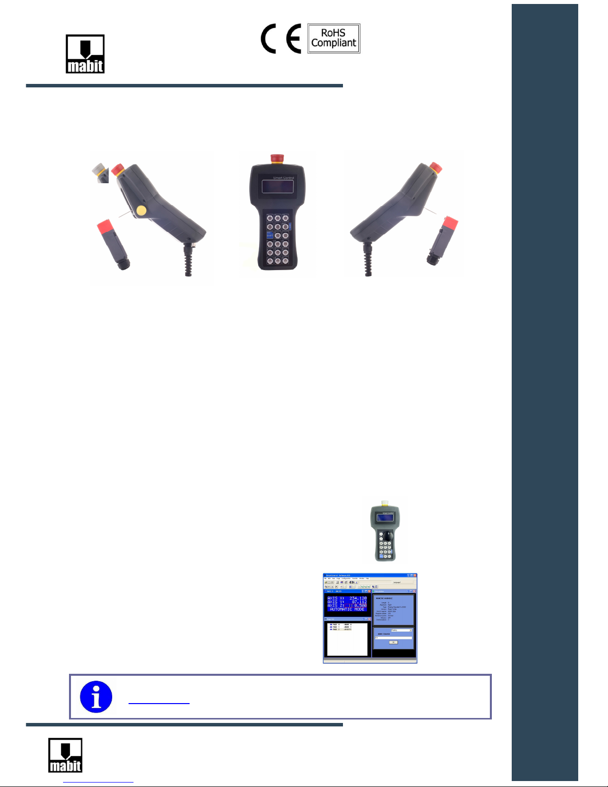
2. Introduction.............................................................................................................................- 5 -
2.1. Main features ...................................................................................................................- 5 -
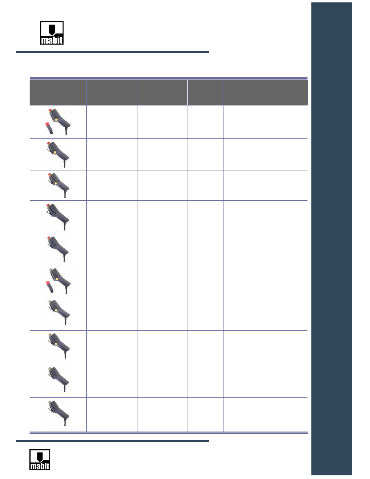
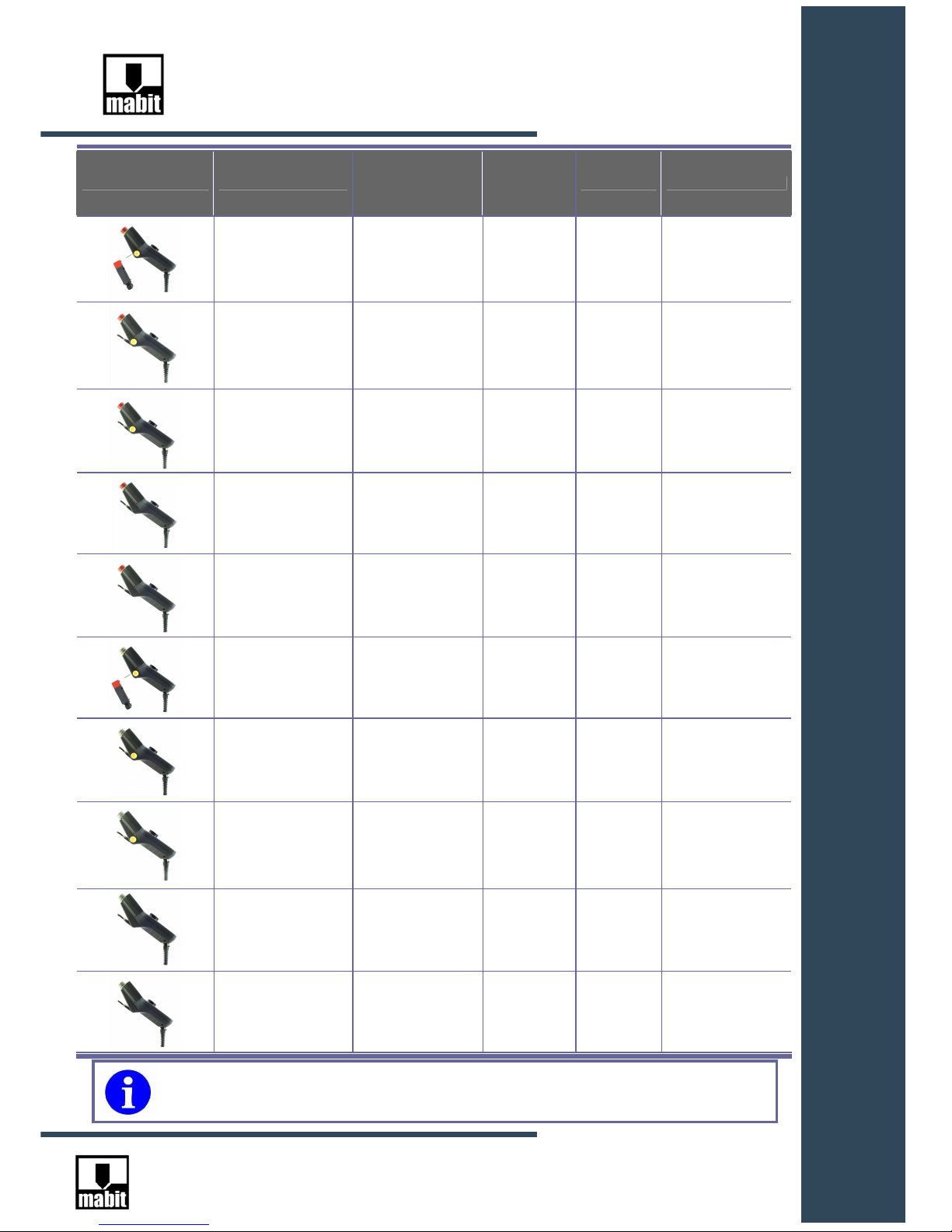
2.2. Ordering...........................................................................................................................- 6 -
2.3. Nameplate........................................................................................................................- 9 -
3. Technical data ......................................................................................................................- 10 -
3.1. Technical data of SmartControl......................................................................................- 10 -
3.2. Technical data of Hand wheel........................................................................................- 11 -
3.3. Technical data of butli-in emergency off switch/stop (IDEC)..........................................- 12 -
3.4. Technical data of butli-in enabling switch (IDEC)...........................................................- 13 -
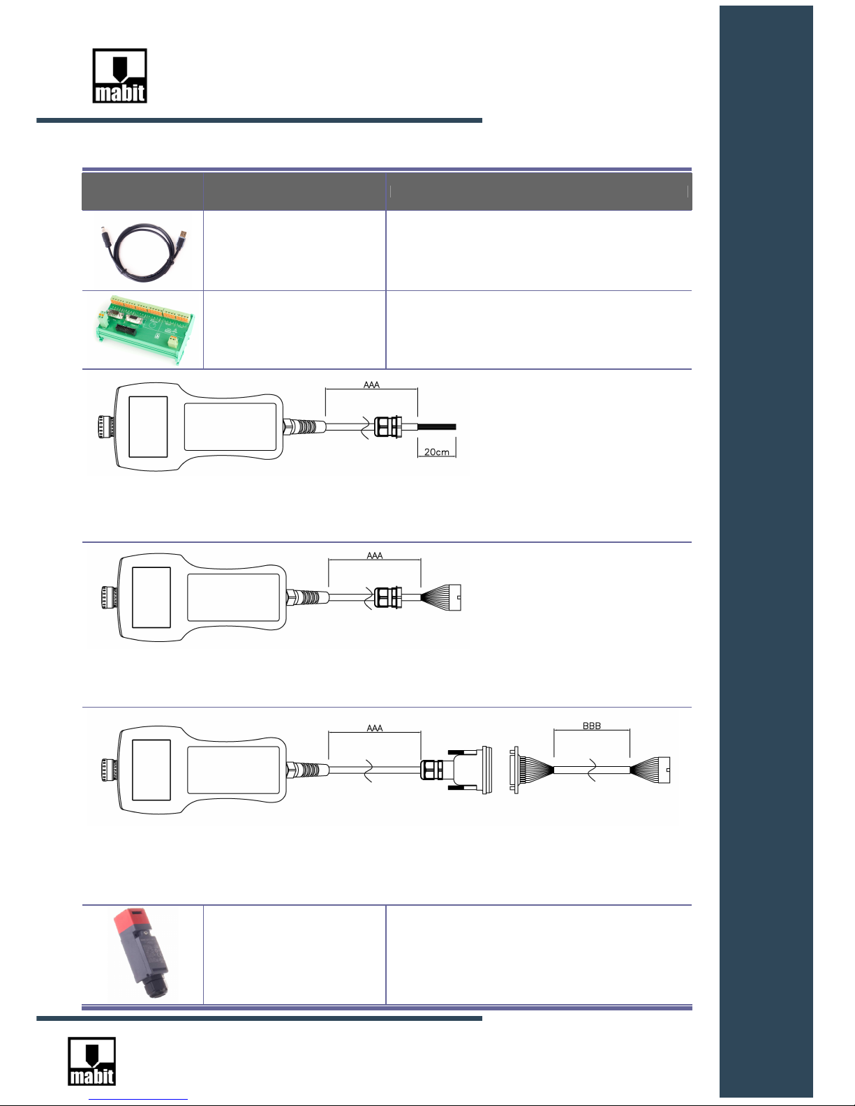
3.5. Technical data of USB cable for programming SC5-PROG...........................................- 14 -
3.6. Technical data of interface separating signals SC5-INT................................................- 15 -
3.7. Technical data of SC5-CAB cables................................................................................- 16 -
3.8. Technical data of automatic work mode switch SC5-AUT .............................................- 17 -
4. Wiring....................................................................................................................................- 18 -
4.1. Connecting the cable to SmartControl...........................................................................- 18 -
4.2. Connection to controller/ machine..................................................................................- 22 -
4.2.1 Connection with SC5-CAB-N-AAA cable..................................................................- 22 -
4.2.2 Connection with SC5-CAB-S-AAA cable..................................................................- 23 -
4.2.3. Connection with SC5-CAB-D-AAA cable.................................................................- 23 -
4.2.4 Connection of SC5-INT Interface. ............................................................................- 24 -
4.3. Connection of automatic machine work mode switch SC5-AUT....................................- 26 -
4.3.1 SC5-AUT connection pattern.......................................................................................- 26 -
4.3.2 Example of safety system with automatic work mode switch..................................- 26 -
5. Installation.............................................................................................................................- 27 -
5.1. SmartControl – dimensions............................................................................................- 27 -
5.2. SmartControl – methods of fixing on the machine .........................................................- 28 -
List of contents

- 3 -
MAB 2010280101 EN V2.2
www.mabit.pl info@mabit.pl
5.2.1 Using a hook.............................................................................................................- 28 -
5.2.2 Using a magnet ........................................................................................................- 29 -
5.2.3 Using automatic machine work mode switch SC5-AUT ...........................................- 29 -
5.3. SC5-INT interface – dimensions....................................................................................- 30 -
5.4. Keyboard – individual key labels – printout....................................................................- 31 -
5.5. Keyboard – individual keyboard labels – assembly .......................................................- 32 -
6. Start-up.................................................................................................................................- 33 -
6.1. SmartControl Software installation.................................................................................- 33 -
6.2. USB drivers installation..................................................................................................- 36 -
6.3. Connecting to PC for programming................................................................................- 40 -
7. Entering variables from the keyboard (edit mode)................................................................- 41 -
7.1. Entering a number – version without hand wheel..........................................................- 43 -
7.2. Entering a number – version with ENC hand wheel.......................................................- 45 -
7.3. Choosing a text variable from text list............................................................................- 45 -
8. Menu operation.....................................................................................................................- 46 -
8.1. Choosing language........................................................................................................- 47 -
8.2. Turning on / off keyboard sounds...................................................................................- 48 -
8.3. Setting display contrast..................................................................................................- 49 -
9. Troubleshooting....................................................................................................................- 50 -
9.1. Communication..............................................................................................................- 50 -
9.2. Error information ............................................................................................................- 52 -
10. Copyrights...........................................................................................................................- 53 -
11. Guarantee conditions..........................................................................................................- 53 -

- 4 -
MAB 2010280101 EN V2.2
www.mabit.pl info@mabit.pl
1. Safety information
Read this instruction manual carefully and inspect the device in order to
become thoroughly familiar with it prior to its installation and operation.
The following may appear in this document or device to warn of potential
hazards or to draw attention to clarifying information.
Electrical devices should be installed and maintained by qualified personnel
only. Mabit company is not responsible for any consequences of using this
material.
This manual is not intended for inexperienced people.
WARRNING
INFORMATION

- 5 -
MAB 2010280101 EN V2.2
www.mabit.pl info@mabit.pl
2. Introduction
2.1. Main features
SmartControl is a fully universal, programmable, portable HMI type device. Adapted for use with
PLC and CNC controllers.
SmartControl is equipped with:
- Emergency off switch or Emergency stop
- Three-stage enabling switch
- Automatic work mode switch
All comply with safety standards:
ISO 13849-1 – PL e
EN954-1 – cat. 4
IEC 61508 - IL 3
Universal keyboard with 17/13 free programmable keys.
Labels inserted into the keyboard (printed on plain, office paper on a printer) enable custom
labeling of each key.
Hand Wheel with resolution 50 PPR and configurable outputs
Friendly visualization software for quick creation of screen pages,
variable fields and configurations (free)
- 4096 screen pages
- up to 64 variables on the page
- a table of 2048 texts with 4 switchable languages
- export / import of the table of texts to a csv or txt file
- built-in simulation
- programming via USB
- numeric variables in different formats
SmartControl Software Manual is available on our website:
www.mabit.pl or after installing the software as HELP option.
IP65
ISO 13849-1
EN954-1
IEC 61508

- 6 -
MAB 2010280101 EN V2.2
www.mabit.pl info@mabit.pl
2.2. Ordering
Appearance Catalog number Emergency off
switch/ stop Enabling
switch Hand wheel Mounting type
SC5-R-E-A
Red
( emergency off
switch ) YES NO Key for automatic work
mode switch ( switch
ordered separately )
SC5-R-E-M
Red
( emergency off
switch ) YES NO
Hook with magnet
SC5-R-E-W
Red
( emergency off
switch ) YES NO
Hook without magnet
SC5-R-N-M
Red
( emergency off
switch ) NO NO
Hook with magnet
SC5-R-N-W
Red
( emergency off
switch ) NO NO
Hook without magnet
SC5-G-E-A
Grey
( emergency stop ) YES NO
Key for automatic work
mode switch ( switch
ordered separately )
SC5-G-E-M
Grey
( emergency stop ) YES NO
Hook with magnet
SC5-G-E-W
Grey
( emergency stop ) YES NO
Hook without magnet
SC5-G-N-M
Grey
( emergency stop ) NO NO
Hook with magnet
SC5-G-N-W
Grey
( emergency stop ) NO NO
Hook without magnet

- 7 -
MAB 2010280101 EN V2.2
www.mabit.pl info@mabit.pl
Appearance Catalog number Emergency off
switch/ stop Enabling
switch Hand wheel Mounting type
SC5-R-E-A-ENC
Red
( emergency off
switch ) YES YES Key for automatic work
mode switch ( switch
ordered separately )
SC5-R-E-M-ENC
Red
( emergency off
switch ) YES YES
Hook with magnet
SC5-R-E-W-ENC
Red
( emergency off
switch ) YES YES
Hook without magnet
SC5-R-N-M-ENC
Red
( emergency off
switch ) NO YES
Hook with magnet
SC5-R-N-W-ENC
Red
( emergency off
switch ) NO YES
Hook without magnet
SC5-G-E-A-ENC
Grey
( emergency stop ) YES YES
Key for automatic work
mode switch ( switch
ordered separately )
SC5-G-E-M-ENC
Grey
( emergency stop ) YES YES
Hook with magnet
SC5-G-E-W-ENC
Grey
( emergency stop ) YES YES
Hook without magnet
SC5-G-N-M-ENC
Grey
( emergency stop ) NO YES
Hook with magnet
SC5-G-N-W-ENC
Grey
( emergency stop ) NO YES
Hook without magnet
The above pictures are available in 3D on our website www.mabit.pl

- 8 -
MAB 2010280101 EN V2.2
www.mabit.pl info@mabit.pl
Accessories:
Appearance Catalog number Description
SC5-PROG USB cable for programming
SC5-INT Interface separating signals and power supply in the switch
cabinet, for installation on DIN rail
SC5-CAB-N-AAA
Cable for connecting SmartControl with the machine, without plugs ended with free wires with cable gland ( AAA is length in cm )
[ 1500 = 15m ]
SC5-CAB-S-AAA
Cable for connecting SmartControl with the machine, with 26pin plug for connecting SC5-INT interface and with cable gland
(AAA is length in cm ) [ 1500 = 15m ]
SC5-CAB-D-AAA-BBB
Two-piece cable for connecting SmartControl with the machine, with IP67 D-sub plug, socket for installation in the switch cabinet
and 26pin plug for connecting SC5-INT interface (AAA is length in cm from SmartControl to the socket, BBB length in cm from
the socket to the SC5-INT interface) [ 1500 = 15m ]
SC5-AUT
Automatic machine work mode switch (the switch is
permanently fixed outside the danger zone, after taking
SmartControl off the switch, the machine switches to manual
control whereby using the enabling switch is necessary e.g. for
starting drives ). It has the cable gland.

- 9 -
MAB 2010280101 EN V2.2
www.mabit.pl info@mabit.pl
2.3. Nameplate
MODEL = Catalog no.
Always quote the serial number in queries for
technical support and possible complaints.
S/N = Serial Number, unique number of particular copy

- 10 -
MAB 2010280101 EN V2.2
www.mabit.pl info@mabit.pl
3. Technical data
3.1. Technical data of SmartControl
SC5-R-E-A
SC5-R-E-A- ENC
SC5-G-E-A
SC5-G-E-A-ENC
SC5-R-E-M
SC5-R-E-M-ENC
SC5-G-E-M
SC5-G-E-M-ENC
SC5-R-E-W
SC5-R-E-W-ENC
SC5-G-E-W
SC5-G-E-W-ENC
SC5-R-N-M
SC5-R-N-M-ENC
SC5-G-N-M
SC5-G-N-M-ENC
SC5-R-N-W
SC5-R-N-W-ENC
SC5-G-N-W
SC5-G-N-W-ENC
Rated Power Voltage 24V DC
Allowable Voltage Range 10 do 40V DC
Maximum Input Current 100mA (10V DC) 60mA (24V DC)
Maximum Power
Consumption 1,5 W ( 24V DC )
Allowable Momentary
Power Interruption 10ms ( przy 24V DC )
Dielectric Strength 1000V AC, 1 minute
Insulation Resistance Minimum 10MΩ
Inrush Current Maximum 10A (24V DC)
Power Supply Wire AWG26 – AWG24 0,14mm² – 0,5mm²
Operating Temperature 5 do 40°C
Storage Temperature -40 do +70°C
Relative Humidity 10 do 95% (IEC61131-2) no condensation
Altitude 0 do 2000m
Pollution Degree 3
Degree of Protection IP65 (IEC60529)
Signal Wire AWG26 – AWG24 0,14mm² – 0,5mm²
Vibration Resistance 5 do 8,4Hz - amplitude 3,5mm , 8,4 do 150Hz acceleration 1G (IEC61131-2)
Shock Resistance 15G, 11ms, a half of sinusoid, in each of three perpendicular axes
Interfaces 1 – RS232 2 - RS485/422/485 4W
Communications protocols
BALDOR HCP1 (MASTER)
BALDOR HCP2 (MASTER)
FATEK PROTOCOL
MODBUS RTU (MASTER)
MODBUS RTU (SLAVE)
Chosen protocol on request
Transmission speed
(baud) 19200, 38400, 57600, 115200
Display 4 x 16 characters, blue background, white characters
Number of screen pages 4096
Number of texts 2048 x 4 languages
Number of variables per
page max 64
Weight (without cord) 530g 550g 525g 545g 520g
Weight (without cord)
Hand wheel version (ENC)
590g
610g 585g 605g 580g

- 11 -
MAB 2010280101 EN V2.2
www.mabit.pl info@mabit.pl
3.2. Technical data of Hand wheel
SC5-.-.-.-ENC
Resolution 50 PPR ( with recognition of each edge - x4 )
Work mode 1-
Phase quadrature A/B 2-STEP/DIR 3-UP/DOWN ( jumper-selectable)
Output types 1- Line driver RS422 2- 5V (push-pull) 3- 24V (push-pull) ( jumper-selectable )
After setting of jumpers, switch OFF and ON
SmartControl

- 12 -
MAB 2010280101 EN V2.2
www.mabit.pl info@mabit.pl
3.3. Technical data of butli-in emergency off switch/stop (IDEC)
SC5-R-E-A SC5-R-E-A-ENC
SC5-R-E-M SC5-R-E-M-ENC
SC5-R-E-W SC5-R-E-W-ENC
SC5-R-N-M SC5-R-N-M-ENC
SC5-R-N-W SC5-R-N-W-ENC
SC5-G-E-A SC5-G-E-A-ENC
SC5-G-E-M SC5-G-E-M-ENC
SC5-G-E-W SC5-G-E-W-ENC
SC5-G-N-M SC5-G-N-M-ENC
SC5-G-N-W SC5-G-N-W-ENC
Emergency off switch /
stop (IDEC)– catalog no.
of the manufacturer XA1E-BV3U02R
XA1E-BV3U02N
Applicable Standards
UL508
CSA C22.2 No.14
IEC 60947-5-1
EN 60947-5-1
IEC 60947-5-5
EN 60947-5-5
JIS C8201-5-1
UL508
CSA C22.2 No.14
IEC 60947-5-1
EN 60947-5-1
JIS C8201-5-1
Applicable Standards for
Use
ISO 12100 / EN292
IEC 60204-1 / EN 60204-1
ISO 13849-1
EN954-1
IEC 61508
Key diameter 29mm
Contact Resistance 50mΩmax
Impulse Withstand
Voltage 2,5 kV
Operating Frequency 900 / hour max
Durability Mechanical - 250 000
Electrical – 100 000
250 000 (24V DC, 100mA)
Recommended circuit fuse
of emergency off
switch/stop 250V/10A ( Type aM IEC 60269-1/IEC 60269-2 )
Conditional Short-circuit
Current 1000A
Rated Voltage 24V DC
Number of contacts 2NC
Maximum operating
current 2A – resistive load 1A – inductive load

- 13 -
MAB 2010280101 EN V2.2
www.mabit.pl info@mabit.pl
3.4. Technical data of butli-in enabling switch (IDEC)
SC5-R-E-A SC5-R-E-A-ENC
SC5-R-E-M SC5-R-E-M-ENC
SC5-R-E-W SC5-R-E-W-ENC
SC5-G-E-A SC5-G-E-A-ENC
SC5-G-E-M SC5-G-E-M-ENC
SC5-G-E-W SC5-G-E-W-ENC
Enabling switch (IDEC) –
catalog no. of the
manufacturer HE5B-M2PY
Applicable Standards
IEC 60947-5-1
EN 60947-5-1
UL508
CSA C22.2, No. 14
JIS C8201-5-1
Applicable Standards for
Use
ISO 12100 / EN292
IEC 60204-1 / EN 60204-1
ISO 11161 / prEN 11161
ISO 10218 / EN 775,
ANSI/RIA R15.06,
ANSI B11.19
ISO 13849-1
EN954-1
IEC 61508
Contact Resistance 50mΩmax
Impulse Withstand
Voltage 1,5 kV
Operating Frequency 1200 / hours max
Mechanical Durability Position 1 – 2 – 1 : 1000 000 operations minimum
Position 1 – 2 – 3 - 1 : 100 000 operations minimum
Electrical Durability 100 000 operations minimum
Recommended circuit fuse
of approval key 250V/10A fast
Conditional Short-circuit
Current 50A
Rated Voltage 24V DC
Number of contacts 2NO
Maximum operating
current 1A – resistive load 0,7A – inductive load

- 14 -
MAB 2010280101 EN V2.2
www.mabit.pl info@mabit.pl
3.5. Technical data of USB cable for programming SC5-PROG
SC5-PROG
Length of cable 175cm
Plug PC side USB Type A
Plug SmartControl side M8, MALE 4 pin

- 15 -
MAB 2010280101 EN V2.2
www.mabit.pl info@mabit.pl
3.6. Technical data of interface separating signals SC5-INT
SC5-INT
Installation DIN rail
Height 92,5mm
Width 155mm
Depth Max 72,5mm
Section of wires for spring clips AWG22 – AWG16 0,34mm² – 1,5mm²
Section of wires for 24VDC power
supply plug AWG26 – AWG12 0,34mm² – 2,5mm²
Socket for connecting SmartControl Male, 26 pin, type IDC ( see cables SC5-CAB…. )
Socket RS23 no.1 Male, 9 pin, D-sub
Socket RS23 no.2 Female, 9 pin, D-sub

- 16 -
MAB 2010280101 EN V2.2
www.mabit.pl info@mabit.pl
3.7. Technical data of SC5-CAB cables
SC5-CAB-N-AAA SC5-CAB-S-AAA SC5-CAB-D-AAA-BBB
Type of cable LiYCY-P 12 x 2 x 0,14 mm²
Strand transverse section AWG26 0,14mm²
External diameter 8,5mm
Shield YES
Wire resistance 0,276 Ω/ m ( for one loop ) max
Resistance for oil, grease
Resistant with sporadic contact
Condition of cable end
from SmartControl
Cable installed and connected to SmartControl according to the schematic in the instruction
manual
Cable splitting NO NIE
Cable split in two parts with
AAA and BBB lenghts:
The first part connected to
SmartControl from one side,
from the other to the D-SUB
hermetic connector.
The second part of the cable
ended with D-SUB hermetic
seal for installation in the
switch cabinet from one side,
and from the other with 26 pin
plug for SC5-INT distributor
Cable enables easily
disconnection of SmartControl
from the machine ( e.g. for
transport )
Condition of cable end
from SmartControl Cable ended with free wires of
20 cm length
Cable ended with 26 pin plug
adjusted to SC5-INT
distributor
Cable ends with 26 pin plug
adjusted to SC5-INT
distributor
Cable gland SKINTOP M20x1.5 Black with cap. Installed on the cable None, the function of gland is
performed by D-SUB hermetic
seal
Weight about 90g / m

- 17 -
MAB 2010280101 EN V2.2
www.mabit.pl info@mabit.pl
3.8. Technical data of automatic work mode switch SC5-AUT
SC5-AUT
Automatic work mode
switch (IDEC) – catalog
no. of the manufacturer HS5D-12RNM
Applicable Standards
ISO14119
EN1088
IEC60947-5-1
EN60947-5-1
GS-ET-15 UL508
CSA C22.2 No. 14,
GB14048.5
Applicable Standards for
Use
ISO 12100 / EN292
IEC 60204-1 / EN 60204-1
ISO 13849-1
EN954-1
IEC 61508
Operating Temperature -30 do +70
Storage Temperature -40 do +80
Relative Humidity 45 do 85% ( no condensation )
Rated Insulation Voltage 300V
Degree of Protection IP67 (IEC60529)
Actuator Operating Speed 0,05 do 1,0 m/s
Direct Opening Travel 10mm minimum
Direct Opening Force 50N minimum
Termal Current 10A
Contacts 2NC – 1NO
Strand transverse section 20 do 16 AWG 0,5 do 1 mm²
Rated Voltage Contact
Ratings Rated
Voltage Contact
Ratings
AC AC
AC
DC DC
Contact Ratings
DC
Minimum Applicable Load 5V AC/DC, 1mA
Operating Frequency 900 / hour
Mechanical Durability 1000 000 operations minimum
Electrical Durability 100 000 operations minimum ( AC-12 250V, 6A )
1000 000 operations minimum ( 24V AC/DC, 100mA )
( with frequency of operations of 900/ hour)
Cable diameter 7 – 13mm
Cable gland Size of installation wrench 25mm
Weight about 80g

- 18 -
MAB 2010280101 EN V2.2
www.mabit.pl info@mabit.pl
4. Wiring
4.1. Connecting the cable to SmartControl
To get to connecting clamps, follow the steps:
1. Unscrew 6 screws located at the bottom of
the casing.
2. Disconnect the plug of the ribbon wire from
the socket.

- 19 -
MAB 2010280101 EN V2.2
www.mabit.pl info@mabit.pl
Terminal plate with spring clips:
When ordering SmartControl with any SC5-CAB ... cable, it will be already
connected to SmartControl, as shown in the table below.

- 20 -
MAB 2010280101 EN V2.2
www.mabit.pl info@mabit.pl
WIRE COLOUR (PAIR) Clamp
no. DESCRIPTION
RED 1
Power supply +24VDC
BLUE
2
Power supply 0VDC ( -24VDC )
GRAY
3
Rx- signal reception for RS422 or RS485 four-wire in
terface
PINK 4
Rx+ signal reception for RS422 or RS485 four-
wire interface
BLACK 5
Tx- signal transmission for RS422 or RS485 four-wire interface or DATA-
signal for RS485 two-wire inte
rface
VIOLET 6
Tx+ signal transmission for RS422 or RS485 four-wire interface or DATA+
signal for RS485 two-
wire interface
YELLOW 7
GND for RS232 interface
GREEN 8
Rxd signal reception for RS232 interface
WHITE 7
GND for RS232 interface
BROWN 9
Txd signal transmission for RS232 interface
GRAY PINK 10
NO contact no. 1 of Approval key
RED BLUE 11
NO contact no. 1 of Approval key
WHITE PINK 12
NO contact no. 2 of Approval key
PINK BROWN 13
NO contact no. 2 of Approval key
WHITE YELLOW 14
NC contact no. 1 of Emergency off switch/ Emergency stop
YELLOW BROWN 15
NC contact no. 1 of Emergency off switch/ Emergency stop
WHITE GRAY 16
NC contact no. 2 of Emergency off switch/ Emergency stop
GRAY BROWN 17
NC contact no. 2 of Emergency off switch/ Emergency stop
WHITE BLUE 18
/A signal RS422 of hand wheel
BROWN BLUE 19
A signal RS422 of hand wheel
WHITE RED 20
/B signal RS422 of hand wheel
BROWN RED 21
B signal RS422 of hand wheel
WHITE GREEN 22
A signal ( 0-5V or 0-24V ) of hand wheel ( GND – pin no. 2 )
BROWN GREEN 23
B signal ( 0-5V or 0-24V ) of hand wheel ( GND – pin no. 2 )
Table of contents