G6000T Gyro Set Up Instructions
Transmitter Set Up
1. Set rudder travel adjust on the transmitter to 150%.
2. Set
rudder sub trim to 0%.
3. Make sure
mechanical and digital rudder trims are set
to neutral.
4. Set the
rudder trim rate to 1(PCM10X, X3810ADT).
5. Turn
off all tail rotor mixing.
6. Plug gyro gain lead into AUX3 (PCM10) or AUX2 (X3810).
7. Plug select lead into AUX2 (PCM10) or GEAR (X3810).
8. Turn the receiver on.
9. Ensure tail rotor (rudder) is moving in the correct direction
and reverse if necessary.
10. Set the travel adjust of Select(AUX2/GEAR) to 50% in the
normal position and 0 to -100% in the low position. This
allows heading hold to be disabled when the
Select(AUX2/GEAR) switch is in the low position, but
leaves heading hold enabled in the high position.
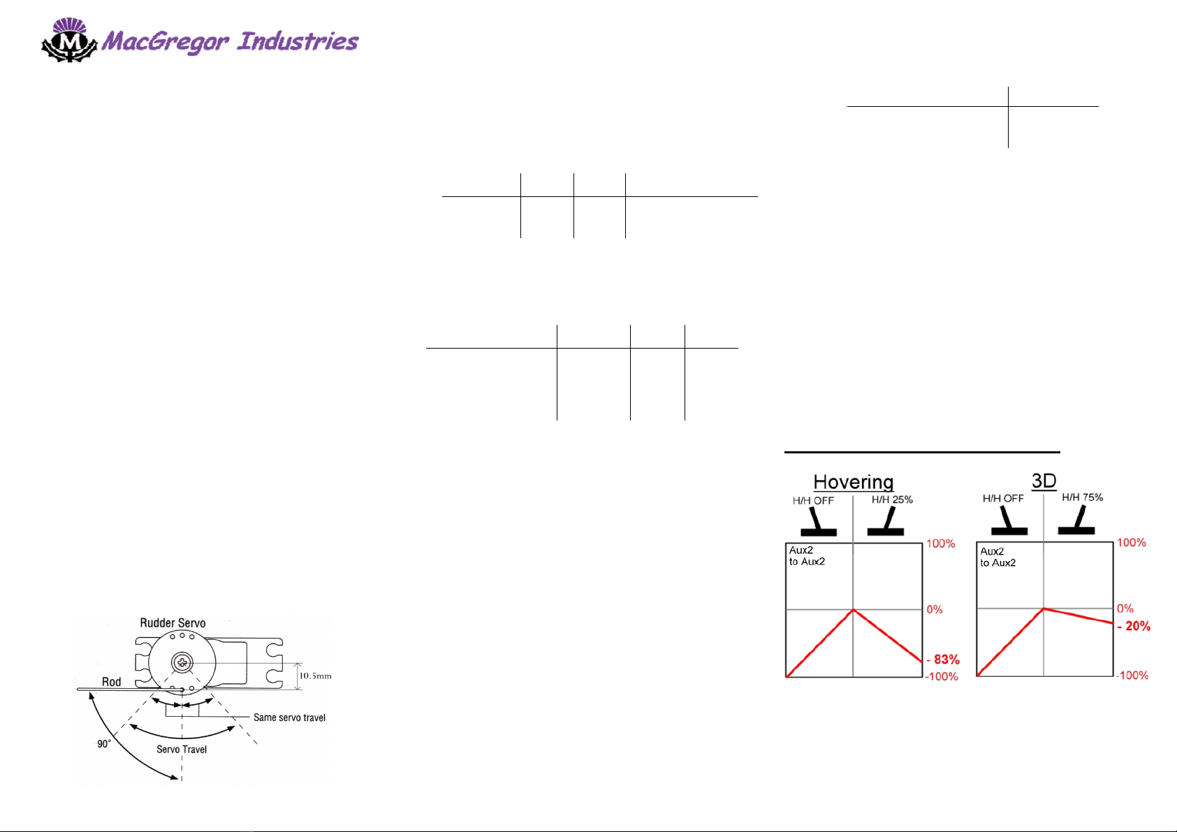
11. Ensure that the servo horn is at 90º to the tail rotor push
rod when heading hold is off. Adjust mechanically if
necessary. (Use hole approx 10.5mm out on servo
disc.)
12. Ensure the
gyro is working in the correct
direction, reverse if necessary by using the
REV switch on the gyro amplifier.
13. Using the transmitter adjust the gyro gain
to be 80% on the high side (hovering) and
50% on the low side (aerobatics).
14. Now adjust the tail rotor rates and expo to
the following:
Purpose Rate Expo Use
Normal 60% 40% Hovering
Stunt1 100% 60% 540º Stall Turn
Stunt2 60% 60% Loops, Rolls, etc
15. Check the heading hold effectiveness by
adjusting the Select(AUX2/GEAR) travel
adjust and observing the change of lights
on the gyro amplifier:
Travel Adjust ON/OFF BW1 BW2
100% Green Green Green
75% Green Red Green
50% Green Green Red
25% Green Red Red
0~-100% Red Red Red
Set the travel adjust so that when tail lock
is on you are running 50% tail lock
effectiveness (Green,Green,Red).
16. Ensure the CTL and Gain switches are in
the low position on the gyro amplifier (left
side)
Model Set Up
1. In heading hold mode, adjust the sub trim
of the transmitter to the point where the tail
rotor does not drift from centre.
2. Out of heading hold mode (rate mode) use
the trim pot on the amplifier so that the
neutral change on the tail rotor servo is as
small as possible when you change in and
out of heading hold. Fly the model in
heading hold (50% effectiveness) and
adjust the sub trim on the transmitter until
the model hovers straight.
3. Switch to non heading hold (rate mode),
and adjust the linkage on the model until it
hovers straight.
Advanced Set Up
Now adjust the heading hold effectiveness to suit your preferred
flying style:
Purpose Setting
3D Flight 75%
Normal Aerobatics 0% or 50%
Hovering 25%
You can have the your transmitter set so that in different flight
modes you can automatically run different heading hold
effectiveness without having to flick any switches.
To do this you need to create a mix that mixes the Select switch (in
this case AUX2 for PCM10 users, otherwise gear for X-3810 etc.) to
its self. Then you need to adjust the mix so that when the switch is
in the normal flying position you get the amount of heading hold you
require for a desired flight mode. Then only have this mix activated
on that flight mode. You can then create several of these mixes, a
different one active on each flight mode, to automatically adjust the
heading hold.
By doing this when you flick the Select switch you will always be
able to turn off heading hold, but with it in the normal flying position
you will have varying amounts of heading hold effectiveness
depending on what flight mode you are in.
Typical setting for hovering and 3D flight: