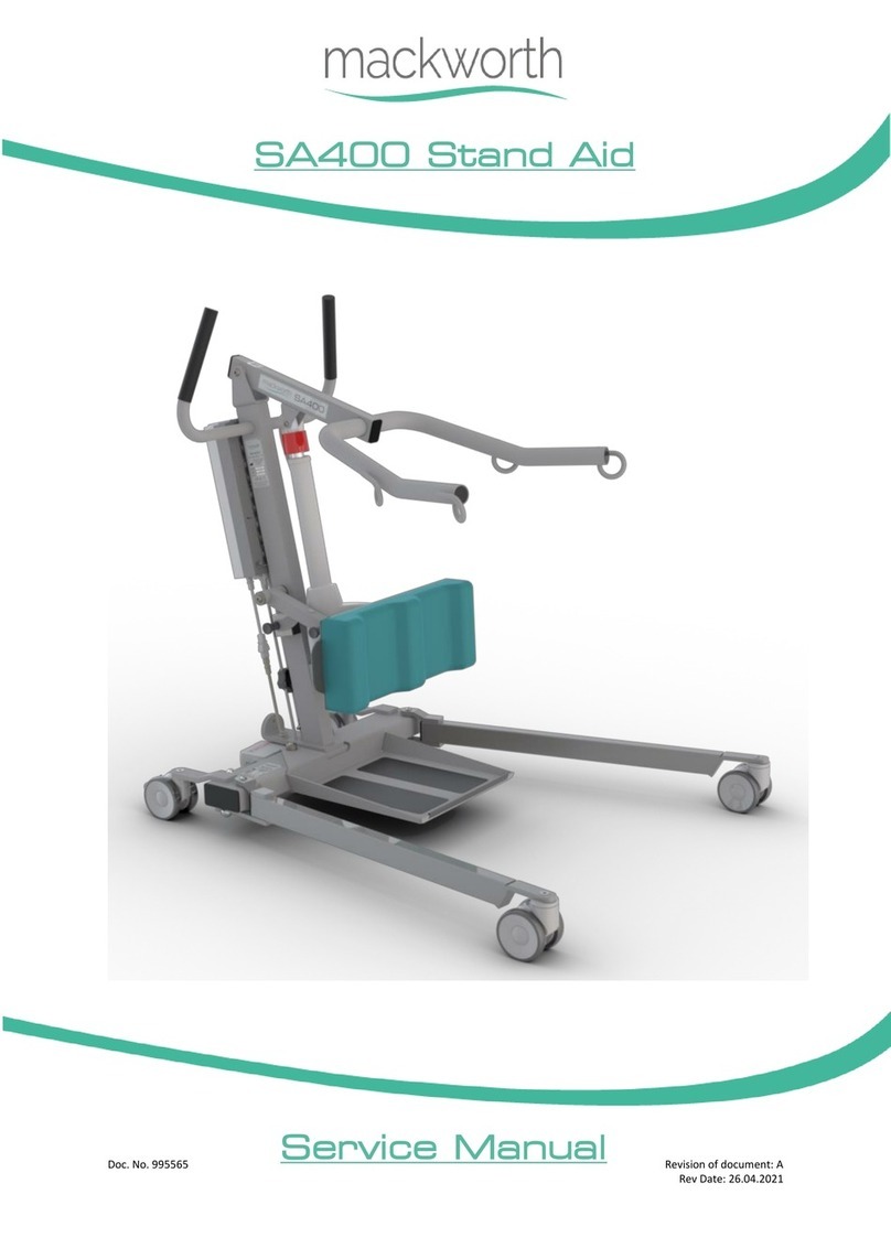
Mackworth Raiser User manual

Doc No. 999061 Revision of document: A
Revision Date: 19.04.21
Raiser Transfer Aid
User Manual

999061 – Revision A Page | 2 of 28
CONTENTS
1.0 Safety Instructions and Warnings ...................................................................................................................................................... 3
1.1 Introduction ................................................................................................................................................................................. 3
1.2 Manufacture ................................................................................................................................................................................ 3
1.3 European Authorised Representative............................................................................................................................................ 3
1.4 Symbols Used ............................................................................................................................................................................... 4
1.5 Contraindications/Limitations....................................................................................................................................................... 5
1.6 Intended Use................................................................................................................................................................................ 5
1.7 Warning Notes ............................................................................................................................................................................. 6
1.8 Operating Environment ................................................................................................................................................................ 6
2.0 Components / Key Parts.................................................................................................................................................................... 7
3.0 Assembly Instructions ....................................................................................................................................................................... 8
3.1 Unpacking .................................................................................................................................................................................... 8
3.2 Unboxing Transfer Aid .................................................................................................................................................................. 8
3.3 Transfer Aid Assembly .................................................................................................................................................................. 9
4.0 Frequenly Used Functions ................................................................................................................................................................. 9
4.1 Adjusting Knee/shin Pad (Single Knee Pad) .................................................................................................................................... 9
4.2 Adjusting Knee/shin Pad (Double Knee Pad) .................................................................................................................................10
4.3 Applying the brakes ....................................................................................................................................................................10
5.0 Operating Principles.........................................................................................................................................................................11
5.1 Standing a user who requires no assistance..................................................................................................................................11
5.2 Standing a user who requires assistance with optional Ladder belt. .............................................................................................11
5.3 Standing a user who requires assistance with the optional safety belt..........................................................................................12
5.4 Compatible Belt Types .................................................................................................................................................................13
6.0 Technical Specification .....................................................................................................................................................................14
6.1 Raiser Dimensions – Single Knee Pad............................................................................................................................................14
6.2 Raiser Dimensions – Double Knee Pad.........................................................................................................................................15
6.3 Specifications ..............................................................................................................................................................................16
6.4 Standards Applied .......................................................................................................................................................................16
7.0 Environmental - Storage and Operating Conditions ...........................................................................................................................17
7.1 Normal operating conditions........................................................................................................................................................17
7.2 Shipping and storage conditions...................................................................................................................................................17
8.0 Disposal ...........................................................................................................................................................................................17
9.0 Fault Finding ....................................................................................................................................................................................18
10.0 General Inspection, Maintanance and Cleaning.................................................................................................................................18
10.1 Service....................................................................................................................................................................................18
10.2 Inspection...............................................................................................................................................................................19
10.3 Cleaning..................................................................................................................................................................................20
10.3.1 General cleaning ................................................................................................................................................................20
10.3.2 Disinfecting (if necessary) ...................................................................................................................................................20
11.0 Warranty .........................................................................................................................................................................................21
12.0 Service Record History......................................................................................................................................................................22
999061 – Revision A Page | 3 of 28
1.0 SAFETY INSTRUCTIONS AND WARNINGS
1.1 Introduction
As transferring a person presents a potential risk, the information in this manual is important to your safety.
Please read and understand this manual in its entirety before using your Raiser Transfer Aid.
Should any questions arise from reviewing this manual, contact your local authorised representative.
The information in this manual is important for the safety of anyone near the Raiser Transfer Aid and must be read and
understood to help prevent injuries. It is also crucial to the proper operation and maintenance of the Raiser transfer aid.
Failure to comply with warnings in this manual may result in; injury to the operator and/or client and/or damage to the Transfer
Aid or related components.
If, during the use of this device or as a result of its use a serious incident has occurred, please report it to the manufacturer and
to your national authority.
Store this manual with the documents included with the Transfer Aid. Contents of this manual are subject to change without
prior written notice.
Unauthorised modifications on any Prism Medical UK product may affect its safety. The manufacturer will not be
held responsible for any accident, incident or deficiencies of performance that occur as a result of any unauthorised
modification to its products.
Do not attempt to use this equipment without first understanding the contents of this manual.
1.2 Manufacture
The Transfer Aid is manufactured at the address below:
Prism Medical UK
Unit 1, Tir Llwyd Industrial Estate, St Asaph Avenue, Kinmel Bay, Conwy, LL18 5JZ
Telephone number: 01924 840100
1.3 European Authorised Representative
The address of the European Authorised Representative for this product:
European Healthcare & Device Solutions (Ireland) Ltd.
Stratton House, Bishopstown Road,
Cork, Ireland.
T12 Y9TC.
Telephone number: +353(86)2280846

999061 – Revision A Page | 4 of 28
1.4 Symbols Used
The Table below includes all Symbols from BS EN ISO 15223-1:2016 that can be found in this Manual and on the Product and
what they represent. Refer back to this Table when you are unsure of what a symbol represents.
Consult instructions before use
Caution – see instructions for use
Manufacturer
Safe Working Load represents the
maximum load rated for safe
operation
Packaging indicator – This way up
Date of manufacture
Serial number
Packaging indicator – Keep dry
Please observe local laws on recycling
For internal use only
Temperature range
Degree of protection provided by
enclosure.
N1: Ingress of particles
N2: Ingress of water
Humidity range
Medical Device
Catalogue number
European Authorised Representative
Table 1

999061 – Revision A Page | 5 of 28
1.5 Contraindications/Limitations
There are no known “contraindications” associated with the usage of the Raiser Transfer Aid, provided they are used as per
manufacturer’s recommendations and guidelines. However, it is recommended that a client specific assessment is completed by
a trained and knowledgeable health care professional to determine the method of transfer.
Prism Medical UK does not recommend a required number of care givers for the use of our products. This information and
recommendation can only be provided after a thorough personalised, case specific assessment, as there are many factors that
can influence these decisions.
1.6 Intended Use
For internal use only.
The Mackworth Raiser is a sit to stand platform, which is designed to provide an active, safe and comfortable transfer of the
user. It is ideal for short distance transfers, such as to/from bed to chair.
Its versatility allows use with wheelchairs, toilet and shower chairs. Soft and wide padding in the leg support improves stability,
and the sturdy handle offers many grip options for both the user and the carer.
The rear wheels with independent locking manual brakes, makes it easy for a carer to manoeuvre, and provides maximum
stability and safety for the user.
The Mackworth Raiser has a safe working load of 160 kg, this load must not be exceeded.
The device is used under instruction, and the operation of the aid is undertaken by a trained carer.
A risk assessment must be performed before using any other manufactured Transfer Aid, to ensure safe use can be
established.
The belt(s) is a specially designed fabric accessory that attaches to the Transfer Aid by means of the hooks on the rear face of the
handle, this holds and aids an individual while the transfer takes place. The sling is supplied separately from the Transfer Aid at
the initial time of purchase.
If additional accessories have been supplied with the Transfer aid, refer to the instructions included with those items.
The Transfer Aid:
•Helps to assist a user with sit to stand transfers
•Maximum user weight: 160 kg
•Padded leg support for added comfort
•Multiple grip options for both user and carer
•Raiser Strap & Safety Belt available to enable a carer to assist a user to their feet
•Independent locking rear brakes
•The Raiser is intended to be installed on a flat and levelled surface prior to use.
•The Transfer Aid must be installed only by persons authorised by Prism Medical UK or who have the rights to install and
commission the Transfer Aid safe for use.
•Under no circumstance should the Raiser be put in control of a person who has not been properly trained in the use
and care of this equipment. Failure to adhere to this warning may result in serious injury to the operator, and / or the
individual being transferred.
•In facilities where more than one operator will be responsible for using the Transfer Aid, it is imperative that all such
members be trained on the Raiser prior to use. A training program should be established by the facility to acquaint new
operators with this equipment.
•The Raiser Transfer Aid, and associated belts are not toys. Do not use it for unsafe practices. Do not allow children to
play with the Aid or any of its components. The Raiser should not be used for any practice except its intended use.

999061 – Revision A Page | 6 of 28
•Your guarantee is void if persons unauthorised by Prism Medical UK perform work on the Transfer Aid.
•To maintain optimum function, the Raiser should be inspected and maintained on a regular basis. See section ‘General
Inspection, Maintenance and Cleaning’ within this user manual.
•The Raiser and belt(s) are intended only for transferring of a person. Prism Medical UK will not be responsible for any
damage caused by the misuse, neglect or purposeful destruction of the Unit, and/or its associated components.
•In areas where children are prone to be present, be vigilant when carrying out a transfer.
•Any accessories used with the Raiser including belt(s), should be checked to ensure that they are in good working order.
Check for signs of wear to each component prior to use. Report any unusual wear to your local authorized dealer.
•The Raiser and its associated parts are certified to a maximum load of 160kg. Do not exceed the maximum rated load of
any of the components.
•Ensure that a clear space is maintained around the Transfer Aid. Before performing a transfer check for and move all
obstacles out of the way.
•Protecting the people present, visually monitor the belt loop connection points during transfer stages, so the belt
remains firmly attached to the hooks on the rear face of the Raiser.
•To reduce the risk of unintended use, when the Raiser is not in use remove the Belt from the product to prevent
entrapment or strangulation should the device be tampered with.
•Between Transfer Aid and Belt, the lowest maximum load shall always be used.
You may need to seek specialist advice on how to assist some people with specific moving and handling needs.
Sources of advice include, but is not limited to, professional bodies and organisations, occupational therapist,
physiotherapists, manual handling advisers and ergonomist with experience in health and social care.
1.7 Warning Notes
Your Raiser Transfer Aid has been manufactured and tested to exceed BS EN 12182:2012. This does not mean that it
can be used without care. ALL OPERATORS should have read the operating instructions and appreciate this warning
section.
1. ALL Transfer Aids are less stable on sloping surfaces. A 5-degree slope is the maximum permitted and then only with
great care.
2. ALL Transfer Aids are dangerous to the person being transferred when used recklessly or pushed at speed.
3. ALL Transfer Aids are less stable when the load is moving.
4. Use of this equipment adjacent to or stacked with other equipment should be avoided, as it could result in improper
operation. If such use is necessary, this equipment and the other equipment should be observed to verify that they are
operating normally.
1.8 Operating Environment
The Raiser Transfer Aid is intended for use within the professional health care facility environment as well as the home health
care environment. The Transfer Aid is not suitable for any other environment or special environments.
The Transfer Aid is not intended to be used in environments where there are rapid changes in the environmental temperature
and humidity during intended use.
Internal use only when operating the Transfer aid.

999061 – Revision A Page | 7 of 28
2.0 COMPONENTS / KEY PARTS
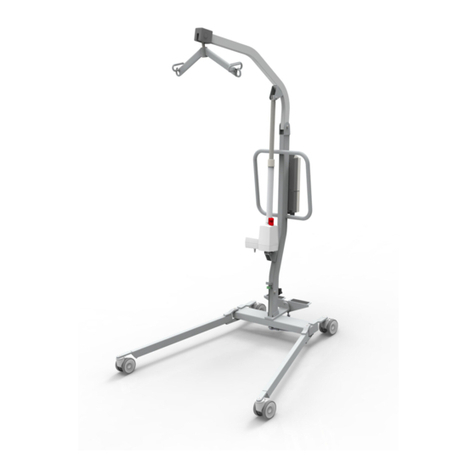
Please see below to familiarise yourself with the components of the Raiser Transfer Aid. The image below show the contents of
the Transfer Aid. If you have not received all the components contact Prism Medical UK dealer immediately – contact details are
provided on the last page of this manual.
Item
Description
1
Raiser Base
2
Raiser Handle
3
Single Knee Pad
4
Double Knee Pad
5
Brakes
6
Wheels
7
Serial Number/Product Information
Figure 1
Table 2
Figure 2
2
1
3
4
5
6
7

999061 – Revision A Page | 8 of 28
3.0 ASSEMBLY INSTRUCTIONS
3.1 Unpacking
The Transfer Aid will arrive to you in a robust box, please be careful when removing the components from the box.
Please read the user guide in full before operating.
This user manual should be kept safe for future reference.
The Transfer Aid has been specifically designed to be installed in both the professional and home health care environments.
No matter the environment, health and safety factors should be considered to ensure the safety and essential performance of
the Transfer Aid and to avoid unnecessary damage or injuries to people within the area of the Transfer Aid.
The environment in which the Transfer Aid is situated in, whilst carrying out a transfer, is required to be on a flat surface with no
steep inclines.
3.2 Unboxing Transfer Aid
When using a sharp knife, be careful not to damage the product.
This section will summarise the layout of the product packaging and what is included in the Box. It is recommended a knife is
used for smoother unpacking of the product. The product is packed into a single box (1250x600x240), weighing approximately
25kg.
Using a knife to open the box around the perimeter, the box should open to a similar view to Figure 3. It will include all the
following components. It is recommended that the components are removed in the numerical order below.
1. Base
2. Knee Pad
3. Handle
4. User Manual
Figure 3
Figure 4
3
2
1
4

999061 – Revision A Page | 9 of 28
3.3 Transfer Aid Assembly
Place the handle in the brackets as shown in (Fig. 5) below.
4.0 FREQUENLY USED FUNCTIONS
The aid may be heavy for users and will need to be lifted with care, please operate the device with the use of the
castors wherever possible to prevent any injury.
Appropriate training in the following operating procedures should be undergone by any person operating the Transfer Aid, for
their own and the client’s safety and comfort. These instructions are designed to cover the method of using the Transfer Aid.
4.1 Adjusting Knee/shin Pad (Single Knee Pad)
Adjusting the knee/shin pad height on the raiser, in the following way:
1. On the rear face of the product release the Knee/shin pad from its current location by pulling on the black locking
plungers and the same time. (see Figure 8)
2. After releasing the knee/shin pad from its current location, it is now free to move up are down to the new preferred
height for the patient. (see Figure 9)
3. Once you are happy with the new position of the pad, simply release the black locking plungers by letting go of them
both at the same time.
Step 1 - With the handle and brackets aligned, press down
until fully inserted.
Step 2 - Lock the handles to the base assembly using two M8 Star handles
and nylon shoulder washers as shown in (Fig. 6)
Caution – care required to not trap fingers
when applying the two parts together
Figure 6
Figure 8
Figure 9
Figure 10
Figure 7
Figure 5

999061 – Revision A Page | 10 of 28
4.2 Adjusting Knee/shin Pad (Double Knee Pad)
1. On the rear face of the product release the Knee/shin pad from its current location by pulling on the black locking
plungers and the same time. (see Figure 11)
2. After releasing the knee/shin pad from its current location, it is now free to move up are down to the new preferred
height for the patient. (see Figure 12)
3. Once you are happy with the new position of the pad, simply release the black locking plungers by letting go of them
both at the same time. (see figure 13)
4. To adjust the individual pads inwards and outwards, using your hand slide each pad by pushing inwards or outwards to
suit the need for the patient. (see figure 14 & 15)
4.3 Applying the brakes
To operate the Raiser Transfer Aid brakes, in the following way to activate and deactivate the brakes:
1. To activate the brakes, take your foot or hand and push down vertically on the red cycle on the brake leaver, one brake
leaver at a time. (see figure 16 & 18)
2. To deactivate the brakes, Take your foot or hand and push forward on the green dot on the brake leaver, one brake
lever at a time. (see figure 17 & 18)
Figure 18
GREEN
RED
Figure 17
Figure 16
Figure 11
Figure 12
Figure 13
Figure 14
Figure 15

999061 – Revision A Page | 11 of 28
5.0 OPERATING PRINCIPLES
This equipment should only be used by a suitably trained person. It is important that prior to using the Mackworth Raiser, a
thorough risk assessment has been carried out with the individual user and for the intended transfer. We would recommend the
use of safety belts or ladder belts for all transfers.
5.1 Standing a user who requires no assistance
1. The user’s feet should be placed on the footplate.
2. Adjust the height of the padded leg support so that the top of the pad sits just below the
user’s knee.
3. Apply the brakes to both wheels by pressing down the brake levers on both sides. These
are clearly marked with red indicating that the brakes are on and green showing that the
brakes are off.
The wheels must always have the brake applied, whilst the user is in the process of standing or sitting.
The caregiver must always counterbalance the raiser during the standing/sitting process. This can be done by placing
one foot on the back of the footplate, holding the top of the unit steady with one hand or both options together.
4. The user can now be encouraged to lean forward and take hold of the handle frame. The
caregiver should give clear instructions to the user telling them to stand whilst they are
counterbalancing the raiser.
5. Once the user is stood the caregiver may release the brakes with one foot. Pull the
Mackworth Raiser backwards and then steer it toward the new seating position.
6. Make sure that both wheels are locked again before allowing the user to sit.
The raiser is recommended for short distance transfers although a suitable risk
assessment should be carried out to determine what is considered to be a safe distance
for a user and the environment.
5.2 Standing a user who requires assistance with optional
Ladder belt.
1. The ladder belt is connected to the disc attachment on one side of the raiser. The sleeve of
the ladder belt is then placed behind the user’s bottom.
2. The caregiver can encourage/assist the user to stand themselves by pulling on the
opposite side of the ladder belt.
The user must have the ability to stand by themselves. The belt is a support aid.
3. When the user is in a standing position, the ladder belt can then be attached to the second
disc attachment.
4. Two caregivers can provide assistance when the user needs more help with standing up.
The caregiver must always counterbalance the raiser during
the standing /sitting process.
This can be done by placing one foot on the back of the
footplate, holding the top of the unit steady with one hand or
both options together.
Figure 19
Figure 20
Figure 21
Figure 22
Figure 23

999061 – Revision A Page | 12 of 28
5.3 Standing a user who requires assistance with the optional safety belt.
The Mackworth Safety Belt should be fitted to the user prior to assisting with the stand. Refer to the sling user guide.
1. Place the belt around the user’s waist, ensuring the elasticated section is placed on the user’s lumbar spine
and the solid section is place under the user’s coccyx.
2. Fasten in place using the Velcro straps and adjustable buckle fastening support belt (ensure support belt is at maximum
length)
3. The user can now be stood following same process as 5.1.
4. Once the user is stood, the buckle fastening support belt can be passed through the opening in the centre vertical
handle and adjusted to provide optimum support during the transfer
Make sure the required loop(s) are on the correct hooks and are correctly positioned
Figure 24
Figure 25

999061 – Revision A Page | 13 of 28
5.4 Compatible Belt Types
We recommend the use of the Freeway belt range (type ‘B’ applied part) to be utilised with the Mackworth Raiser. It is at the
user’s discretion to use alternative supplied product. In utilising another manufacturer’s belt, checks must first be made to
ensure the belt is safe to use and meets the requirements of BS EN ISO 10535 before its use.
The belts with a safe working load of 160kg that can be used with the Mackworth Raiser are shown below in Table 3, complete
with product codes. For all components, the lowest maximum safe working load must always be adhered to.
Size Freeway Belt Range - Product Codes
Freeway Raiser Safety Belt
XX Small 2002ACCRAISBXXS
X Small 2002ACCRAISBXS
Small 2002ACCRAISBELTS
Medium 2002ACCRAISBELTM
Large 2002ACCRAISBELTL
XL 2002ACCRAISBXL
Freeway Raiser Ladder Belt
One Size 2002ACCRAISLA
Freeway Ladder Belt
Freeway Safety Belt
Figure 26
Figure 27
Table 3

999061 – Revision A Page | 14 of 28
6.0 TECHNICAL SPECIFICATION
6.1 Raiser Dimensions – Single Knee Pad
Figure 28
Figure 29
Figure 30

999061 – Revision A Page | 15 of 28
6.2 Raiser Dimensions – Double Knee Pad
Figure 31
Figure 32
Figure 33

999061 – Revision A Page | 16 of 28
6.3 Specifications
Dimensions
Turning Circle
575mm
Overall Height
1200mm
Overall Width
592mm
Ground Clearance
21mm
Front and Rear Castors
35mm
Middle Wheel
125mm
Table 4
Weights
Safe Working Load (SWL)
160 kg
Raiser – Single Knee Pad
20 kg
Raiser – Double Knee Pad
21 kg
Handle - Single Knee Pad
8.2 kg
Handle – Double Knee Pad
9 kg
Handle
5.5 kg
Base
11.5 kg
Table 5
Operational Forces
Operating Force (with 160 kg)
100N
Operating Force (with 0 kg)
8N
Operation of the Brake
75N
Sliding the Knee Pad Up
60N
Sliding Double Knee Pad Apart
45N
Table 6
Expected Product Lifetime
10 yrs. depending usage and compliance to maintenance, servicing and LOLER inspections.
6.4 Standards Applied
The standards that have been applied to the device are as follows:
•EN 12182:2012 Assistive products for persons with disability – General requirements and test methods

999061 – Revision A Page | 17 of 28
7.0 ENVIRONMENTAL - STORAGE AND OPERATING
CONDITIONS
The Transfer Aid is intended for internal use within normal environmental conditions.
It is not intended to be used in environments where there are rapid changes in the environmental temperature and
humidity during intended use.
7.1 Normal Operating Conditions
+5°C to +40°C (41°F to 104°F) at a relative humidity between 15% to 90% RH, non-condensing but not requiring a water vapour
pressure greater than 50hPa and atmospheric pressure between 700hPa to 1060hPa.
7.2 Shipping and Storage Conditions
-25°C to +5°C (-13ºF to 41ºF) with any humidity level.
+5°C to +35°C (41°F to 95°F) at a relative humidity up to 90%.
+35°C to 70°C non-condensing at a water vapour pressure up to 50hPa.
8.0 DISPOSAL
When the Transfer Aid has completed its life cycle and can no longer perform to its intended use safely the Aid
must be decommissioned by an approved Service Engineer. The following specifies the importance of correct
disposal procedure including local laws and being environmentally friendly.
Please observe the local laws on recycling and respect the current laws for disposal within the community the
device is being used within. If there is any uncertainty of the below guidelines, contact your local authorities to
determine the proper method of disposal of potentially biohazardous parts and accessories.
The relevant components utilised in the manufacture of the device that can be recycled at the end of the
device life are:
Fully recyclables:
Consideration when Recycling:
Steel frame (Handle, Base)
Knee Pad
Castors
Initial packaging of the device (cardboard)
Metallic fixing – screws etc.
The product may be contaminated and has to be disinfected before recycling or disposal.
See section 10.3 ‘Cleaning’ for details of how to do this.
Table 7

999061 – Revision A Page | 18 of 28
9.0 FAULT FINDING
Should a problem arise with the use of the Transfer Aid, review the Table below.
Find the fault and complete the recommended solution.
If the fault is not found and/or the solution does not correct the problem, contact your local Prism Medical UK authorized dealer
immediately – contact details are provided on the last page of this manual.
Fault
Action
Castors do not operate.
Ensure the brake has been fully disengaged, Check the castors are free running
Check the castors are touching the ground. If this does not correct the fault, then
contact your local authorised dealer immediately so the Transfer Aid can be
checked to ensure proper continued operation.
Knee Pad does not lock into position
Ensure that the index plunger is aligned with the holes in the handle. If this does
not correct the fault, then contact your local authorised dealer immediately so
the Transfer Aid can be checked to ensure proper continued operation.
Handle is loose
Ensure that the star nuts are fully tightened (Refer to section 4.0) If this does not
correct the fault, then contact your local authorised dealer immediately so the
Transfer Aid can be checked to ensure proper continued operation.
Brakes do not operate
Ensure that the brake mechanism is fully engaged, check to see if both wheels
are touching the ground. If this does not correct the fault, then contact your
local authorised dealer immediately so the Transfer Aid can be checked to
ensure proper continued operation.
Table 8
10.0 GENERAL INSPECTION, MAINTANANCE AND
CLEANING
10.1 Service
No service is to be carried out on the Raiser Transfer Aid while transferring a person to reduce the risk of injury.
Service must be completed by a Prism Medical UK authorised Service Engineer.
Do not attempt to service the product yourself, or warranty is void.
To ensure the safety and continued good function of your Transfer Aid, routine service must be performed on your Raiser
Transfer Aid.
Service should be completed by a Prism Medical UK approved service engineer every 6 months to ensure the products required
standard is maintained. The service history of the product should be documented each service in the Service Log at the back of
this User Manual.
When the Transfer Aid is serviced, the 6 month service checklist must be completed for the Raiser Transfer Aid.
Service Manual Document Number: 995061.
Spare Parts Manual Document Number 992061
The Service must be completed every 6 months after installation of the Transfer Aid to comply with LOLER Regulations.
The Raiser Transfer Aid has an expected Service Life of 10 Years.
Contact your local authorised Prism Medical UK dealer if you:
•Need more information.
•Have any questions about the use or service of your Transfer Aid.
•Notice any change in the performance.
•Want to report an unexpected occurrence.
•Want to arrange a service.
•Need to ascertain necessary information for replacement parts and components.
Contact details of your local Harvest Healthcare dealer are shown on the last page of this manual.

999061 – Revision A Page | 19 of 28
10.2 Inspection
Inspection is to be completed prior to each use by the user of the Transfer Aid.
Should any of the components in the table below fail the inspection, DO NOT use the Transfer Aid.
Contact your local authorised dealer for service – contact details are on the last page of this manual.
Ensure all component inspections in the Table below are completed prior to each use of the Transfer Aid.
Check List before Use
Component
Service/Inspection required
Generic:
Visual inspection of the external of the Transfer Aid. Significant damage that may
affect the function of the Transfer Aid along with a clear safety hazard is
unacceptable.
Check the Labelling on the Transfer Aid to ensure they are all still legible, this
includes the Serial Number and other important markings. If labels are not legible,
then contact your local authorised dealer immediately.
Check all main nuts and bolts to see if they are loose, if found that they are then
contact your local authorised dealer immediately.
Examine the sling hooks on the handle bar for excessive wear and sharp edges.
Handle Assembly:
Ensure that the Installation of the handle to base is correct and fitted properly, as
well as the fixing bolt and star handle have been installed. If necessary, tighten the
star handle if loose.
Knee Pad:
Inspect the Knee Pad for damage including cuts and breaks.
Ensure height adjustment to the Knee Pad is moving freely and is not jamming.
Ensure all height adjustment positions are locking correctly
Brakes:
Ensure the Brakes function when activated
Ensure the Transfer Aid can move freely when the Brakes are deactivated. (Ensure
they aren’t rubbing on the Wheels)
Castors and Wheels
Examine the products Wheels and Castors for signs of damage or wear, ensure
they run freely and are not cracked.
Check to see all castors are flat on the floor and Transfer Aid is stable.
Ensure the product is able to rotate freely with ease.
Base:
Ensure the Foot Grips are still applied and undamaged.
Belts :
Examine belts for fraying or other damage. DO NOT use belts with fraying or
damage to the suspension straps or tears in the body of the sling.
Table 9

999061 – Revision A Page | 20 of 28
10.3 Cleaning
Please follow the cleaning guidelines below on cleaning and disinfecting the Transfer Aid.
10.3.1 General cleaning
It is recommended to clean the Raiser and accessories before the use by a different patient, reducing the risk of
cross–contamination.
The exterior of the Raiser can be cleaned using a damp soapy cloth for general cleaning duties. Please ensure the
cloth is damp and not wet. Ensure the exterior of the device is dry after cleaning. Dry using a clean dry cloth.
10.3.2 Disinfecting (if necessary)
Should the Transfer Aid require a more thorough clean, the use of the Actichlor™ disinfectant product (which is widely available
in tablet form and used throughout the health care industry) is recommended.
Follow the manufacturer’s safety instructions for the use of the cleaning product before use to ensure safe use for
the operator and the patient.
Ensure the cloth is damp before the cleaning process.
Application is through a clean damp cloth applied to wipe the device down. Use in the following dilutions to ensure an effective
clean:
•Actichlor™ dissolvable chlorine tablets provide a concentration of 1000 ppm of available chlorine (0.1%) per 1 tablet
•1 tablet (1.7g formed tablet (x1)) will create a virucidal solution, diluted in 1 litre of water to provide effective means to
clean a “dirty” device. This is also ideal for use after an outbreak of the Norovirus/winter vomiting and can be used as a
precaution against C.Diff. It is effective against viruses, bacteria, spores, yeasts and moulds.
•The contact time against the outer components of the device should be for 5 minutes to prevent any virucidal
infections without a degradation to the functionality of the device. 5 minutes is a recommended contact time. The
device can withstand a longer contact period but the 5 minute recommendation as a minimum must be followed to
provide an effective cleaning regime.
•Blood spills should be dealt with by an increased concentration of the solution – please refer to the instructions on the
manufacturers product labelling.
Dilution chart
Product used as
Device condition
Concentration
(ppm)
Dilution qty* (l)
Tablets per
1l (0.26gal)
Contact
time
(minutes)
Bactericidal
Clean
200
5 (1.32gal)
1
1
Dirty
1000
1 (0.26gal)
1
5
Yeasticidal
Clean
200
5 (1.32gal)
1
1
Dirty
1000
1 (0.26gal)
1
5
Fungicidal
Clean
2000
1 (0.26gal)
2
15
Dirty
5000
1 (0.26gal)
5
15
Mycrobactericidal
Clean
1000
1 (0.26gal)
1
15
Dirty
5000
1 (0.26gal)
5
15
Virucidal
Clean
500
2 (0.53gal)
1
5
Dirty
1000
1 (0.26gal)
1
5
Sporcidal (C.Diff)
Clean
1000
1 (0.26gal)
1
10
-
-
-
-
-
Sporcidal
Clean
5000
1 (0.26gal)
5
10
-
-
-
-
-
* Dilution is made with water. DO NOT dilute within any other medium.
•When diluted in water, one tablet gives 1000ppm of available chlorine.
•The concentration of the solution depends upon whether the object being cleaned is noticeably dirty (indicated
in the table by “Device condition”.
Table 10
Table of contents
Other Mackworth Medical Equipment manuals

Mackworth
Mackworth 180 Mobile Hoist User manual

Mackworth
Mackworth HOLLY User manual

Mackworth
Mackworth Hazel Classic Universal User manual

Mackworth
Mackworth M180 User manual

Mackworth
Mackworth TX440 Advanced PT User manual

Mackworth
Mackworth FSG Quick start guide

Mackworth
Mackworth M Series User manual

Mackworth
Mackworth SA180E User manual

Mackworth
Mackworth SA400 User manual

Mackworth
Mackworth M180 User manual