manuals.online logo
Brands
  1. Home
  2. •
  3. Brands
  4. •
  5. Macnaught
  6. •
  7. Tools
  8. •
  9. Macnaught HG 20F-012KMM-01 User manual

Macnaught HG 20F-012KMM-01 User manual

HG20F-012KMM_inst_ Issue 1 © 2023 1
HG 20F-012KMM-01
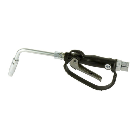
OIL CONTROL GUN
GENERAL INFORMATION
IMPORTANT INFORMATION
Your safety is important to us. Please read and follow
all safety instructions listed inside.
“Cautions” listed throughout this manual advise of
potential practices or procedures which may cause
damage to your equipment.
Ensure all operators have access to the instructions
about safe operating and maintenance procedures.
Do not exceed the maximum working pressure of 6900
kPa / 1000 psi / 69 bar.
Do not hit the oil control gun if it fails to operate. Refer
to “trouble shooting guide” or return the unit to your
nearest authorised service centre.
Never point the nozzle at yourself or anyone else.
Never exceed the pressure rating of any component
installed in the System.
This manual assists you in operating and maintaining your
new oil control gun. The information contained will help
you ensure many years of dependable performance and
trouble free operation.
INSTRUCTION MANUAL
INTRODUCTION
Please read and retain this instruction manual to
assist you in the operation and maintenance of this
quality product.
Thank you for purchasing a Macnaught oil dispensing
gun. The Macnaught metered oil dispensing gun has
been designed for use with engine and gearbox oils up
to SAE140.
READ THIS INFORMATION CAREFULLY
CAREFULLY BEFORE USE.
CAUTION
If you require further assistance please contact your local
Macnaught distributor or authorised Macnaught service
centre.
* Macnaught recommends the use of PPE equipment
such as safety glasses, protective gloves, safety
shoes etc before handling or using this product.
* Continual use of this product can potentially cause
RSI injury (especially hand or arm injury)
* Do not modify or alter this product any way
* Only physically fit people should be authorised to
use this product
* Ensure that any fluid spillage is cleaned up
immediately to prevent slipping or injury.
HG20F-012KMM_inst_ Issue 1 © 2023 2
Before every use check all hoses for signs of wear,
leaks or loose fittings. Tighten all fluid connections
regularly and replace weak or damaged hoses.
ASSEMBLY
Use Teflon tape (or suitable thread sealant ) when
connecting the oil control gun to an oil hose.
OUTLET NOZZLE OPERATION
When fluid flows through the gun the outlet nozzle will
automatically open. When the fluid flow stops the outlet
nozzle will automatically shut.
HANDLE OPERATION
To latch the handle, squeeze the lever, push the button
and then release lever.
To release the latch in manual mode simply squeeze and
release lever.
CONTROL HANDLE DISASSEMBLY
Use a clean bench to carry out maintenance.
A) Remove the oil hose from the control gun inlet swivel
(10).
B) Unscrew and remove swivel (10) washer and o’ring
from the control gun inlet. (Clean or replace the swivel
strainer and o’ring if required).
The swivel is under spring tension
C) Remove valve spring (9), seal/valve body assembly (8).
and plunger (7).
D) Remove the screw (15), then unclip and remove the
trigger guard (16).
LEVER and VALVE REMOVAL
A) Using a 2.5mm allen key, remove the 2 handle screws
(2).
B) Remove lever (11), ease downwards.
C) Remove the washer (5), “O”Ring (3), then push the
valve cam (4) from the gun body (6), and remove “O”Ring
(3).
Note: If the plunger has not been removed the cam will not
release from the body.
CONTROL HANDLE REASSEMBLY
A) Clean and inspect all parts. Replace any suspect,
worn or damaged components.
Note: Lightly lubricate the valve cam before assembly.
B) Place “O”Ring (3) onto valve cam (4).
Note: The cut out section in the middle of the valve cam
(4) must face the inlet swivel (10).
C) Replace the valve cam (4) into the body (6). Note the
orientation shown on the assembly drawing. Fit the
second “O”Ring (3) and washer (5).
D) Slide lever assembly (11) into position and replace the
two Allen screws (2). (Use Loctite or similar sealant).
E) Replace plunger (7).
Note: The end hole in the plunger must face the gun
outlet.
F) Replace the seal/valve body assembly (8), and
spring (9) and replace into the gun body (6).
Note: Install the spring, small end first.
G) Re-fit the trigger guard (16) and replace screws (15)
H) Replace washer, o’ring on to the swivel assembly (10),
and screw firmly into place (Use Loctite or similar
sealant).
Note: After assembly ensure the handle latch is operating
correctly.
Before carrying out any maintenance disconnect the
air supply to the pump and release the fluid pressure
in the system by pressing the lever on the control gun.
CAUTION
CAUTION
IM012KMM METER INSTRUCTIONS
RESET BUTTON
The RESET button allows you to reset the Reset Total to
zero.
Ensure the fluid supply to the meter is disconnected
and the line pressure is released before disassembly.
CAUTION
Never exceed the pressure rating of any component
installed in the System.
DISSASSEMBLY and REASSEMBLY
The IM012KMM flow meter can be easily disassembled
without having to separate the body from the installation.
MEASURING CHAMBER
To access the measuring chamber:
A) Remove the rubber shroud
B) Unscrew the 6 screws located under the meter
body
C) Remove the lid
D) Remove the gasket and oval disk
E) Remove the gears
Note: Reassembly is the reversal of disassembly
taking particular care to:
1) Check gasket seals for damage and replace if
required.
2) Lubricate and carefully install the gasket seal
3) Replace and tighten screws correctly
4) Hold the meter with the inlet facing down, and place
the outlet gear on the right hand side of the meter.
5) Check that the gears are turning correctly
6) Fit the lid to the top of the chamber ensure that the
gears on lid correspond with that on the chamber
outlet.
HG20F-012KMM_inst_ Issue 1 © 2023 3
PARTS DIAGRAM
SPARE PARTS LIST
HG20F-012KMM
ORDER FOR REPLACEMENT
ITEM NO OFF PART/SET No KIT. REF DESCRIPTION
HG20-1K (Kit A) Seal Kit
1 1 IM078As Flexible Extension with Auto Nozzle
2 2 A Screw (M4 x 8 CSK)
32 AO-ringBS111
4 1 A Camshaft
5 1 A Washer
6 1 n/a - order HG20 (gun body complete) Body Casting
7 1 A Plunger Cage
81 AValveSeal
91 ASpring
10 1 HG040As (BSP) Swivel Assembly (BSP)
10 1 HG043As (NPT) Swivel Assembly (NPT)
11 1 Handle (Latching)
12 1 HG022s incl item 2 A Lever Plug
13 1 A Push Button - Auto
14 1 A Button Spring
15 2 A Screw
16 1 Handle guard
17 1 Adaptor
18 2 Lock nut
19 2 O-ring
1
Replacement meter order - IM012KMM-01
HG20F-012KMM_inst_ Issue 1 © 2023 4
TROUBLE SHOOTING GUIDE
PRODUCT SPECIFICATIONS:
For Warranty Terms and Conditions see macnaught.com.au
For a list of Australian Service Centres see macnaught.com.au
* When tested with lubrication oil @ 25°C. Allowances should be made for changes to these parameters.
* Accuracy +/- 1%
Batch Total 999.9
Accumulative Total 999999.9
Wetted components: Acetal, aluminium, nitrile (NBR), mild steel
Flow Range: 1-30 litres/minute (0.26-8 US gal/min)
Max. working pressure: 6900 kPa / 1000 psi / 69 Bar
Inlet thread - Gun ½” BSPT
Outlet thread: -Meter ½” BSPP
Operating temperature: -10°C (14°F) to +55°C (131°F)
Weight (approx): 1.75kg
Note:
This product should be disposed of according to all applicable local
and national government environment regulations and guidelines.
TROUBLE CAUSE REMEDY
Inaccurate a) Measuring chamber dirty or clogged a) Clean measuring chamber (ref disassembly and
reassembly section)
b) Air in system b) Eliminate any leaks and purge air from the system
Low flowrate a) Measuring chamber is dirty or clogged a) Clean measuring chamber (ref disassembly and
reassembly section)
b) Measuring chamber is dirty or clogged b) Clean measuring chamber (ref disassembly and
reassembly section)
c) Damaged plunger seal c) Replace damaged plunger seal
Constant oil leak from the nozzle a) Damaged plunger seal a) Replace plunger seal ( check for damage )
Intermittent drip from the nozzle b) Dirt in the nozzle b) Remove the nozzle and blow out any dirt particles,
replace if necessary.
Oil leak from the lever assembly area a) Damaged o’rings a) Replace damaged o’rings
Oil leaking from the swivel inlet a) Damaged o’ring or swivel a) Replace swivel

Other Macnaught Tools manuals

Macnaught K7/KR MINI-LUBE Series User manual

Macnaught

Macnaught K7/KR MINI-LUBE Series User manual

Macnaught BG100 User manual

Macnaught

Macnaught BG100 User manual

Macnaught M3D-SSAW3850-H User manual

Macnaught

Macnaught M3D-SSAW3850-H User manual

Macnaught MINI-LUBE K6 User manual

Macnaught

Macnaught MINI-LUBE K6 User manual

Macnaught Retracta R3 User manual

Macnaught

Macnaught Retracta R3 User manual

Macnaught LEVERGUN K40-01 User manual

Macnaught

Macnaught LEVERGUN K40-01 User manual

Macnaught powergun pg450 User manual

Macnaught

Macnaught powergun pg450 User manual

Macnaught B2-01 User manual

Macnaught

Macnaught B2-01 User manual

Macnaught K57-01 User manual

Macnaught

Macnaught K57-01 User manual

Macnaught Retracta F Series User manual

Macnaught

Macnaught Retracta F Series User manual

Macnaught Flexigun K29 User manual

Macnaught

Macnaught Flexigun K29 User manual

Macnaught M3D-DEF-7530 User manual

Macnaught

Macnaught M3D-DEF-7530 User manual

Macnaught RETRACTA FHM1900-01 User manual

Macnaught

Macnaught RETRACTA FHM1900-01 User manual

Macnaught M3D-SSAW-5050 User manual

Macnaught

Macnaught M3D-SSAW-5050 User manual

Macnaught K29-01 User manual

Macnaught

Macnaught K29-01 User manual

Macnaught RETRACTA C1 User manual

Macnaught

Macnaught RETRACTA C1 User manual

Macnaught lubemate L-OD90B User manual

Macnaught

Macnaught lubemate L-OD90B User manual

Macnaught MATP1220 User manual

Macnaught

Macnaught MATP1220 User manual

Macnaught K53-01 User manual

Macnaught

Macnaught K53-01 User manual

Macnaught MAN1915-01 User manual

Macnaught

Macnaught MAN1915-01 User manual

Macnaught Lubermate L-AWP1015 User manual

Macnaught

Macnaught Lubermate L-AWP1015 User manual

Macnaught HG20R-01 User manual

Macnaught

Macnaught HG20R-01 User manual

Macnaught KR PRESSURITE User manual

Macnaught

Macnaught KR PRESSURITE User manual

Macnaught OKTR585-1-001 User manual

Macnaught

Macnaught OKTR585-1-001 User manual

Popular Tools manuals by other brands

Grant's 57317 Owner's manual & safety instructions

Grant's

Grant's 57317 Owner's manual & safety instructions

Herth+Buss 95942299 Operating	 instruction

Herth+Buss

Herth+Buss 95942299 Operating instruction

Pig SpillBlocker quick guide

Pig

Pig SpillBlocker quick guide

Air Vise and Workholding AirVice manual

Air Vise and Workholding

Air Vise and Workholding AirVice manual

BGS technic 9754 manual

BGS technic

BGS technic 9754 manual

Ryobi A25RT02 Operator's manual

Ryobi

Ryobi A25RT02 Operator's manual

Eastwood Elite 64646 Assembly and operating instructions

Eastwood

Eastwood Elite 64646 Assembly and operating instructions

Lifetime TRIPLE THREAT instruction manual

Lifetime

Lifetime TRIPLE THREAT instruction manual

Lobtex ARV-022M Operation manual

Lobtex

Lobtex ARV-022M Operation manual

Nakanishi RA-200 Operation manual

Nakanishi

Nakanishi RA-200 Operation manual

Zolix Instruments PSA Series operating manual

Zolix Instruments

Zolix Instruments PSA Series operating manual

Huskie Tools ECO-MK7EZ Operator's manual

Huskie Tools

Huskie Tools ECO-MK7EZ Operator's manual

Atlas Copco SMC-TT-10-850 instructions

Atlas Copco

Atlas Copco SMC-TT-10-850 instructions

Metabo SMG ISO Series Operation manual

Metabo

Metabo SMG ISO Series Operation manual

tormek DBS-22 Instruction

tormek

tormek DBS-22 Instruction

NEO TOOLS 08-821 manual

NEO TOOLS

NEO TOOLS 08-821 manual

M7 DS-201 instruction manual

M7

M7 DS-201 instruction manual

norbar PTM-IC Series Quick reference guide

norbar

norbar PTM-IC Series Quick reference guide

manuals.online logo
manuals.online logoBrands
  • About & Mission
  • Contact us
  • Privacy Policy
  • Terms and Conditions

Copyright 2025 Manuals.Online. All Rights Reserved.