Compact current relay and
protection assemblies RXHL 401 and
RAHL 401
1MRK 509 062-BEN
Page 2
Functions Overcurrent
protection
Application
In radially fed power networks the phase
overcurrent function can be used as main or
back-up short circuit protection for lines and
transformers. The time current characteristic
(definite time or any of the inverse time char-
acteristics) should be chosen according to
common practice in the network. Normally
the same time current characteristic i used for
all phase overcurrent relays in the network.
This includes phase overcurrent protection
for lines, transformers and other equipment.
The measuring relay offers great flexibility in
the choice of time characteristic.
There is a possibility to use phase overcurrent
protection in meshed systems as short circuit
protection for lines. It must however be rea-
lised that the setting of a short circuit protec-
tion system in meshed networks, can be very
complicated and a large number of fault cur-
rent calculations are required. There are situa-
tions where there is no possibility to achieve
selectivity with a protection system based on
phase overcurrent relays in a meshed system.
In combination with impedance relays or line
differential protections, phase overcurrent
relays can serve as back-up short circuit pro-
tection for parts of the lines.
For shunt capacitors, shunt reactors, motors
and other similar equipment phase overcur-
rent protection can serve as main or back-up
short circuit protection. Also for these appli-
cations the time characteristics should be cho-
sen so that co-ordination with other
overcurrent protection in the power system
can be made.
As the short circuit current level will change
depending on the switching state in the power
system, there is a great benefit to be able to
change parameter-setting groups when the
switching state in the system is changed. The
measuring relay will enable this.
The blocking option can be used to decrease
fault time for some fault points (for example
busbars) in radially fed networks.
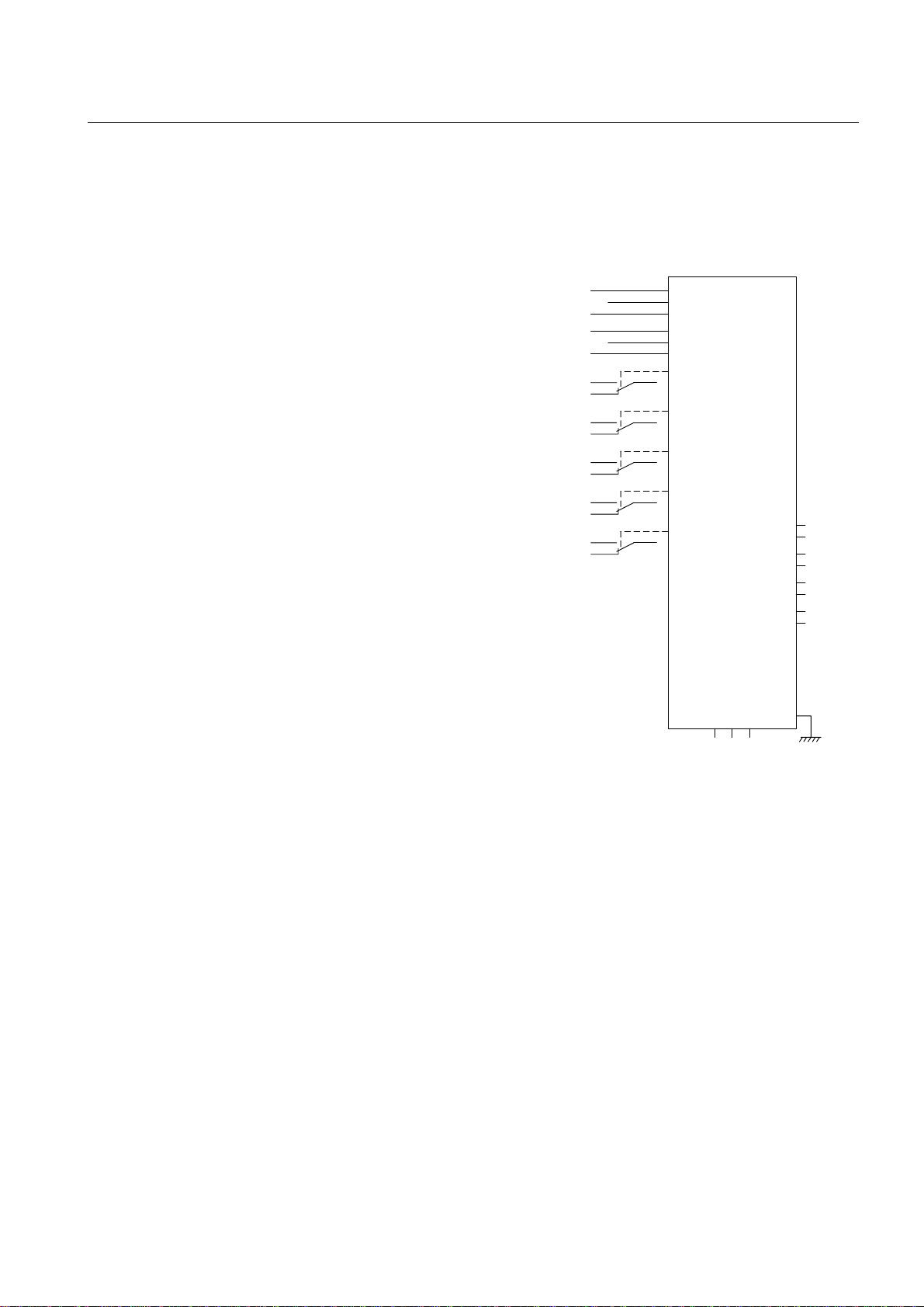
Design
The overcurrent protection has a low set stage
with inverse or definite time delayed func-
tion. The inverse time characteristics are pro-
vided with minimum operate time for
improved selectivity in certain applications.
The low set stage also has a reset time logic
for detection of intermittent faults. If the pro-
tection starts and the fault current drops the
reset of the function will be made gradually
so that the integrated fault current time area
will be remembered for some time. In case of
an intermittent fault every re-strike of the
fault will increase the integrated current-time
area so that the fault can be tripped.
The overcurrent protection has two high set
stages with definite time delayed function.
The overcurrent protection is designed for
low transient overreach which allows
extended reach and smaller setting margins.
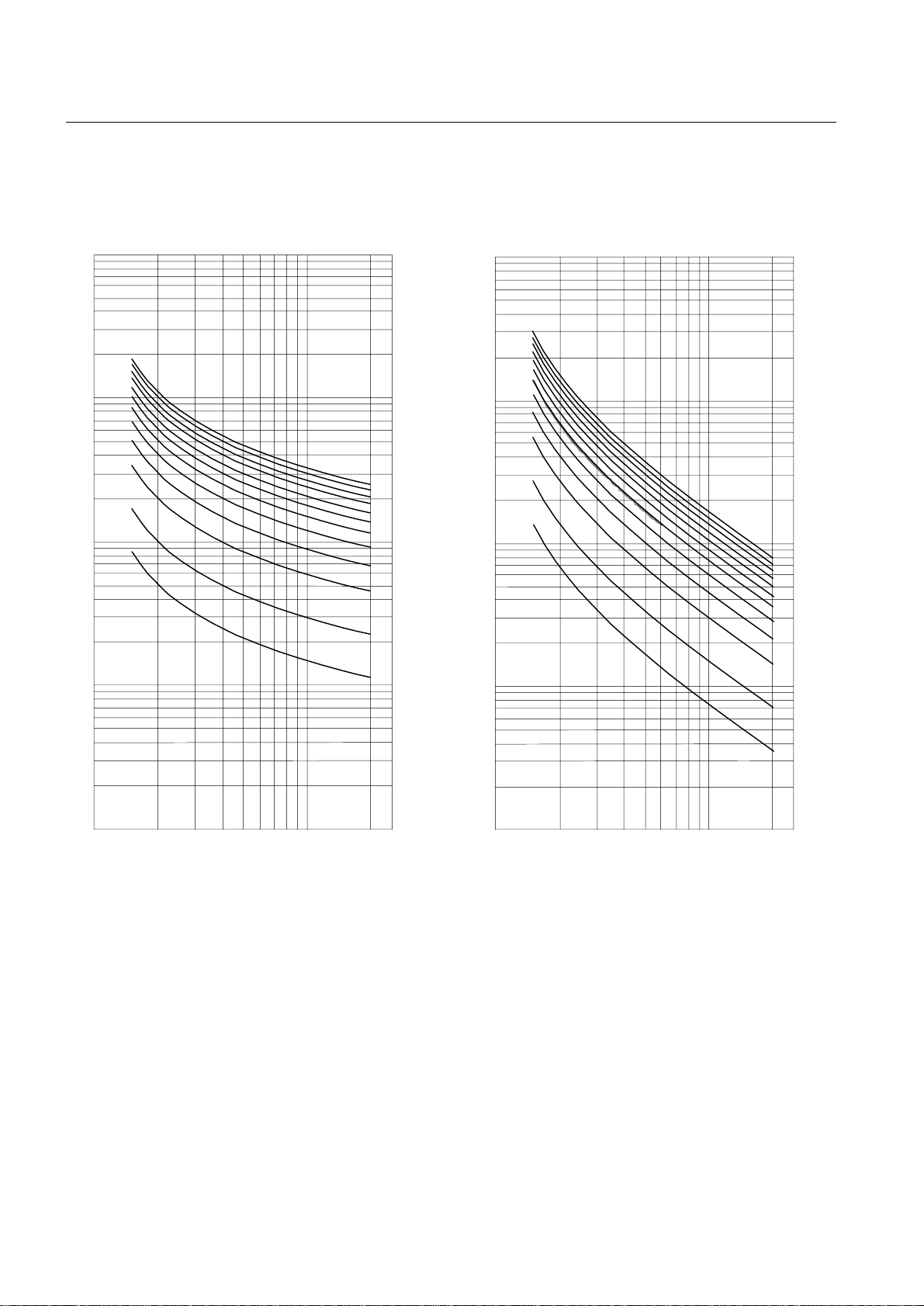
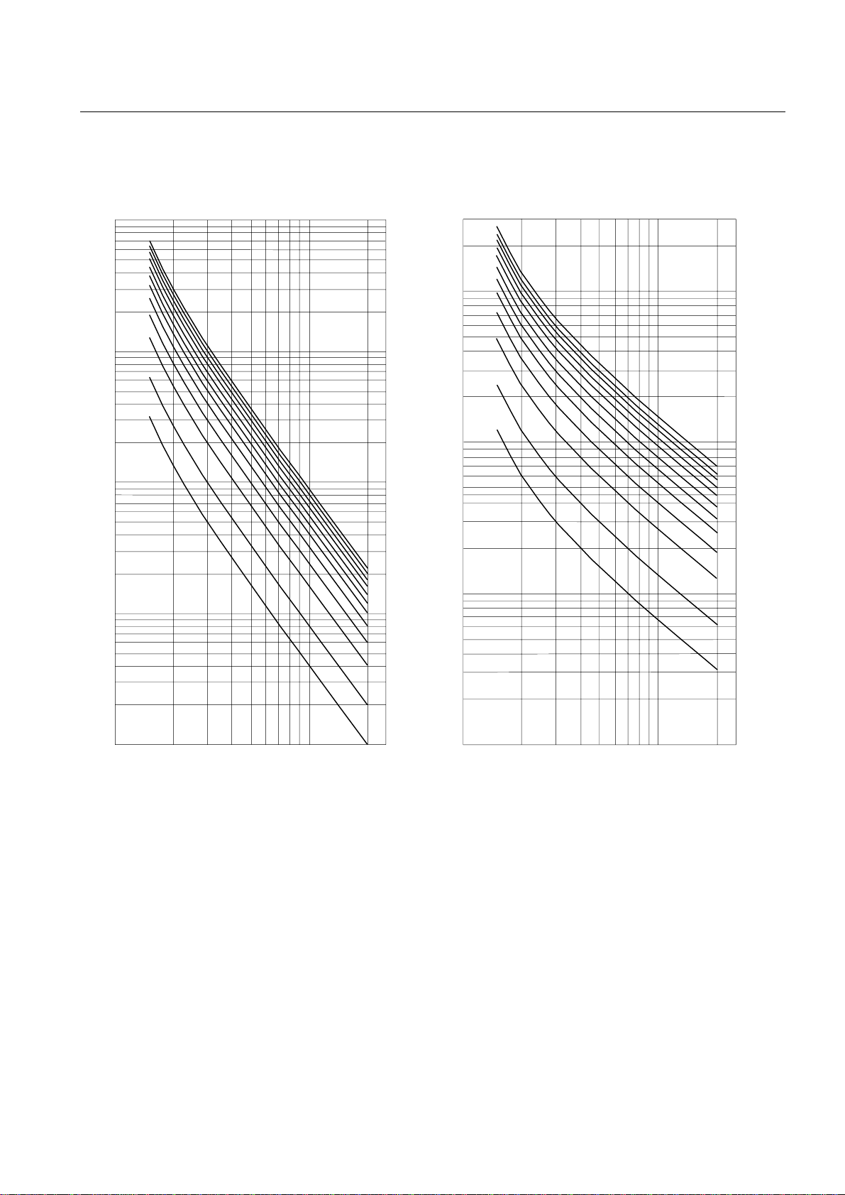
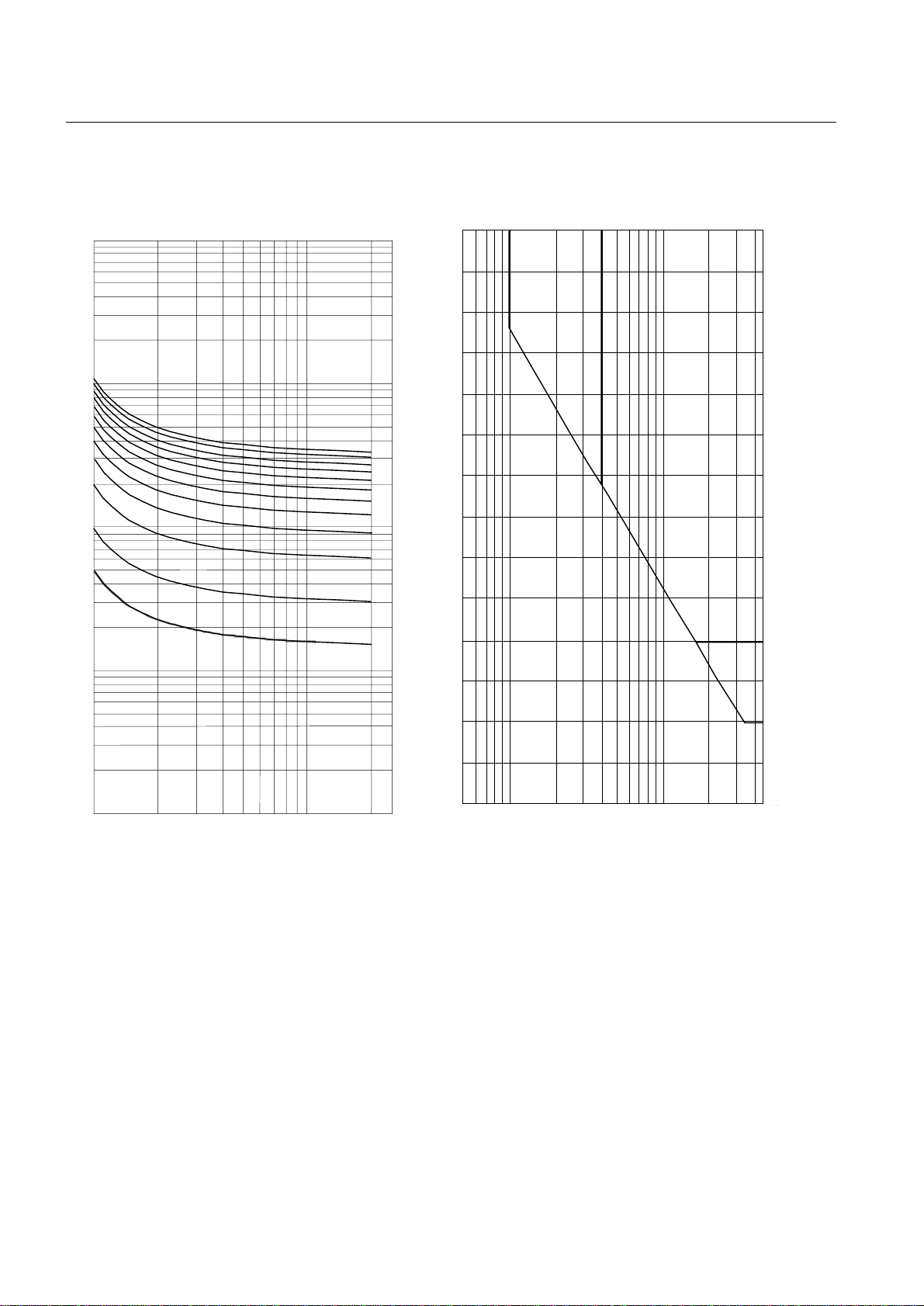
The following characteristics are selectable
for the low set stage (diagrams are shown in
the chapter “Design description”):
1 Definite time delayed
2 Inverse time delayed:
- Normal inverse (NI)
- Very inverse (VI)
- Extremely inverse (EI)
- Long time inverse (LI)
- RI inverse (RI)
NI, VI, EI and LI according to IEC 60255-3.
RI-curve according to old electromechanical
relays manufactured by ASEA.
Earth-fault protection
Application
The earth-fault protection is non-directional
and based on a measurement of the residual
current. It is mainly used in solidly and low
impedance grounded networks. In high
impedance grounded networks, the size of the
network and nationalstandards are the factors
determining whether the protection can be
used. The high set stages are used in the simi-
lar way as they are in the phase overcurrent
protection, but only in solidly and low imped-
ance grounded networks.
In solidly grounded networks the earth-fault
currents can be of the same order of magni-
tude as the short-circuit currents.
Earth-faults with high fault resistance can be
detected by measuring the residual current.
This type of protection provides maximum
sensitivity to high resistive earth-faults. It is