manuals.online logo
Brands
  1. Home
  2. •
  3. Brands
  4. •
  5. Siemens
  6. •
  7. Relay
  8. •
  9. Siemens 7UG0583-1CU20 User manual

Siemens 7UG0583-1CU20 User manual

1
s
Operating Instructions
Speed Monitoring Relay
7UG0583-1CU20
7UG0
IEC 60947-5-1
Please read and understand these instructions before installing,
operating, or maintaining the equipment.
DANGER
Hazardous voltage can cause death or serious injury.
Disconnect power before working on equipment.
CAUTION
Reliable functioning of the equipment is only ensured
with certied components.
Overvoltage category II
(Refer IEC 60947-1)
NOTICE
This product has been designed for environment A. Use of this product
in environment B may cause unwanted electromagnetic disturbances in
which case the user may require to take adequate mitigation measures.
Technical Data
Designation 7UG0583-1CU20
Type Speed monitoring relays
Control voltage (Uc) 110 - 240V AC/DC
Tolerance on Control supply 0.85x Uc… 1.1x Uc
Frequency 50/60Hz
Operating temperature 0 to 50°C , 95%RH (non-condensing)
Sensor Supply 12VDC, 30mA (±10%)
(Short circuit protected)
Count inputs 5 to 30VDC from proximity
switches, encoders, solid state devices
or potential free contacts
Trip Time delay 0 to 99.9 sec (programmable)
Rate Range Auto ranging resolution
User selectable : RPS / RPM / RPH
Operating modes Under speed, Over speed and Dual
speed
Scale factor Programmable from 0.001 to 9.999 x
10nwhere n = -3, -2, -1, 0, 1, 2.
Measurement range 4 - 9999 RPM
Rated output relay current 5A (AC12)
Relative metering precision ±15 %
Accuracy of digital display ±1 RPM
Pulse duration minimum 3 ms
Pulse interval minimum 3 ms
Max. Power consumption 3.2 VA
Terminal connections
Encoder
+12V CNT GND
-
WIRING DIAGRAM FORCOUNT INPUT
NPN
COM
Potential free contacts (NPN)
+12V CNT GND COMNPN
-
+12V CNT GND
-
COMNPN
Potential free contacts (PNP)
*
**
2
7UG0583 - 1CU20
0.5 Nm
5
Solid
1 x (0.75 to 2.5) mm2
2 x 0.5 to 2 x 1.5 mm2
5
Stranded with end sleeve
1 x (0.5 to 2.5) mm2
2 x (0.5 to 1.5) mm2
Front panel key functions
From Page 1.
* By default, Sensor type will be considered as PNP.
In case of NPN sensor type, NPN-COM to be shorted.
** For three wire sensor, connect the sensor to internal +12V as shown
or use external supply (5 to 30V) if required.
Note: If the sensors require more than 30mA current, use external power
supply to power the sensors. To reduce noise, Use of Snubber across load
is recommended.
Note:
1. In Configuration mode,
Both the relays will turn OFF.
2. Set-Point High will only accept values greater than Set-Point Low. Also, both values should be Integer.
3
CONFIGURATION SCHEME (Parametersetting)
Pressthe OK ()keyfor3seconds to enter/ exit the configuration settings. Both therelays will turn OFF.
Configuration.
Parameter
Display
Description
Initial Time
Delay
To go to next page before3seconds is complete
Key:
Blinking for3seconds
*
Key:Increments the blinking digit afterevery key. press
and rolls over from 0to9
Key: Shiftthe blinking to next digit (right) forevery keypress
Trip Time
Delay
To go to next page before3seconds is complete
Key:
Blinking for3seconds
*
Key:Increments the blinking digit afterevery key. press
and rolls over from 0to9
Key: Shiftthe blinking to next digit (right) forevery keypress
RelayReset
Mode
To go to next page before3seconds is complete
Key:
Blinking for3seconds
*
Key:Changes relayreset mode
Range: Default:Auto, Manual Auto
To go to next page before3seconds is complete
Key:
Blinking for3seconds
*
To go to next page before3seconds is complete
Key:
*
Key:Changes mode of operating
Dual, Under,OverRange:
Blinking for3seconds
*
To go to next page before3seconds is complete
Key:
*
Key:Changes factor of rate
RPM, RPS, RPH RPMRange: Default:
Rate Mode
Blinking for3seconds
*
Operating
Mode
To go to next page before3seconds is complete
Key:
Key : Increments the blinking digit after every key press
n = -3, -2, -1, 0, 1, 2
*
Factory
reset
To go to next page before3seconds is complete
Key:
Blinking for3seconds
Key:Increments value (0-5). No action from 0-4. Factoryreset
when ENT is pressed at 5.
Exponent
Blinking for3seconds
*
Scale Factor
Mantissa
User Guide
Modes of Operation:
i) Under-speed Mode: The relay checks whether the speed of the
monitored system is lower than a particular set-point, dened as Set-
point Low. R2 is energized when the frequency of rotation becomes
lower than Set-Point Low.
ii) Over-Speed Mode: The relay checks whether the speed of the
monitored system is greater than a particular set-point, dened as Set-
Point High. R1 is energized when the frequency of rotation becomes
greater than Set-Point High
iii) Dual-speed Mode: The relay checks whether the speed of the
monitored system is within a particular range, dened as Set-Point
Low to Set-Point High. R2 is energized when the frequency of rotation
becomes lower than Set-point Low. R1 is energized when the frequency
of rotation becomes greater than Set-point High.
Note: Relay 1 has been assigned for Over-speed and Relay 2 has been
assigned for Under-speed by default. These cannot be interchanged.
Both the relays are NOT energized when the connected motor is operating
within the preset range.
Scale Factor:
The user programmable scale factor facilitates the direct reading in
desired engineering unit. The counter multiplies the number of pulses
received at the count input with the scale factor, and displays the result.
Rate display = Number of pulses received per minute x scale factor or No.
of pulses received per hour x scale factor.
The scale factor consists of two parts, mantissa and exponent. The
mantissa can be set from 0.001 to 9.999 and the exponent can be set
from -3 to +2.
The scale factor is arrived at as:
Scale factor = Mantissa X 10Exponent
Scale Factor cannot be 0 for obvious reasons.
Initial Time Delay (ITD): It is the time required by the motor to gain opti-
mum speed. When the ITD is entered and unit is powered ON, the unit
waits for the ITD to elapse (in addition to TTD) before switching the relay
outputs in case of any unhealthy condition.
Trip Time Delay (TTD): Sometimes the motor speed can go out of range
for a while. In order to avoid the relay tripping due to such momentary
changes in frequency, Trip time delay is provided. The relay trips only if
unhealthy speed ensues after TTD has elapsed.
Relay reset modes: This feature allows one to customize the operating of
both the relay outputs R1 and R2, according to one’s requirement.
Auto-reset: The relay outputs R1 and R2 become de-energized when the
speed of the connected equipment comes back to the prescribed range.
Manual-reset: Once the relay outputs R1 and/ R2 become energized, they
stay energized even after the connected motor or any supported equip-
ment comes back to healthy speed. In order to de-energize the relays, the
user will have to press the assigned key.
R1
R1
R1 ITD TTD
ITD TTD
TTD
TTD
R2
Over Speed
Mode
Under Speed
Mode
Dual Speed
Mode
Mode of operation
Healthy
condition Over
Range
R2
R2
Under
Range
R1 OFF
R1 ON
R2 OFF
R1 ON
R2 ON
R2 ON
R2 OFF
R2 OFF
Dimensional drawings
Siemens Ltd. Product development is a continuous process. Consequently
the data indicated in this Leaet is subject to change without
prior notice. For latest issue contact our sales ofces.
SACHIN ENTERPRISE
Disposal
Siemens product are environment friendly, which predominantly
consist of recyclable materials.
For disposals we recommend disassembling and separation into
following materials:
METALS: Segregate into Ferrous & Non Ferrous types for recycling
through authorised dealer.
PLASTICS: Segregate as per material type for recycling through
authorised dealer. Because of the long lifetime of Siemens
products the disposal guidelines may be replaced by other national
regulations when taking the product out of service.
The local customer care service is available at any time to answer
disposal-related questions
Customer Care Toll free no. 1800 209 0987 Email: [email protected] Order No.A5E43375408A/AB
Other Siemens Relay manuals

Siemens 3TK2810-1 User guide

Siemens

Siemens 3TK2810-1 User guide

Siemens SIRIUS 3UG4822 User manual

Siemens

Siemens SIRIUS 3UG4822 User manual

Siemens SIMPRO-100 User manual

Siemens

Siemens SIMPRO-100 User manual

Siemens SIRIUS 3UG4631 User manual

Siemens

Siemens SIRIUS 3UG4631 User manual

Siemens 7SD502 User manual

Siemens

Siemens 7SD502 User manual

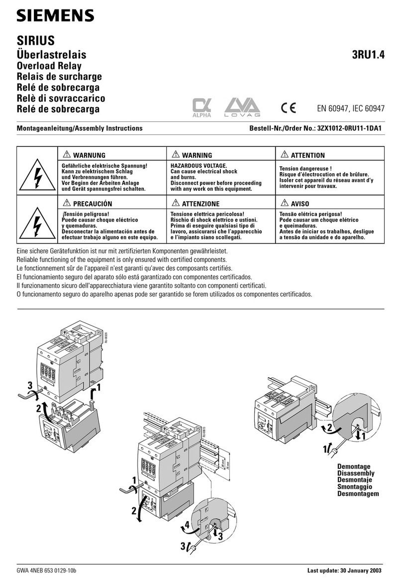
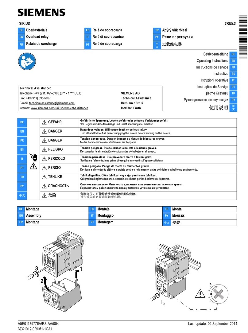
Siemens SIRIUS User manual

Siemens

Siemens SIRIUS User manual

Siemens 3RB22 User manual

Siemens

Siemens 3RB22 User manual

Siemens SIRIUS 3UG4815 Series User manual

Siemens

Siemens SIRIUS 3UG4815 Series User manual

Siemens 3UA60 User manual

Siemens

Siemens 3UA60 User manual

Siemens SITRANS LVL200H User guide

Siemens

Siemens SITRANS LVL200H User guide

Siemens SIRIUS 3SU140 1E Series User manual

Siemens

Siemens SIRIUS 3SU140 1E Series User manual

Siemens 5TT3426 User manual

Siemens

Siemens 5TT3426 User manual

Siemens SIRIUS 3RQ1 User manual

Siemens

Siemens SIRIUS 3RQ1 User manual

Siemens 3RP25 User manual

Siemens

Siemens 3RP25 User manual

Siemens 7UT51 User manual

Siemens

Siemens 7UT51 User manual

Siemens SIPROTEC4 7SJ61 User manual

Siemens

Siemens SIPROTEC4 7SJ61 User manual

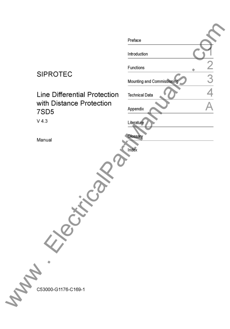
Siemens siprotec 7SD5 User manual

Siemens

Siemens siprotec 7SD5 User manual

Siemens 3TK2856 User manual

Siemens

Siemens 3TK2856 User manual

Siemens 3SK1120 Series User manual

Siemens

Siemens 3SK1120 Series User manual

Siemens 3TK2853 User manual

Siemens

Siemens 3TK2853 User manual

Siemens Argus 7SR11 User manual

Siemens

Siemens Argus 7SR11 User manual

Siemens 3RU7136 Series User manual

Siemens

Siemens 3RU7136 Series User manual

Siemens 3MU711 Series User manual

Siemens

Siemens 3MU711 Series User manual

Siemens SIPROTEC 7SJ80 User manual

Siemens

Siemens SIPROTEC 7SJ80 User manual

Popular Relay manuals by other brands

ENCARDIO RITE EWN-01R user manual

ENCARDIO RITE

ENCARDIO RITE EWN-01R user manual

ABB CM Series Operating and installation instructions

ABB

ABB CM Series Operating and installation instructions

Schweitzer Engineering Laboratories SEL-411L Application guide

Schweitzer Engineering Laboratories

Schweitzer Engineering Laboratories SEL-411L Application guide

Omron G9SX-EX401 Series user manual

Omron

Omron G9SX-EX401 Series user manual

Emirel W 04N quick start guide

Emirel

Emirel W 04N quick start guide

Sterling Power Pro Con CVSR Series quick start guide

Sterling Power

Sterling Power Pro Con CVSR Series quick start guide

Mighty Module MM1000A manual

Mighty Module

Mighty Module MM1000A manual

Eaton Digitrip 3000 series Installation, operation and maintenance instructions

Eaton

Eaton Digitrip 3000 series Installation, operation and maintenance instructions

SICK ReLy OSSD4 operating instructions

SICK

SICK ReLy OSSD4 operating instructions

Pilz PNOZ X2.1 operating manual

Pilz

Pilz PNOZ X2.1 operating manual

Ytc YT-325 Series product manual

Ytc

Ytc YT-325 Series product manual

CARLO GAVAZZI DPB01 manual

CARLO GAVAZZI

CARLO GAVAZZI DPB01 manual

Taco SR501-HC-4 instruction sheet

Taco

Taco SR501-HC-4 instruction sheet

Eaton EMT6 (230V) Instruction leaflet

Eaton

Eaton EMT6 (230V) Instruction leaflet

Pilz PNOZ X2C operating instructions

Pilz

Pilz PNOZ X2C operating instructions

Pilz PNOZ X11P operating manual

Pilz

Pilz PNOZ X11P operating manual

ABB COV-6 Instruction

ABB

ABB COV-6 Instruction

Ei Electronics Ei128R instruction manual

Ei Electronics

Ei Electronics Ei128R instruction manual

manuals.online logo
manuals.online logoBrands
  • About & Mission
  • Contact us
  • Privacy Policy
  • Terms and Conditions

Copyright 2025 Manuals.Online. All Rights Reserved.