Swegon Actionair ThermShield FD User manual

INSTALLATION GUIDE
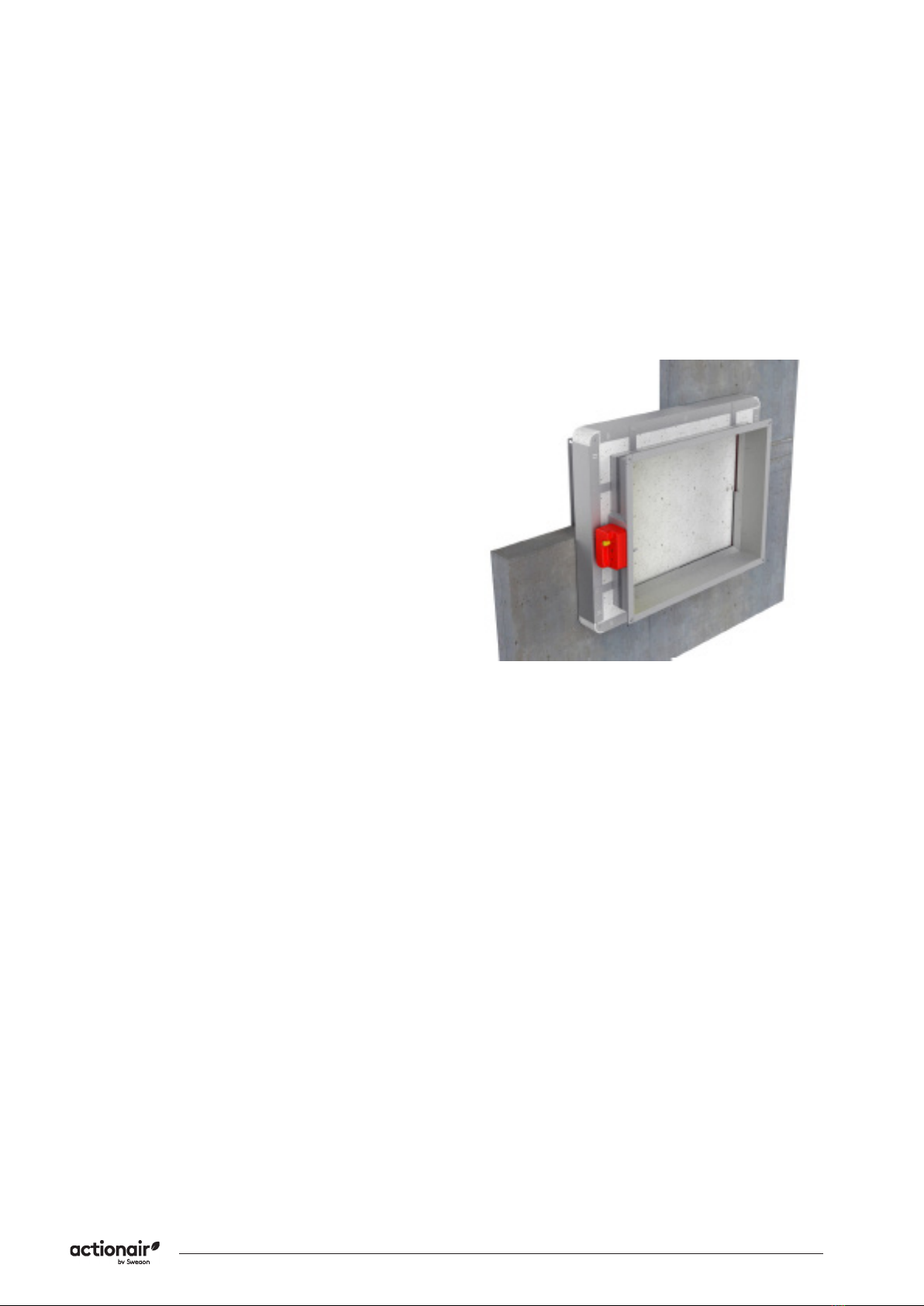
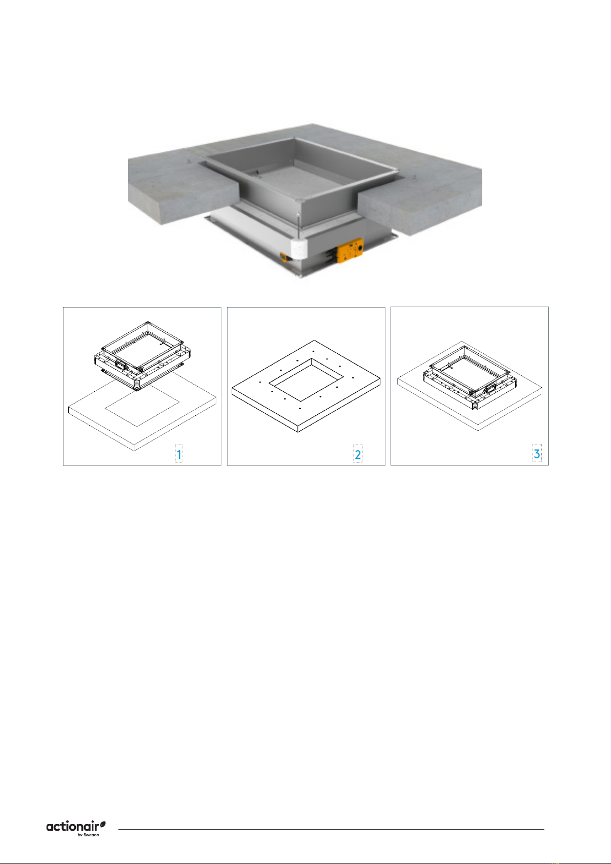
ThermShield MF On Wall/Floor Installation Method
Applies to...
• Actionair ThermShield FD
• Actionair Thermshield FD-C
Health and safety
• This process must be undertaken by competent
persons. More than one person may be required to
ensure the safe handling of large dampers and other
materials. Use must be made of access equipment
to ensure unsafe practices are not used to approach
• Standard site PPE should be used (minimum steel
toe cap boots, hard hat); together with any pro-
tective eyewear, gloves and masks, when drilling or
cutting is being undertaken. The latter should also
be used when handing the wall construction mate-
equipment is being used, hearing protection should
be used.
• All waste materials should be collected and disposed
• Actuators: All wiring should be carried out in accor-
and BS regulations and by a competent person.
Care must be taken when installing and inspecting
dampers, as they are likely to close without war-
ning due to loss of electrical power or a temperature
rise in the ductwork. This is their prime function. Do
blades. Larger dampers must be handled in accor-
dance with current regulations and good practice
due to weight.
Contents
Applies to................................................................................1
Health and safety..................................................................1
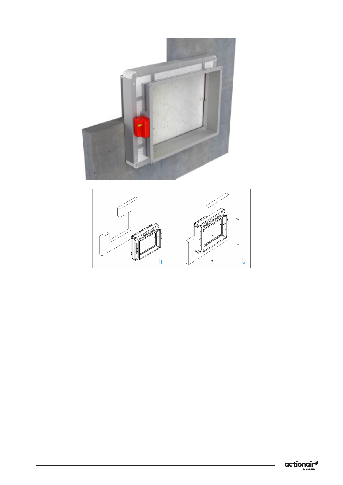
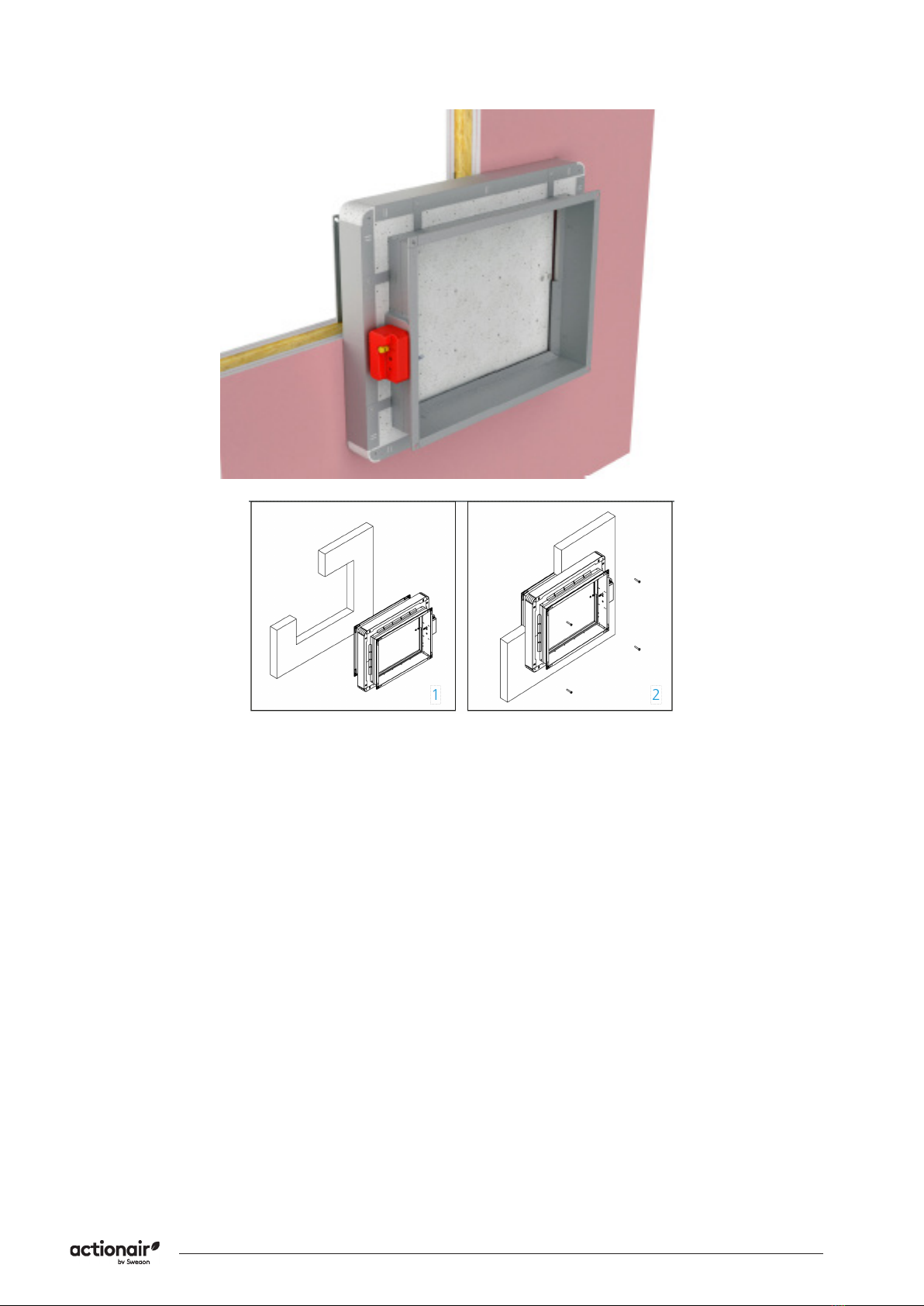
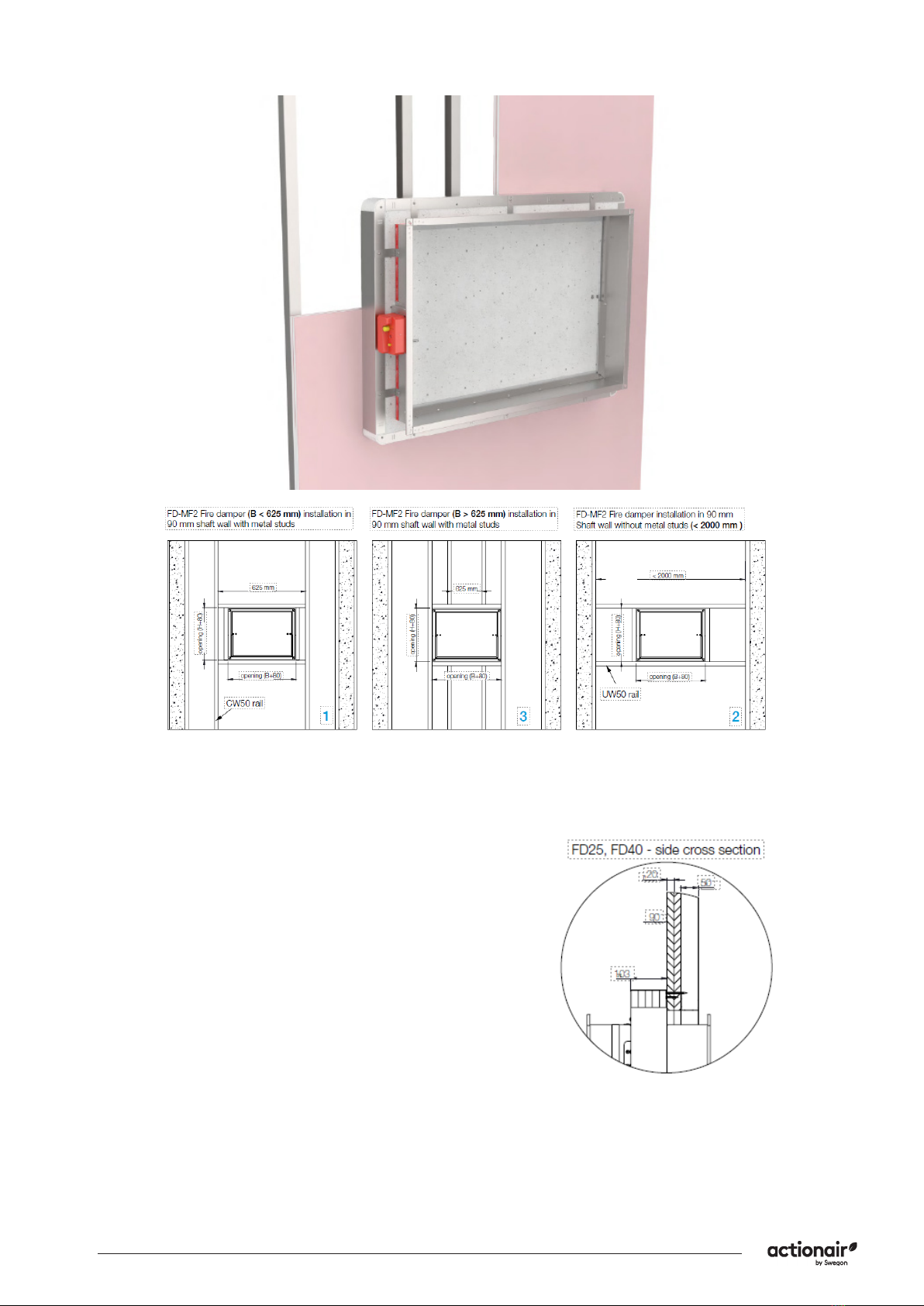
Fire damper installation square openings........................3
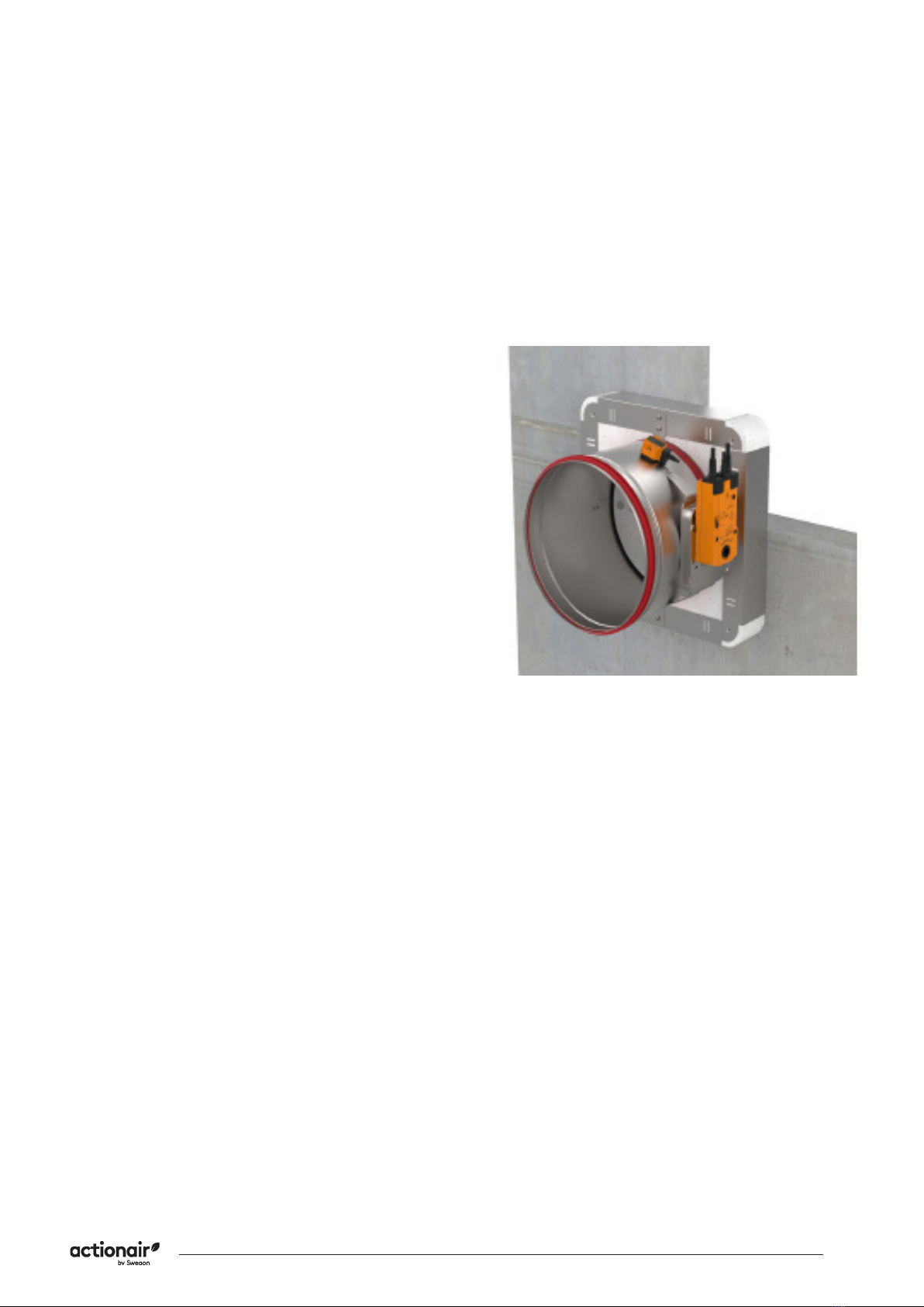
Fire damper installation circular openings.......................9
(circular)................................................................................10
Wiring Diagrams..................................................................19

ThermShield MF On Wall Installation Method
2Swegon reserves the right to alter specications. 20210615 - L00010
Application Installation Method
Rigid wall installation MF2 installation frame (square) Page 4
Flexible wall installation MF2 installation frame (square) Page 5
Sha wall installation MF2 installation frame (square) Page 6
Rigid oor/ceiling MF2 installation (square) Page 7
Rigid wall installation MF2 installation frame (circular) Page 10
Flexible wall installation MF2 installation frame (circular) Page 11
Sha wall installation MF2 installation frame (circular) Page 12
Rigid oor/ceiling MF2 installation (circular) Page 13
• For full classications please refer to our Declaration
of Performance (DoP), which can be found on our
website.
• The methods in this manual should be followed to
ensure a CE-marked installation.
• The instructions are based on the tested method using
Actionair ThermShield re/smoke dampers.
• Our ThermShield dampers are designed to be used with
re separating elements to maintain re compartments.
The ThermShield is an actuated failsafe close damper
with low smoke leakage.
• Under the Fire Damper Product standard BS EN 15650
our Fire Damper products are tested to BS EN 1366-2 and
classied under BS EN 13501-3.
CE Installation Method Overview

3
20210615 - L00010 Swegon reserves the right to alter specications.
ThermShield MF On Wall Installation Method
Fire damper installation
square openings
standardised support frames (both in a concrete wall
the one of the tests.
supported or hung in such a way that the damper
does not carry its weight. The damper must not
support any part of the surrounding construction
or wall which could cause damage and consequent
damper to a dilatation compensator on either end of
the damper.
The damper driving mechanism can be placed on
either side of the wall, however it needs to be placed
so as to ensure easy access during inspection.
• The installation must comply with the tests that
• Avoid any obstruction of the moving blade by the
connected ducts
• The class of air-tightness is maintained in case the
installation of the damper is made in accordance with
the technical manual
• For indoor use only
All dampers can be installed with the blade axis
in a horizontal position or a vertical position in all
installation types except installation remote from the
that the damper blade in its closed position is located
inside this structure.
Check the operation of the re damper before
commencing the installation.

ThermShield MF On Wall Installation Method
4Swegon reserves the right to alter specications. 20210615 - L00010
Rigid wall installation
MF2 installation frame
Damper blade must be closed during installation.
The wall is composed of concrete blocks (minimum
Data section.
Test the operation of the damper blade.

5
20210615 - L00010 Swegon reserves the right to alter specications.
ThermShield MF On Wall Installation Method
Flexible wall
installation MF2
installation frame
Damper blade must be closed during installation.
the mineral wool inside the wall (mineral wool with
Create an opening according to the dimension of
to the drawing.
Test the operation of the damper blade.

ThermShield MF On Wall Installation Method
6Swegon reserves the right to alter specications. 20210615 - L00010
Sha wall installation
MF2 installation frame
Damper blade must be closed during installation.
installed on to a peripheral frame made from galvanised
mm, make a steel subframe according to drawing
Test the operation of the damper blade.

7
20210615 - L00010 Swegon reserves the right to alter specications.
ThermShield MF On Wall Installation Method
Rigid oor/ceiling
MF2 installation frame
Damper blade must be closed during installation.
into the opening and mark the places for drilling
section.
Data section.
along with washer, nut and locking-nut on one side.
ceiling, and place the damper in the opening.
Tighten the tightening sets from oposite side with
washer, nut and locking-nut.
Test the operation of the damper blade.

ThermShield MF On Wall Installation Method
8Swegon reserves the right to alter specications. 20210615 - L00010
Flexible Wall Subframe
is necessary to make a metal subframe onto which the
prepared according to the drawings below.

9
20210615 - L00010 Swegon reserves the right to alter specications.
ThermShield MF On Wall Installation Method
Fire damper installation
circular openings
supported or hung in such a way that the damper
does not carry its weight. The damper must not
support any part of the surrounding construction
or wall which could cause damage and consequent
damper.
The damper driving mechanism can be placed on
either side of the wall, however it needs to be placed
so that it ensures an easy access during inspection.
Mounting is possible with the blade axis in horizontal or
in vertical position The installation must comply with
Avoid any obstruction of the moving blade by the
connected ducts
The class of air-tightness is maintained when the
installation of the damper is made in accordance with
the technical manual
For indoor use only.
rotation of the dampers blade is acceptable (with the
structure in such a way that the damper blade in its
closed position is located inside this structure (except
for installation with MF installation frame).
Check the operation of the re damper before
commencing the installation.

ThermShield MF On Wall Installation Method
10 Swegon reserves the right to alter specications. 20210615 - L00010
Rigid wall installation
MF2 installation
frame
Damper blade must be closed during installation!
The wall is composed of concrete blocks (minimum
Place the damper in the opening.
Test the operation of the damper blade.
21 3

11
20210615 - L00010 Swegon reserves the right to alter specications.
ThermShield MF On Wall Installation Method
Flexible wall
installation MF2
installation frame
Damper blade must be closed during installation.
wool inside the wall (mineral wool with density up to
mandatory to use the mineral wool inside the wall
subframe according to the drawing.
Test the operation of the damper blade.
21 3

ThermShield MF On Wall Installation Method
12 Swegon reserves the right to alter specications. 20210615 - L00010
Sha wall installation
MF2 installation frame
Damper blade must be closed during installation.
installed on to a peripheral frame made from galvanised
mm, make a steel subframe according to drawing
Test the operation of the damper blade!
* Dimension G depending of the damper type
is:
supported.
Test the operation of the damper blade.

13
20210615 - L00010 Swegon reserves the right to alter specications.
ThermShield MF On Wall Installation Method
Rigid oor/ceiling
installation MF2
installation frame
Damper blade must be closed during installation.
places for drilling holes.
along with washer, nut and locking-nut on one
side. Place pre-assembled threaded rods in holes in
Test the operation of the damper blade.

ThermShield MF On Wall Installation Method
14 Swegon reserves the right to alter specications. 20210615 - L00010
Flexible Wall Subframe
is necessary to make a metal subframe onto which the
prepared according to the drawings below.

15
20210615 - L00010 Swegon reserves the right to alter specications.
ThermShield MF On Wall Installation Method
Periodic Maintenance
Manufacturer Recommended Service
Intervals
•
we recommend that you follow a regular service and
inspection programme to ensure correct operation
of dampers in the event the damper is required to
actuate.
•
a dedicated damper control panel with a digital
system) to frequently monitor and report on regular
remote damper testing.
• Ensure maintenance is performed in line with the latest
best practice and relevant local or specialist guidance.
•
products are as follows:
Interval Action Competence
6 Months Check Actuator Wiring (if appli-
cable) for Damage
Specialist
Persons
6 Months Check Limit Switch Wiring (if
applicable) for Damage
Specialist
Persons
6 Months Check Damper Cleanliness, Clean
and Lubricate if necessary.
Specialist
Persons
6 Months Check Condition of Blades and
Seals, report and rectify if neces-
sary.
Specialist
Persons
6 Months Check for blade obstructions Specialist
Persons
6 Months Check Damper Release Me-
chanism (through activation or
release of the ETR or Thermal
Fuse Device)
Specialist
Persons
6 Months Check damper is left in normal
operational position after inspec-
tion.
Specialist
Persons
Monthly Complete actuation of damper
from control panel (if installed)
and check all faults. Consult
specialist persons to investigate
any reported faults.
Facility
Manager
• *Specialist Persons: A recognised and experienced
person with prior experience in the inspection and
technical support team for advice. To talk about our
service team.
BS EN 15650:2010 - Ventilation for Buildings
- Fire Dampers
•
be undertaken to meet regulatory requirements, or at
intervals not exceeding six months.
• A comprehensive example of the maintenance
procedure is given in Annex D of the standard. Some
automatic systems may allow more frequent testing
standard.
Approved Document B, Volume 2
•
must be provided to allow inspection, testing and
mechanism.
BS 9999:2017 - Code of Practice for the Fire
Safety in the Design, Management and Use of
Buildings - Annex I
Smoke Control Systems
• For means of escape states actuation of the system
that any fans and powered exhaust ventilators operate
correctly, smoke dampers close (or open in some
systems), natural exhaust ventilators open, automatic
smoke curtains move into position, etc.
Three Monthly
•
be simulated once every three months. All zones
should be separately tested and it should be ensured
that any fans and powered exhaust ventilators operate
correctly, smoke dampers close (or open in some
systems) etc.
Yearly
•
for annual inspections and tests of the following to
be carried out by competent persons, for any defects
to be logged and the necessary action taken, and for
–
–Self-contained luminaires with sealed batteries, if
–Sprinkler, drencher and watermist systems;
–Smoke ventilators and smoke control systems;
–Fire dampers
BS 9999:2017 - Code of Practice for the Fire
Safety in the Design, Management and Use of
Buildings - Annex W
• Maintenance of air conditioning and ventilation
and their controls, smoke detectors and alarms is
and in ensuring that measures taken to mitigate
be tested by a competent person on completion of the
years. They are to be repaired or replaced immediately
laden and similar atmospheres should be tested much
more frequently, at periods suited to the degree of
pollution.

ThermShield MF On Wall Installation Method
16 Swegon reserves the right to alter specications. 20210615 - L00010
Actuators
Manual Actuators R, R-S
Manual operating mechanism, optionally with end swit-
ches (R-S). In case of re, the re damper closes automa-
tically. Damper closing can be initiated either by thermal
fuse melting, or by manual activation on the operating
mechanism. Upon closure, damper blade is locked in
closed position and can only be opened manually. Ther-
mal fuse melting point is 72 °C.
R25
R25 (left) manual actuator is installed on FD25 re dam-
pers range from 100x200 to 800x600. It is available in
version with (R-S) and without (R) end switches. End swit-
ches and thermal fuse are easily replaceable and available
as service parts.
R40
R40 (right) manual actuator is installed on FD40 re dam-
pers from 800x600 to 1500x800. It is available in version
with (R-S) and without (R) end switches. End switches and
thermal fuse are easily replaceable and available as service
parts.
Technical Specications
Nominal voltage N/A
Power N/A
Switching capacity 1mA…500mA, 5VDC…48VDC
Blade closing time Spring: 1 sec
Blade opening time Manual
Manual activation Release button on the casing
Degree of protection IP 42
Ambient temperature
range min. -30 °C, max. 50 °C
Ambient humidity 95% r.h.,
non-condensing
Service life Min. 30,000 cycles
Maintenance Maintenance-free (see page 20)
Weight R25/R40 0,5 kg / 1,7 kg

17
20210615 - L00010 Swegon reserves the right to alter specications.
ThermShield MF On Wall Installation Method
Electric Actuators M24-S & M230-S
Damper is delivered in closed position. When electric
actuator is connected to the power supply damper
will open. When the damper reaches the end position
(damper open), the electro motor will stop. Closing re
damper takes place automatically when a power failure
occurs. Thermal tripping device that comes with re
damper causes power circuit break at a temperature of 72
°C, optional 95 °C (inside or outside duct). If checking is
needed for proper functioning of re damper, pushing the
switch on the thermal tripping device will close damper.
When switch on tripping device is released, the damper
will open. Damper can be opened without connecting to
a voltage with enclosed handle turning in the direction of
the arrow on electric actuator (clockwise). Damper can be
locked in the desired position by fast turning back handle
a quarter of a turn (counter clockwise) for Belimo BF, and
by puling brake on Belimo BFL and BFN.
To unlock the electro motor, turn handle clockwise for
a quarter of a turn for Belimo BF, or release brake for
Belimo BFL and BFN. After release, damper will be closed
by return spring. When damper is opened manually, elec-
tric actuator will not move the damper into closed posi-
tion in case of power failure.
Technical Specications
Type of Belimo actu-
ator BFL24-T BFN24-T BFL230-T BFN230-T BF24-T BF230-T
Nominal
voltage /
power
consump-
tion
voltage
AC/DC 24
V, 50/60
Hz
AC 24 V,
50/60 Hz
AC 230 V,
50/60 Hz
AC 230 V,
50/60 Hz
AC/DC
24 V,
50/60 Hz
AC 230
V, 50/60
Hz
opening 2,5 W 4 W 3,5 W 5 W 7 W 8.5 W
holding 0,8 W 1,4 W 1,1 W 2,1 W 2 W 3 W
for wire
sizing 4 VA 6 VA 6,5 VA 10 VA 10 VA 11 VA
End switch
1 mA...3
A (0,5 A),
DC 5 V...
AC 250V
1 mA...3
A (0.5
A), DC
5 V...AC
250 V
1 mA...3
A (0.5 A),
DC 5 V...
AC 250 V
1 mA...3 A
(0.5 A), DC
5 V...AC
250 V
1 mA...6
A (3 A),
DC 5 V...
AC 250
V
1 mA...3
A (0.5
A), DC
5 V...AC
250 V
Running
time
motor < 60 s < 60 s < 60 s < 60 s < 120 s < 120 s
spring
return ~ 20 s ~ 20 s ~ 20 s ~ 20 s ~16 s ~16 s
Ambient temperature
range min. -30 °C, max. 50 °C

ThermShield MF On Wall Installation Method
18 Swegon reserves the right to alter specications. 20210615 - L00010
Electric Actuator Schischek ExMax
Damper is delivered in closed position. When electric
actuator is connected to the power supply damper will
open. When the damper reaches the end position(damper
open), in which is it blocked, the electric actuator will
stop. Closing re damper takes place automatically when
a power failure occurs. Thermal tripping device that
comes with re damper causes power circuit break at a
temperature of 72 °C (inside or outside duct).
If checking is needed for proper functioning of re
damper, pushing the switch on the thermal tripping
device will close damper. When switch on tripping device
is released, the damper will open.
Damper can be opened without connecting to a voltage
with enclosed Allen key, by turning in the direction of the
arrow on electric actuator (clockwise). After release of
Allen key, damper will go to closed position.
Type Examination Certicate Number: EXA 14
ATEX0064X Equipment complies with the essential
health and safety requirements relating to the design and
construction of equipment intended to use in potentially
explosive atmospheres given in annex II of the directive
94/9/EC.
Technical Specications
Type ExMax -5.10-BF ExMax -15-BF
Torque 5/10 Nm 15 Nm
Power Supply 24-230 V AC/DC 24-230 V AC/DC
Running time 3/15/30/60/120 s / 90° 3/15/30/60/120 s / 90°
Spring return 3 or 10s / 90° 3 or 10s / 90°
Control mode On-O, 3 position On-O, 3 position
Feedback 2 x aux switches + Ex. tripping
device
2 x aux switches + Ex. tripping
device
Ambient temperature
range min. -40 °C, max. 40 °C min. -40 °C, max. 40 °C
Ambient humidity 0-90% r.h.,
non-condensing
0-90% r.h.,
non-condensing
Service life Min. 10,000 cycles @ 10 s, min
1000 cycles @ 1s
Min. 10,000 cycles @ 10 s, min
1000 cycles @ 1s
Maintenance Maintenance-free Maintenance-free
Weight 3,5 kg 3,5 kg

19
20210615 - L00010 Swegon reserves the right to alter specications.
ThermShield MF On Wall Installation Method
Wiring Diagrams
Manual Actuators R, R-S
FC = Limit switch - end
DC = Limit switch - start
NO = normally open
NF = normally closed
C = common
FC DC
NF NO CNF NO C
11 12 13 14 15 16
1 negative (direct-current) or neutral (alternating current)
2 positive (direct-current) or faze (alternating current)
S1 common micro switch closed damper
S2 normally closed micro switch closed damper
S3 normally open micro switch closed damper
S4 common micro switch open damper
S5 normally closed micro switch open damper
S6 normally open micro switch open damper
Tf temperature sensor on the outer side of the duct (ambient
temperature) max. 72 °C
Electric Actuator M24-S & M230-S

ThermShield MF On Wall Installation Method
20 Swegon reserves the right to alter specications. 20210615 - L00010
H < 300
Thermal fuse is located on the
underside of the re damper.
300 ≤ H ≤ 450
Thermal fuse is located on the
same side as Belimo actuator.
H > 450
Thermal fuse is located on the same
side as Belimo actuator (below).
Bottom View Side view Side view
Electric Actuator Schischek ExMax
Other manuals for Actionair ThermShield FD
1
This manual suits for next models
11
Table of contents
Other Swegon Fire And Smoke Damper manuals

Swegon
Swegon actionair FireShield User manual

Swegon
Swegon SAFEGARDSYSTEMS FD 25 User manual

Swegon
Swegon Actionair A60 User manual

Swegon
Swegon REACT Pa User manual

Swegon
Swegon Actionair SmokeShield PTC User manual

Swegon
Swegon actionair DWFX-F User manual

Swegon
Swegon BLBd Guide

Swegon
Swegon Actionair A60 User manual

Swegon
Swegon Actionair ThermShield FD User manual

Swegon
Swegon Actionair CSS Series User manual