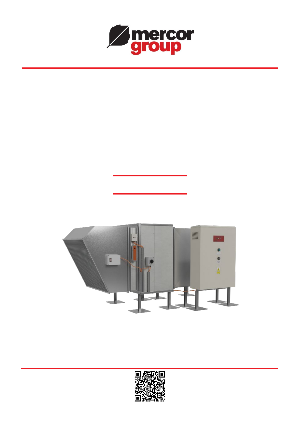
mercor mcr EXi-F User manual

FIRE VENTILATION SYSTEMS DEPARTMENT
OPERATION AND
MAINTENANCE MANUAL
Hybrid smoke prevention
system for evacuation routes
mcr EXi-F
mcr EXI-F 23.07.28.1 version

OMM - mcr EXi-F
Version mcr EXI-F 23.07.28.1 Page 2/99
CONTENTS
1. INTRODUCTION INTO TRADING ........................................................................................................4
2. FOREWORD .....................................................................................................................................5
3OBJECT OF THE DOCUMENTATION ..................................................................................................5
4INTENDED PURPOSE OF THE DEVICE..............................................................................................5
4.1 Application ......................................................................................................................................5
4.2 System elements ............................................................................................................................5
4.3 System mode of operation ..............................................................................................................5
4.4 System selection principle ..............................................................................................................7
4.4.1. Requirements of the EN 12101-13 standard ......................................................................................8
4.4.2. Requirements in the Manual no. 378/2002 of the Construction Technology Institute.......................9
4.4.3. Requirements concerning the design of a fire ventilation system.................................................11
5. SYSTEM COMPONENTS..................................................................................................................12
5.1. Design of the mcr EXi-F air supply unit.........................................................................................12
5.1.1. Fan................................................................................................................................................16
5.1.2. Shut-off damper (non-insulated/insulated)...................................................................................17
5.1.3. Service disconnector.....................................................................................................................18
5.1.4. Vibration and noise dampening elements (optional)......................................................................18
5.1.5. Installation feet (optional) .............................................................................................................19
5.1.6. LAM louvered vents (optional) ......................................................................................................19
5.2. Explosion pressure relief panels (PL, PLD) and system permanent unsealing module (PRC)
(optional)................................................................................................................................................20
5.3. mcr OMEGA control panel .............................................................................................................23
5.3.1. Description and principle of operation ..........................................................................................23
5.3.2. Signaling .......................................................................................................................................25
5.3.3. Specifications................................................................................................................................25
5.3.4. mcr ICR pro positive pressure regulator.......................................................................................27
5.4. mcr ICS pro differential pressure transmitter...............................................................................28
5.5. mcr PSR / mcr PSRC manual control panel ..................................................................................30
5.6. mcr WPS elevated control panel ...................................................................................................31
5.7. Duct smoke detector .....................................................................................................................32
5.8. Intake vent switching system........................................................................................................33
5.9. mcr ICP lobby controller ...............................................................................................................34
5.10. mcr PP connection box .................................................................................................................37
5.11. Damper for lobby systems ............................................................................................................38
5.12. mcr HT anti-icing system ..............................................................................................................39
5.13. mcr SEP network separators........................................................................................................41
5.14. Temperature transmitter...............................................................................................................42
5.15. Magnetic sensors (reeds)..............................................................................................................43
5.16. Differential pressure switch..........................................................................................................43
6. ELECTRICAL CONNECTION............................................................................................................44
6.1. Electrical connections of devices to the mcr Omega panel ...........................................................62
6.1.1. EXI-F unit air supply fan................................................................................................................62
6.1.2. Service disconnector.....................................................................................................................63
6.1.3. Shut-off damper............................................................................................................................63
6.1.4. mcr PLD explosion pressure relief panels....................................................................................64

OMM - mcr EXi-F
Version mcr EXI-F 23.07.28.1 Page 3/99
6.1.5. mcr RPC system permanent unsealing module.............................................................................64
6.1.6. Connection of the mcr Omega control panel from FSS..................................................................65
6.1.7. Connection diagram for automation with backup fan ....................................................................66
6.1.8. Automation connection diagram for vertical fans..........................................................................67
6.1.9. Automation connection diagram for switching system / double intake vent..................................68
6.1.10. Automation connection diagram for lobby system ........................................................................68
6.1.11. mcr ICS pro differential pressure transmitter...............................................................................73
6.1.12. mcr PSR / mcr PSRC manual control panel ..................................................................................74
6.1.13. mcr WPS elevated control panel ...................................................................................................75
6.1.14. Duct smoke detector .....................................................................................................................75
6.1.15. mcr HT anti-icing system ..............................................................................................................76
6.1.16. Connection of mcr EXi-F actuators ...............................................................................................76
6.1.16.1. Actuators with return spring....................................................................................................76
6.1.16.2. Actuators without return spring ...........................................................................................77
6.1.16.3. High-speed actuators for the mcr ICP lobby regulator .........................................................77
7. PNEUMATIC CONNECTION.............................................................................................................77
7.1. Connection of a mcr ICS pro differential pressure transmitter .....................................................79
7.2. Connecting the mcr ICP lobby regulator........................................................................................80
8. MECHANICAL CONNECTION OF SYSTEM COMPONENTS................................................................81
8.1. mcr Monsun air supply units.........................................................................................................81
8.2. Control panel mcr Omega .............................................................................................................84
8.3. mcr ICS pro differential pressure transmitter...............................................................................84
8.4. mcr PSR / mcr PSRC manual control panel ..................................................................................85
8.5. Duct smoke detector .....................................................................................................................85
8.6. mcr ICP lobby regulator ................................................................................................................86
8.7. mcr PP connection box .................................................................................................................86
8.8. Magnetic sensors (reeds)..............................................................................................................87
8.9. Differential pressure switch..........................................................................................................88
9. ACTIVATION OF THE MCR EXI-F SYSTEM .......................................................................................88
9.1. mcr EXi-F application....................................................................................................................89
9.2. Commissioning, adjustments, measurements...............................................................................90
9.2.1. Guidelines .....................................................................................................................................90
9.2.2. Most common errors.....................................................................................................................92
10. SYSTEM ELEMENTS MARKING SCHEME........................................................................................96
11. TRANSPORT AND STORAGE CONDITIONS......................................................................................97
12. MAINTENANCE AND SERVICE .......................................................................................................98
13. WARRANTY AND GUARANTEE CONDITIONS ..................................................................................98
CAUTION:
•The Company reserves the right to introduce modifications and changes.
•As of the date of issue of the operation and maintenance documentation, the previous version are
invalidated.
•The operation and maintenance manual does not apply to devices manufactured prior to its issue date.

OMM - mcr EXi-F
Version mcr EXI-F 23.07.28.1 Page 4/99
1. INTRODUCTION INTO TRADING
The EXi-F hybrid smoke prevention system for evacuation routes has been introduced into trading
based on documents issued by the Instytut Techniki Budowlanej (Construction Technology Institute) and
a national declaration of performance:
1. National Technical Assessment ITB-KOT-2021/1788 issue 2
2. National Certificate of Constancy of Performance 020-UWB-2469/W
3. National Declaration of Performance HW/01/2021

OMM - mcr EXi-F
Version mcr EXI-F 23.07.28.1 Page 5/99
2. FOREWORD
The purpose of this operation and maintenance manual is to inform the user about the designated
use, design, mode of operation, correct installation and handling of the product.
The OMM also contains additional information about the conditions for use, maintenance and guarantee
conditions for the product.
Prior to starting installation and operation of the device, this OMM must be reviewed in detail. Failure
to follow the recommendations included in the documentation may lead to dangerous situations, damage
to property and/or injuries. The manufacturer shall not be responsible for damage resulting from use
that is inconsistent with this documentation.
3OBJECT OF THE DOCUMENTATION
This OMM relates to the entire group of devices constituting the mcr EXI-F hybrid smoke prevention
system for evacuation routes. Observing the recommendations included in the OMM shall ensure the
correct functioning of the device within the scope of fire protection for rooms and the safety of system
users.
4INTENDED PURPOSE OF THE DEVICE
4.1 Application
The mcr EXi-F system is used to protect any protected area (staircases, elevator shafts, lobbies,
evacuation corridors) against smoke by creating overpressure. The system is made up of appropriately
configured device sets that cooperate and prevent the penetration of smoke into the protected space by
creating higher overpressure. Depending on the individual needs, air supply to the protected space may
be ensured using a single-point or multi-point air supply. Device sets are appropriate for indoor and
outdoor operation, can operate in a vertical or horizontal fan operating position, depending on the ordered
version (installation on roofs, in walls etc.).
4.2 System elements
The mcr EXI-F system includes, but is not limited to elements such as:
•air supply unit(s) with additional equipment (dampers, intake vents, exhaust vents etc.),
•mcr Omega power supply and control panel,
•mcr ICR pressure regulator (mcr Omega panel component),
•mcr ICS and mcr ICP differential pressure transmitter(s).
Auxiliary system components may include:
•mcr PSR manual control panel
•U2 intake vent switching system,
•duct smoke detectors,
•WPS elevated control panel,
•mcr PL and mcr PLD explosion pressure relief panels,
•mcr RPC system permanent unsealing module.
4.3 System mode of operation
Operation of the mcr EXi-F system is controlled by the mcr Omega power supply and control panel.
The overpressure system is activated automatically by means of a signal from FSS. Once a signal
confirming that a fire was detected in the building is sent, the following activities are performed:
• opening dampers at air supply units,
• opening air exhaust elements for the usable floor space on the level affected by the fire,
• activation of air supply units,

OMM - mcr EXi-F
Version mcr EXI-F 23.07.28.1 Page 6/99
• opening the system permanent unsealing module (if included).
Several seconds after a fire is detected, the protected space is filled with air, creating a pressure
difference between this space and the adjacent rooms. The required amount of overpressure is
controlled by supplying a variable amount of air to the protected zone using one or more air supply units.
Figure 1mcr EXi-F system schematic diagram.
Where the door to the protected zone is closed, the fan, which is the main element of the air supply
unit, delivers the necessary stable air volume. Measurement and control of the current pressure value
in the protected space is ensured via one or more pressure transmitters. The overpressure created in
the protected space at the assumed level guarantees that the force necessary to open the evacuation
door does not exceed 100 N. Opening the door causes a pressure drop in the protected zone, which
increases the fan rpm (system response time below 3 seconds) and ensures the appropriate design air
flow value through the open door separating the protected zone from the adjacent space. In order for the
required air flow velocity through the open door to achieve the desired value, it is necessary to ensure
air relief into the surroundings, e.g. via one or a combination of the following solutions:
•an opening in the external wall (e.g. automatically opened windows – mcr OSO, grilles),
•air vent shaft equipped with fire dampers (e.g. mcr FID S,
mcr WIP PRO) at the outlet from each level,
CORRIDOR
VESTIBULE
STAIRCASE
ELEVATOR
air supply unit with damper and smoke detector
mcr RPC protected space unsealing module (optional)
mcr Omega control panel(s)
differential pressure transmitter
air relief
pressure measurement point located in the external area
pressure measurement point located in the usable floor space
PSR manual control panel
WPS elevated control panel
air flow direction
cabling

OMM - mcr EXi-F
Version mcr EXI-F 23.07.28.1 Page 7/99
•mechanical exhaust, properly designed and controlled, terminated with a smoke exhaust fan (e.g.
mcr Pasat or mcr Monsun).
A shut-off damper is one of the elements of an air supply unit. While the system is in standby, the
damper remains closed and prevents the staircase from seeping heat. The damper is opened in case of
a fire alarm. The air supply unit system may be additionally equipped with a duct smoke detector. Should
the detector identify smoke in the vented air, the fan is stopped and the damper is closed. When the air
inlet is located on the roof, according to the guidelines in the standard [1], two opposing intake vents
should be used, each equipped with a damper and smoke detector, unless the design stipulates
otherwise. Should the smoke detector identify that the air is contaminated with smoke, the intake vent
with smoke is shut off and the damper on the opposing air inlet is opened (U2 double intake vent system).
The throughput of the air supply unit that protects a particular space against smoke is determined by
the designer. When selecting the air supply unit for each certified overpressure system, check the
minimum unit throughput condition. This value determines the minimum required leakage in the
protected space to ensure that the system's proper operation conditions are met (maximum reaction
time to conditions changing during the evacuation). In protected sealed spaces that require high air
supply units throughput values (e.g. staircase with a small number of large doors), the leakage surface
may prove to be too small compared to what is required. In such a case the protected area should be
additionally "unsealed". The unsealing function may be provided by any opening in the external wall or
roof of the space protected against smoke. It is recommended for the unsealing opening to be closed
during normal use, to prevent the room from seeping heat, and it should only be opened as a result of a
fire alarm.
The following may be used as system unsealing modules in the mcr EXi-F system:
•roof exhaust vent with a multi-blade damper with an mcr RPC fire-rated actuator,
•mcr LAM louvered vent.
Where achieving the required operating parameters of the system is difficult, it is recommended to
use mcr PL, mcr PLD explosion pressure relief panels with the appropriate actuation threshold.
4.4 System selection principle
In Poland, the design of systems preventing smoke accumulation in vertical and horizontal evacuation
routes is based on the following:
•EN 12101-13 standard "Smoke and heat control systems. Part 13: Pressure differential systems
(PDS). Design and calculation methods, installation, acceptance testing, routine testing and
maintenance." [1]
•Manual no. 378/2002 of the Construction Technology Institute "Designing fire ventilation systems
for evacuation routes in high and high-raise buildings". [2]
The designer is also authorized to design based on his own technical expertise and in agreement with
an expert in the field of fire protection they can adopt individual design criteria for a particular building.
Irrespective of the technical assumptions made, each of the smoke control systems should ensure the
following:
•required overpressure,
•pre-determined minimum air flow velocity in open doors,
•maximum allowed evacuation door opening force.

OMM - mcr EXi-F
Version mcr EXI-F 23.07.28.1 Page 8/99
4.4.1. Requirements of the EN 12101-13 standard
The standard [1] sets apart two pressure differentiation system classes (Class 1 and Class 2) that
differ in terms of the design requirements and conditions. The following table presents the typical
applications of system classes based on building purpose.
Requirements for the individual types of buildings
System class Building type
1
•in buildings with automatic fast response water sprinkler extinguishing
systems with a response time index (RTI) ≤
50 that are triggered by
temperatures ≤72 °C or
•
in residential buildings below the limits for tall buildings (in accordance
with national requirements) or
•
in residential buildings with at least two areas without fire load
between the protected space and the potential fire source and equipped
with self-locking doors or
•if Class 1 was accepted by competent authorities
2
•
if the requirements for Class 1 are not adequate or not applicable or
•
in buildings without automatic fast response water sprinkler
extinguishing systems or
•if required by competent authorities.
Once the proper classification of the building has been determined, a system that would meet the
requirements for the particular class is to be designed. The following table presents the design criteria
for the individual system classes. These requirements are decisive for the air supply unit throughput.
Parameter
Class 1
Class 2
Door opening force
≤100 N
Pressure difference
≥30 Pa
Airflow velocity
≥1 m/s
≥2 m/s
Activation time
≤60 s
Operating time
≤120 s
Response time
≤5 s
The designed system should ensure a pressure difference of at least 30 Pa between the protected
space and unprotected space on the floor where a fire has appeared. This requirement must be met
when:
•all doors in the protected staircase along with the exit doors are closed and
•all doors to the elevator shaft with increased pressure, except for a single access door, are closed
and
•the air exhaust vent from the staircase space is open and operational.
Where the doors between the protected space are open, the pressure difference criterion is replaced
with air flow criteria, as per the table above. Where more than one door leads from a protected space to
an unprotected space, it should be noted that the PDS system will only work with one door fully open,
assuming, in the case of doors with different dimensions, that it would be the door with the largest
surface area. In the case of double-leaf doors it is assumed that the bigger leaf is open. The velocity
criterion should be met on the floor where the fire occurred.

OMM - mcr EXi-F
Version mcr EXI-F 23.07.28.1 Page 9/99
Air supply to the staircase should be distributed evenly over the entire height of the staircase via a
vertical shaft. Air supplies should be located at least on every third level, unless the design indicates that
a smaller number of supplies will ensure the required throughput. Air supplies should not be located
near doors and the air stream velocity should not exceed 5 m/s.
Overpressure in the fire elevator shaft cannot negatively impact its operation. Should smoke
penetrate into the common, unprotected hallway, the pressure difference between the staircase and
hallway and between the elevator shaft and hallway cannot force the smoke to flow into the staircase or
elevator shaft. The above condition may be fulfilled by means of:
•limiting the air supply velocity into the shaft up to a maximum of 3 m/s or
•placing the air inlet in the upper part of the shaft or
•placing the air inlet in the lower possible location.
4.4.2. Requirements in the Manual no. 378/2002 of the Construction
Technology Institute
The manual [2] mentions two systems for protecting evacuation routes, designated as solution A and
B. These solutions are based on protecting the staircase and smoke-stop lobbies against smoke and
ensuring smoke exhaust ventilation for the evacuation corridor.
The table below presents the design criteria for these systems.
Protecting a staircase from against accumulation of smoke
System class
Conditions
Solution A
The smoke prevention system is to ensure:
1. A pressure difference of 20 ÷ 80
Pa between the staircase and corridor,
assuming that:
- all
doors between the staircase with increased pressure and the lobbies are
closed,
- the exit door is closed.
2. Air velocity not less than 0.5 m/s:
-
through the open door of the staircase at the level where the fire occurred,
where the smoke-stop lobby door is also open,
-through the staircase exit door.
Solution B As above
Protecting a smoke-stop lobby against accumulation of smoke
System class
Conditions
Solution A
1. Air supply to the lobby with a throughput of ≥720 m3/h/m2 of the lobby.
2. Mechanical exhaust from the lobby with a throughput of ≤90% of the supply.
3.
Pressure differentiation in the lobby compared to the staircase and
evacuation corridor where the lobby door is closed.
Solution B
1. Air supply to the lobby with a throughput ensuring an air flow velocity
through the open lobby door between the lobby and the evacuation corridor
at a level of 1.0
m/s (accounting for air supply through the open door
between the staircase and lobby).
2.
Air flow from the lobby to the corridor via transfer dampers installed in the
wall between the lobby and the corridor.
3.
Air velocity in the open door between the lobby and the corridor at least
1 m/s while the door between the staircase and lobby is open.
4.
Pressure differentiation in the lobby compared to the staircase and
evacuation corridor where the lobby door is closed.

OMM - mcr EXi-F
Version mcr EXI-F 23.07.28.1 Page 10/99
Smoke ventilation of evacuation corridors
System class
Conditions
Solution A
1. Direct air supply to the corridor. Air velocity ≤5 m/s. Minimum supply
airflow 3600 m3/h.
2. Smoke extraction system throughput ≥130% of the supply throughput.
3.
Ensuring a distance between the smoke ventilation and air supply grilles
as per the ITB Manual.
Solution B
1. Indirect air supply from the lobby to the corridor via a transfer damper in
the wall between the lobby and corridor. Air velocity at the damper ≤5 m/s.
2. Smoke extraction system throughput ≥130% of the supply throughput.
3.
Ensuring a distance between the smoke ventilation and air supply grilles
as per the ITB Manual.
Protecting an evacuation lobby against accumulation of smoke
System class Conditions
Solution A
1. Mechanical exhaust system with a throughput of no less than 3600 m3/h
per each 100 m2 of the lobby surface area. In no case less than 5400 m3/h.
2. Air supply system depending on the lobby height:
a) h ≤5 m
- mechanical air supply,
- air supply throughput 30% less than the exhaust throughput.
b) H ≥5 m
- gravitational air supply,
- air supply openings size selected based on the flow, no more than 5
m/s at
the air supply grille.
Solution B As above
Protecting an elevator shaft against accumulation of smoke
System class Conditions
Solution A
Pressure difference between the
emergency services elevator shaft and the
usable floor space should be approximately 50 Pa.
Solution B
Figure 2Design requirements diagram for solutions A and B.
SOLUTION A
SOLUTION B
throughput
≥
130% of the
air supply
throughput
throughput
≥
130% of the
air supply
throughput
air velocity
≤
5 m/s
throughput min.
3600 m3/h
air supply
≥
720 m3/h/m2 of
the lobby
staircase air
supply
staircase air
supply
STAIRCASE
STAIRCASE
LOBBY
LOBBY
CORRIDOR
CORRIDOR
air velocity
≤
5 m/s
exhaust
≥
90% of
supply
≥
0.5 m/s
≥
0.5 m/s
≥
1.0 m/s

OMM - mcr EXi-F
Version mcr EXI-F 23.07.28.1 Page 11/99
4.4.3. Requirements concerning the design of a fire ventilation system
The standard [1] and Manual [2] determine the requirements that a fire ventilation system should meet.
The following table presents the basic guidelines that are to be taken into consideration when designing
the system.
Air supply points for the staircase
Condition PN-EN 12101-13:2022
ITB Manual
no. 378/2002
Regardless of building height
Multi-point air supply at least
every 3 levels, unless the design
indicates that a smaller number
of air supply points will ensure
the required throughput
Single-point air supply may be
used
Air supply points for the elevator shaft
Condition PN-EN 12101-13:2022
ITB Manual
no. 378/2002
Regardless of shaft height
Single-point air supply may be
used
Single-point air supply may be
used
Location of the air supply unit
Condition PN-EN 12101-13:2022
ITB Manual
no. 378/2002
Roof-mounted unit
Two air inlets facing in different directions
are necessary (double intake vent system).
Every inlet should independently provide full
air supply as required by the system. Inlets
protected with a damper and equipped with
duct smoke detectors. If one inlet is
contaminated with smoke, the system
switches to the other intake vent.
The smoke exhaust vent should be located at
least 1 m above the air intake vent, at a
distance of at least 5 m.
No requirements determined.
A single intake vent is
admissible.
Unit on other levels
In the case of wall-mounted intake vents a
single air inlet equipped with a damper and
duct smoke detector is required.
No requirements determined.
Evacuation of air from the usable floor space in order to ensure air exhaust outside the building
Condition PN-EN 12101-13:2022
ITB Manual
no. 378/2002
Gravity vent
Windows equipped with
automatic control elements,
gravitational shafts/ducts may
be used
The manual does not include the
application of a gravity vent.
Mechanical vent
Active air exhaust, smoke
exhaust fan of the proper class
may be used.
A mechanical smoke exhaust
system is mandatory.

OMM - mcr EXi-F
Version mcr EXI-F 23.07.28.1 Page 12/99
5. SYSTEM COMPONENTS
5.1. Design of the mcr EXi-F air supply unit
mcr EXi-F system air supply units include the following products:
•mcr Monsun E1 fan in a box-type housing
•automation system in the form of a mcr Omega control panel
•multi-blade damper or LAM vents with actuator
•flexible connection (optional)
•duct smoke detector (optional)
•service disconnector (optional)
•anti-icing system (optional).
Figure 3Design of the mcr mcr EXi-F air supply unit (horizontal version).
Figure 4Design of the mcr mcr EXi-F air supply unit (UP vertical version).

OMM - mcr EXi-F
Version mcr EXI-F 23.07.28.1 Page 13/99
Figures 5 to 10 present the installation of sample air supply installations for mcr EXi-F systems.
Figure 5Sample installation of an air supply kit for the mcr EXi-F system: 1 - fan, 2 – damper with
actuator, 3 – service disconnector or connection box, 4 - flexible connection, 5 duct smoke detector, 6 –
inlet nozzle with grate.
Figure 6Sample installation of an air supply kit for the mcr EXi-F system in the duct version: 1 - fan, 2 –
damper with actuator, 3 – service disconnector or connection box, 4 - flexible connection, 5 duct smoke
detector.

OMM - mcr EXi-F
Version mcr EXI-F 23.07.28.1 Page 14/99
Figure 7Sample installation of an air supply kit for the mcr EXi-F system in the UP version on the roof: 1
- fan, 2 – LAM vent with actuator, 3 – service disconnector or connection box, 4 – roof base, 5 - duct
smoke detector.
Figure 8Sample installation of an air supply kit for the mcr EXi-F system in the wall-mounted version
indoors: 1 - fan in a box-type housing, 2 – damper with actuator, 3 – service disconnector or connection
box, 4 – lead, 5 - duct smoke detector, 6 – inlet nozzle with grate, 7 - supporting structure.

OMM - mcr EXi-F
Version mcr EXI-F 23.07.28.1 Page 15/99
Figure 9Sample installation of an air supply kit for the mcr EXi-F system in the roof-mounted version
with a double air intake vent system: 1 - fan, 2 – intake vent, 3 – flexible connection, 4 – dampers with
actuators in a double intake vent system, 5 – duct smoke detector, 6 – shut-off damper, 7 – ventilation
duct.
Figure 10 Sample installation of an mcr EXi-F air supply unit on the roof with a back-up unit: 1a - air
supply unit basic fan, 1b - air supply unit back-up fan, 2 – intake vent, 3 - flexible connection, 4 - dampers
with actuators in a double intake vent system, 5 - duct smoke detector, 6 - shut-off damper, 7 - ventilation
duct, 8 – pressure switch.

OMM - mcr EXi-F
Version mcr EXI-F 23.07.28.1 Page 16/99
5.1.1. Fan
The mcr EXi-F system air supply units rely on the mcr Monsun E1 fans. Their task is to transport an
appropriate volume of air to ensure that the design requirements are met.
Fans may be installed indoors or outdoors, with the engine in a horizontal or vertical position. Air
supply fans are delivered in a box-type housing version. In order to ensure thermal insulation and reduce
noise emissions during fan operation, the housing is made of steel metal sheets with an internal layer of
mineral wool.
List of hydraulic parameters of mcr EXi-F system components
NO. System type Fan type
Power
[kW]
Throughput with static pressure
[m3/h]
1 mcr EXi-F 100-1S mcr Monsun E1 100-4T-20 15 64500/200Pa 20150/700Pa
2 mcr EXi-F 100-2S mcr Monsun E1 100-4T-15 11 60000/200Pa 40000/490Pa
3
mcr EXi-F 90-1S
mcr Monsun E1 90-4T-10
7.5
45900/200Pa
20000/580Pa
4
mcr EXi-F 90-2S
mcr Monsun E1 90-4T-7,5
5.5
40200/200Pa
13300/600Pa
5 mcr EXi-F 80-1S mcr Monsun E1 80-4T-5,5 4 30500/200Pa 16000/450Pa
6 mcr EXi-F 71-1S mcr Monsun E1 71-4T-4 3 22000/200Pa 9000/350Pa
7
mcr EXi-F 71-2S
mcr Monsun E1 71-4T-1,5
1.1
11500/200Pa
8000/260Pa
8 mcr EXi-F 63-1S mcr Monsun E1 63-4T-1,5 1.1 9200/200Pa 6000/240Pa
Figure 11 Installation dimensions of mcr EXi-F system air supply unit fans.
System type A
[mm]
B
[mm]
C
[mm]
D
[mm]
d
[mm]
Approx.
weight
[kg]
mcr EXi-F 100
1200 1150 860 884 13
205
mcr EXi-F 90
155
mcr EXi-F 80
1000 950 760 784 13
105
mcr EXi-F 71
90
mcr EXi-F 63
825
775
660
684
13
62
B
C
⌀d
A
D

OMM - mcr EXi-F
Version mcr EXI-F 23.07.28.1 Page 17/99
Figure 12 Parameters of standard EXi-F equipment.
5.1.2. Shut-off damper (non-insulated/insulated)
Air supply units of the mcr EXI-F system may be equipped with BLF / BF / BFL / BFN / NF / SF or MF
/ MLF shut-off dampers with actuator (voltage disconnection opens the damper). The damper rotating
mechanism consists of bearings and cogs hidden inside the profile. Dampers are made of aluminum and
optionally the dampers may be provide in an insulated version.
Figure 13 Overview of a shut-off damper.
Dimensions of a shut-off damper depending on kit size
Product type designation A [mm] B [mm]
mcr EXi-F 100 1100 1114
mcr EXi-F 90
1100
1114
mcr EXi-F 80 900 914
mcr EXi-F 71 900 914
mcr EXi-F 63 700 714
Pressure ΔPs [Pa]
Throughput Q [m3/h]

OMM - mcr EXi-F
Version mcr EXI-F 23.07.28.1 Page 18/99
5.1.3. Service disconnector
A service disconnector may be installed on the housing of the mcr Monsun E1 fan. If the mcr EXi-F air
supply unit is ordered with a service disconnector, the electric wiring will be routed from the
disconnector to the engine connection box at the factory.
For the duration of service works, disconnector activation may be blocked using a padlock.
Figure 14 Overview of the service disconnector.
5.1.4. Vibration and noise dampening elements (optional)
When installing the air supply unit horizontally indoors or outdoors, the fan may be equipped with
optional vibration dampers or a vibration dampening mat on the installation profiles (not included in the
delivery).
Figure 15 Vibration damper overview.
A flexible connection is used to eliminate vibrations transferred by the fan onto the ventilation system,
acting as a vibration damper.
Figure 16 Overview of a flexible connection.
Knock-outs
Ø20/25 top and bottom
and Ø20 on the base
2xM25M EMC glands included
For cables with a diameter up to 16.5 [mm]

OMM - mcr EXi-F
Version mcr EXI-F 23.07.28.1 Page 19/99
5.1.5. Installation feet (optional)
When installed horizontally indoors, the unit is attached onto a supporting structure and connected,
depending on the design requirements, e.g. with the air supply system.
Installation feet are intended for placing the system on a roof.
The attachment system has been designed to support the installation of all types of devices on flat
building roofs. It provides a secure system for installing devices.
Figure 17 Attachment system overview.
5.1.6. LAM louvered vents (optional)
The mcr EXi-F may include a mcr LAM louvered vent that enables the following:
•evacuation of air or smoke from a building,
•providing air intake vent functionality for the air supply unit with a horizontal air inlet,
•providing the functionality of unsealing the protected space,
•providing the functionality of an air intake vent in the horizontal and vertical position, as well as
in sloped roofs.
mcr LAM louvered vents have been designed to ensure that the manner of removing water from their
surface guarantees high leak tightness parameters regardless of the device installation position (starting
from installation on flat roofs, through roofs with any slope up to facades and building walls). The
declared parameters and properties of the mcr LAM vent, according to the order specification (e.g. snow
load category up to SL1300, wind resistance category up to WL4000), ensure operational stability under
adverse weather conditions.
mcr LAM louvered vents are the perfect choice for pitched roof slopes, where the installation of a
typical intake vent and exhaust vent is not allowed.
The vent’s operational reliability is 10 000 ventilation position open/close cycles. Maximum vent opening
time to reach the operating position is 60 seconds.
Figure 18 LAM louvered vent overview.

OMM - mcr EXi-F
Version mcr EXI-F 23.07.28.1 Page 20/99
mcr LAM louvered vents are available in the following sizes:
•width: from 800 mm to 3800 mm (at 200 mm intervals)
•length: from 500 mm to 2500 mm (at 100 mm intervals)
•standard vent base height H: 150—250 mm
mcr LAM vent specification
Vent sealing variant Standard D05/D07 option IP 42 option
Vent actuator supply voltage 24VDC
Actuator current consumption
0.8 A for SL00, 0,8..3 A for SL250..SL950
Operational reliability under low
temperatures
Up to -25⁰C
Resistance to high temperatures Up to 300⁰C
Degree of protection as per DIN EN
60 529
IP40 IP54 IP42
5.2. Explosion pressure relief panels (PL, PLD) and system permanent unsealing
module (PRC) (optional)
Explosion pressure relief panels in the mcr EXi-F system may be used as an additional air relief
from the protected space in cases where it is more difficult to ensure the required system operating
parameters. Explosion pressure relief panels are normally closed. They open as a result of pressure
increase in the protected space above a threshold, leading to pressure equalization. Once the pressure
in the protected space drops, dampers automatically return to their closed position. The mechanical
operation and design of the dampers ensures an operating time of less than 1 second. Dampers are able
to operate within a pressure range of 20-80 Pa.
mcr PL dampers are appropriate for wall installation, while mcr PLD dampers are adjusted for roof
installation.
mcr PL and mcr PLD dampers may be equipped with shut-off dampers actuated via the mcr Omega
panel, depending on the system activation scenario adopted. When the system is inactive, vent blades
remain closed. They are equipped with actuators with a return spring. If emergency activation is required,
the blades open, allowing the explosion pressure relief panels to work.
Figure 19 Overview of the PL explosion pressure relief panel.
Table of contents
Other mercor Fire And Smoke Damper manuals

mercor
mercor mcr WIP EI60S User manual

mercor
mercor mcr FID PRO Series User manual

mercor
mercor mcr WIP LD User manual

mercor
mercor mcr FID WING Guide

mercor
mercor mcr FID S c/P Series User manual

mercor
mercor mcr Prosmoke FS User manual

mercor
mercor mcr ZIPP User manual

mercor
mercor mcr S-THERM C User manual

mercor
mercor mcr FID 240 User manual

mercor
mercor mcr PL1 Operator's manual
Popular Fire And Smoke Damper manuals by other brands

Jøtul
Jøtul 340955 Installation and operating instructions

Swegon
Swegon BLBd Installation, commissioning maintenance

Greenheck
Greenheck ESK-402 Installation, operation and maintenance

klimaoprema
klimaoprema FD25 Technical manual

Lindab
Lindab WH25 Installation booklet

System air
System air A-FDR-3G-OF instruction manual