manuals.online logo
Brands
  1. Home
  2. •
  3. Brands
  4. •
  5. Mandik
  6. •
  7. Fire And Smoke Damper
  8. •
  9. Mandik FDMR User manual

Mandik FDMR User manual

Other manuals for FDMR

3

This manual suits for next models

3

Other Mandik Fire And Smoke Damper manuals

Mandik MSD Guide

Mandik

Mandik MSD Guide

Mandik SEDM-L Guide

Mandik

Mandik SEDM-L Guide

Mandik FDMQ User manual

Mandik

Mandik FDMQ User manual

Mandik FDMQ 120 Guide

Mandik

Mandik FDMQ 120 Guide

Mandik SEDS-L Guide

Mandik

Mandik SEDS-L Guide

Mandik FDMS User manual

Mandik

Mandik FDMS User manual

Mandik VCDM Manual

Mandik

Mandik VCDM Manual

Mandik FDMR Guide

Mandik

Mandik FDMR Guide

Mandik FDMA-PM User manual

Mandik

Mandik FDMA-PM User manual

Mandik MSD User manual

Mandik

Mandik MSD User manual

Mandik FDMA-PM User manual

Mandik

Mandik FDMA-PM User manual

Mandik MSD User manual

Mandik

Mandik MSD User manual

Mandik FDMR 60 User manual

Mandik

Mandik FDMR 60 User manual

Mandik SEDM User manual

Mandik

Mandik SEDM User manual

Mandik FDMC Series User manual

Mandik

Mandik FDMC Series User manual

Mandik FDMS Series User manual

Mandik

Mandik FDMS Series User manual

Mandik FDMC User manual

Mandik

Mandik FDMC User manual

Mandik SEDM Guide

Mandik

Mandik SEDM Guide

Mandik FDMR User manual

Mandik

Mandik FDMR User manual

Mandik SEDS-L User manual

Mandik

Mandik SEDS-L User manual

Mandik FDMB Guide

Mandik

Mandik FDMB Guide

Mandik FDMB Series User manual

Mandik

Mandik FDMB Series User manual

Mandik SEDM User manual

Mandik

Mandik SEDM User manual

Mandik SEDS-R User manual

Mandik

Mandik SEDS-R User manual

Popular Fire And Smoke Damper manuals by other brands

mercor mcr ZIPP Operation and maintenance manual

mercor

mercor mcr ZIPP Operation and maintenance manual

HVC NCA 700 Series Operation and maintenance manual

HVC

HVC NCA 700 Series Operation and maintenance manual

Wildeboer FR90 user manual

Wildeboer

Wildeboer FR90 user manual

FläktGroup ETCE Instructions for installation, operation and maintenance

FläktGroup

FläktGroup ETCE Instructions for installation, operation and maintenance

Tamco 1000 SM Series manual

Tamco

Tamco 1000 SM Series manual

Greenheck Vektor-MD Installation, operation and maintenance manual

Greenheck

Greenheck Vektor-MD Installation, operation and maintenance manual

BLAUBERG Ventilatoren BSK user manual

BLAUBERG Ventilatoren

BLAUBERG Ventilatoren BSK user manual

mercor mcr FID PRO Series Operation and maintenance manual

mercor

mercor mcr FID PRO Series Operation and maintenance manual

Greenheck HPR Series Installation, operation and maintenance manual

Greenheck

Greenheck HPR Series Installation, operation and maintenance manual

Greenheck HPR Series Installation, operation and maintenance manual

Greenheck

Greenheck HPR Series Installation, operation and maintenance manual

SMAY WKP-P installation manual

SMAY

SMAY WKP-P installation manual

Komfovent UVS30 Installation instruction

Komfovent

Komfovent UVS30 Installation instruction

mercor mcr FID WING Technical documentation operation manual

mercor

mercor mcr FID WING Technical documentation operation manual

Lindab RECTANGULAR Series Technical manual

Lindab

Lindab RECTANGULAR Series Technical manual

Vents KP Series user manual

Vents

Vents KP Series user manual

Tecnosystemi GALAXY 11161874 user manual

Tecnosystemi

Tecnosystemi GALAXY 11161874 user manual

Swegon actionair DWFX-C installation guide

Swegon

Swegon actionair DWFX-C installation guide

EKOVENT EKO-SRBG1 Installation and maintenance instructions

EKOVENT

EKOVENT EKO-SRBG1 Installation and maintenance instructions

manuals.online logo
manuals.online logoBrands
  • About & Mission
  • Contact us
  • Privacy Policy
  • Terms and Conditions

Copyright 2025 Manuals.Online. All Rights Reserved.

2
1. Description.........................................................................................................................
3
2. Design................................................................................................................................
3
3. Placement and Assembly....................................................................................................
4
4. Dimensions.........................................................................................................................
6
5. Electrical elements, wiring diagram.....................................................................................
11
6. Material, surface protection.................................................................................................
12
7. Product data.......................................................................................................................
12
8. Logistic terms......................................................................................................................
12
9. Warranty.............................................................................................................................
12
10. Installation........................................................................................................................
13
3
Fire dampers are closures in the ducts of air-conditioning units, which prevent the spread of fire
and combustion products from one fire section to another by closing the air ducts in the places of
installation according to EN 73 0872.
The damper leaf automatically closes the air passage by means of the closing the mechanism's
spring or the actuator's return spring.
The impulse to release the lowering lever can be manual (pressing the lowering button on the
mechanism) or thermal (pressing the thermal fuse).
The actuator return spring is activated when the ExPro-TT temperature sensor is activated
(pressing the reset button on the sensor or temperature activation) or the actuator power supply
is interrupted.
After closing the leaf, the damper is sealed against the passage of smoke with a silicone seal.
At the same time, the damper leaf is embedded in the mass, which increases its volume due to
the increasing temperature and closes the air duct airtight.
Damper fire resistance tests were performed according to the test standard EN 1366-2 and
harmonised product standards EN 15650. The classification was performed according to the
standard EN 13501-3+A1. Fire resistance depends on the installation method on the construction
site. The installation must be in accordance with the latest current version of the relevant TPMs.
The dampers are designed for environments protected against weather conditions with climatic
conditions in 3K5 class with temperature limitation -20°C to +50°C, without condensation, icing,
ice formation, without water and sources other than rain according to EN 60721-3-3 zmA2 and
environment with danger of explosion of group and category 2G Ex h IIC T6… T3 Gb according
to EN ISO 80079-36. If the damper is equipped with electrical elements, the temperature range is
narrowed according to the temperature range of the electrical elements used. The non-explosive
group of a damper with electrical elements depends on the non-explosive design of the installed
electrical elements on the damper. Electrical equipment installed together with the damper must
be of a design corresponding to the given zone. When determining spaces, the principle is that it
does not matter whether the specified environment is outside or inside the damper.
≥ 72°C 68°C T6
≥ 104°C 98°C T5
≥ 147°C 140°C T3
Fire dampers are designed for air without abrasive, chemical and sticky additives.
(mechanical control) with thermal fuse, which activates the closing
device within 120 seconds at the latest when the nominal starting temperature of 72°C is reached.
Up to a temperature of 70°C, the closing device will not self-start. If other start temperatures are
required, thermal fuses with a nominal start temperature of + 104°C or + 147°C can be supplied
(must be specified in the order).
according to paragraph 2.1. can be supplemented by signal-
ling the damper leaf position "CLOSED" or "OPEN" with a limit switch.
4
with ExPro-TT thermoelectric activation device
(hereinafter only actuator).
After connection to supply 230V AC or 24V AC/DC the actuator moves the damper leaf to the
"OPEN" operating position and at the same time biases its return spring. As long as the actuator
is energised, the damper leaf is in the "OPEN" position and the return spring is preloaded. The
time for completely opening the damper leaf from the "CLOSED" position to the "OPEN" position
is approximately 30 sec. If the actuator's power supply is interrupted (loss of supply voltage,
activating the temperature sensor or by pressing the reset button on the temperature sensor), the
return spring moves the damper leaf to the emergency position "CLOSED. The time for moving
the leaf from the "OPEN" position to the "CLOSED" position is approximately 10 sec. If the supply
voltage is restored (the leaf can be in any position), the actuator starts moving the damper leaf
again to the "OPEN" position, but only if the temperature sensor has not been activated. The
sensor's temperature activation occurs when the temperature exceeds +72°C. Then the supply
voltage is permanently and irrevocably interrupted and the actuator moves the damper leaf to
emergency "CLOSED" position by means of a pre-loaded return spring.
a) by interrupting and re-applying the supply voltage, e.g. by a signal from the EFS.
b) directly on the built-in damper using the button on the temperature sensor (simulates fuse failure).
Using a special key (supplied with the actuator), the damper leaf can be manually adjusted to any
position and the position secured. Unlocking is done manually with a key or automatically by
applying the supply voltage.
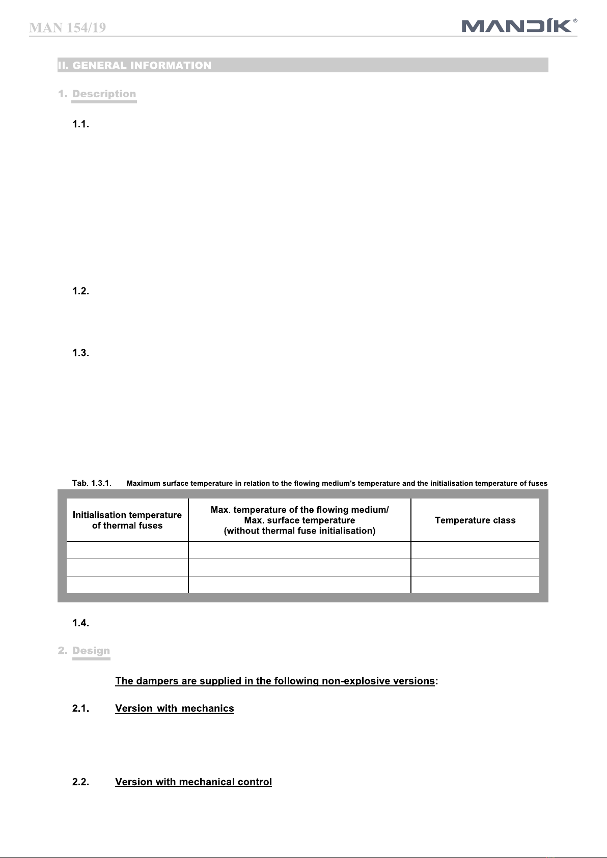
manual and temperature (ZONE 1, 2) .02 II 2G
manual and temperature with limit switch ("CLOSED") (ZONE 1, 2) .12 II 2G
with actuator ExMax-15- BF AC 230V, with thermoelectric activation
ExPro-TT equipment (ZONE 1, 2) .42 II 2G
with actuator ExMax-15- BF AC/DC 24V, with thermoelectric activation
ExPro-TT equipment (ZONE 1, 2) .52 II 2G
Manual and thermal with two limit switches ("OPEN", "CLOSED") (ZONE 1, 2)
.81 II 2G
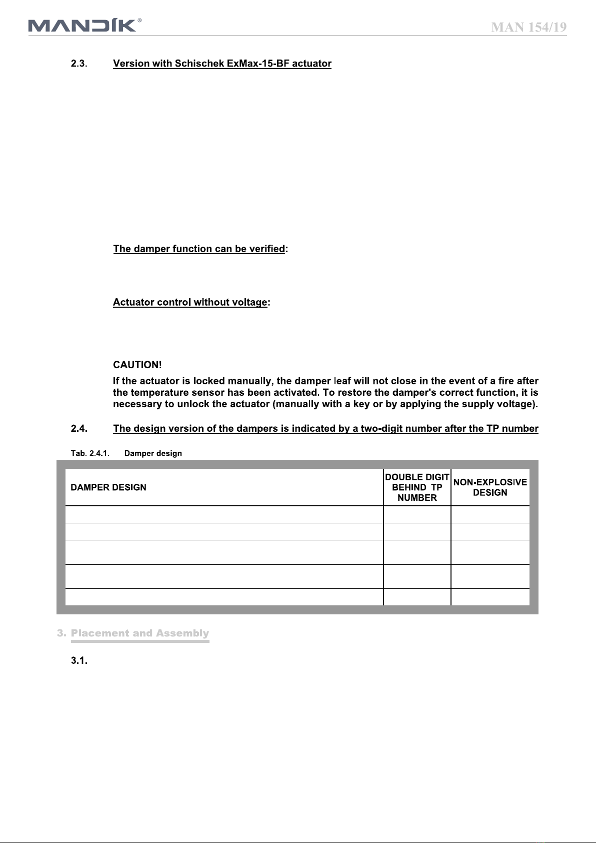
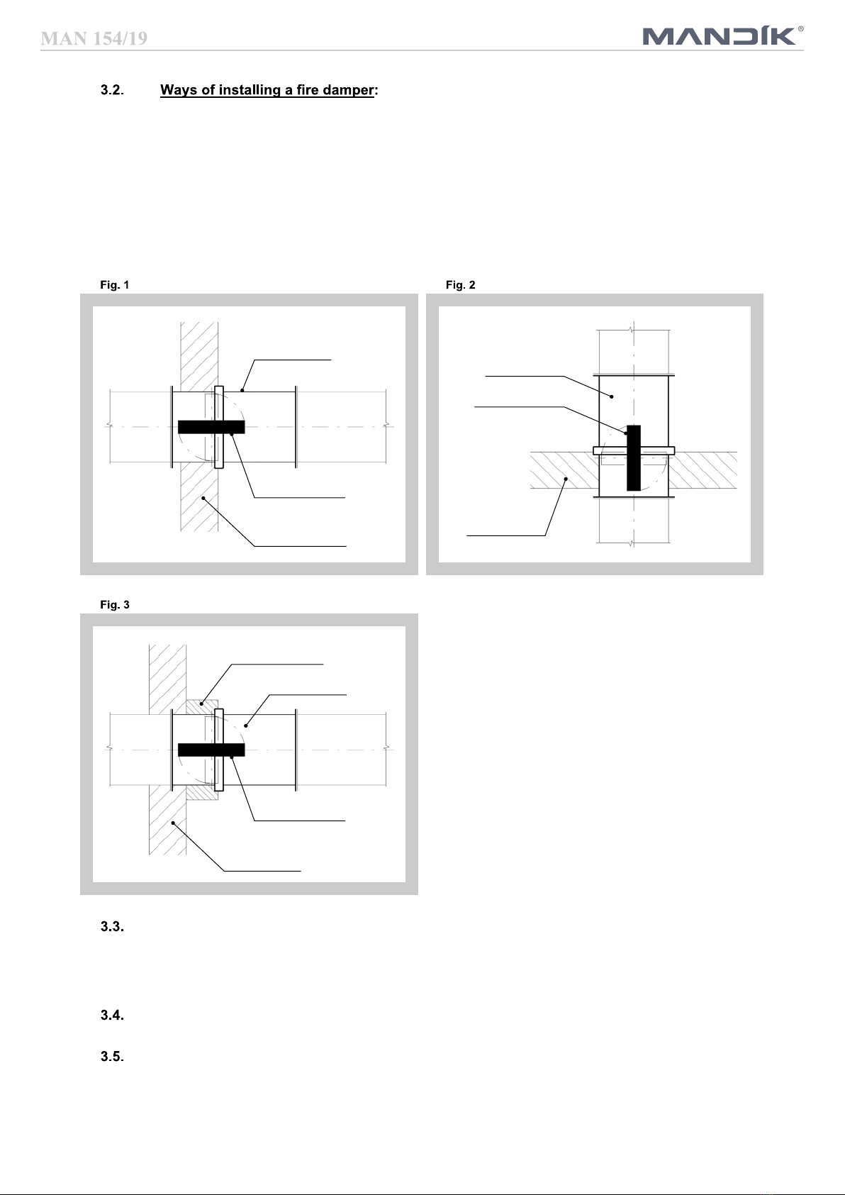
Fire dampers are suitable for installation in vertical and horizontal passages of fire dividing
structures. Penetrations regarding damper installation must be done in such a way that the
transfer of all loads from the fire dividing structures to the damper body is completely excluded.
The adjoining air duct must be suspended or supported in such a way that load transfer from the
adjoining duct to the damper flange is completely ruled out.
To ensure the necessary space for access to the control device, it is recommended that other
objects be at least 350 mm away from the control parts of the damper. At least one inspection
opening must be accessible.
The distance between the fire damper and the structure (wall, ceiling) must be at least 75 mm. If
two or more dampers are to be installed in one fire dividing structure, the distance between
adjacent dampers must be at least 200 mm.
5
The damper must be installed so that the damper leaf (in a closed position) is placed on the edge
with the fire dividing structure or in the fire dividing structure - marked on the damper with the sticker
"EDGE OF THE WALL" (Fig. 1 and 2). If this solution is not possible, the duct between the fire
dividing structure and the damper must be min. to the edge of the wall protected (Fig. 3) as
specified in the standard EN 73 0872. The design must be in accordance with the relevant TPM for
the given type of damper.
Until the wall is plastered it is necessary to protect the control mechanism from damage and
contamination by covering it. The damper body must not be deformed during walling. After
installing the damper, the damper leaf must not scrub on the damper body when opening or closing.
Fire damper
Damper blade
Fire dividing
construction
Fire damper
Damper blade
Fire dividing
construction
Protected duct
Fire damper
Damper blade
Fire dividing
construction
The fire damper can be built into a rigid wall structure made of e.g. ordinary concrete/masonry,
aerated concrete with min. 100mm thickness or into a rigid ceiling structure made of e.g. ordinary
concrete, aerated concrete with min. 110mm thick. Construction openings and penetrations must
be made in accordance with the relevant TPM for the given type of damper.
The fire damper can be built into a light plasterboard wall construction with a min.100 mm thickness.
The fire damper can be installed outside the wall construction. The ducting and the part of the
damper between the wall structure and the damper leaf (marked with the WALL EDGE sticker on
the damper) must be protected by fire insulation. The insulation and penetration must be made in
accordance with the relevant TPM for the damper type.
6
Position:
1 Body – 1 damper 8
Thermo-electrical fuse ExPro-TT
2 Body – 2 damper 9 Inspection hole covering
3 Damper blade 10 Control lever
4 Electrical actuator Schischek ExMax-15BF 11 Pin with lever
5 Mechanical actuator Atex 12 Initiation button
6 Thermal fuse 13 Insulation partition (promat)
7 End switch
7
Position:
1 Body – 1 damper 8
Thermo-electrical fuse ExPro-TT
2 Body – 2 damper 9 Inspection hole covering
3 Damper blade 10 Control lever
4 Electrical actuator Schischek ExMax-15BF 11 Pin with lever
5 Mechanical actuator Atex 12 Initiation button
6 Thermal fuse 13 Insulation partition (promat)
7 End switch
8
Position:
1 Damper casing 7
Thermo-electrical fuse ExPro-TT
2 Damper blade 8 Inspection hole covering
3 Electrical actuator Schischek ExMax-15BF 9 Control lever
4 Mechanical actuator Atex 10 Pin with lever
5 Thermal fuse 11 Initiation button
6 End switch
9
Position:
1 Damper casing 7 Thermo-electrical fuse ExPro-TT
2 Damper blade 8 Inspection hole covering
3 Electrical actuator Schischek ExMax-15BF 9 Control lever
4 Mechanical actuator Atex 10 Pin with lever
5 Thermal fuse 11 Initiation button
6 End switch
10
are manufactured in the size range (A x B): from 150 x 150 mm to 1500 x 800 mm.
: from a diameter of 100 mm to 1000 mm.
FDMB: from 160x160 to 1000x500, or 500x1000 (max. area 0.5 m2, max. side length 1000 mm)
FDMQ: from 150x150 to 1500x800
FDMR: from Ø100 to Ø800 mm
FDMA-PM: Ø900 and Ø1000
Square damper flanges with a width of 30 mm are provided with oval holes in the corners. The
connection dimensions of the round damper flanges are according to ON 120517.
In the case of dampers for SPIRO ducting, the circular dampers are supplied without flanges with
a fitted lip seal.