Komfovent UVA60 H User manual

2021

SIA KOMFOVENT reserves the right to make changes without prior notice
Fire damper UVA60 H / UVA120 H installation manual 21-01
2
EN
CONTENTS
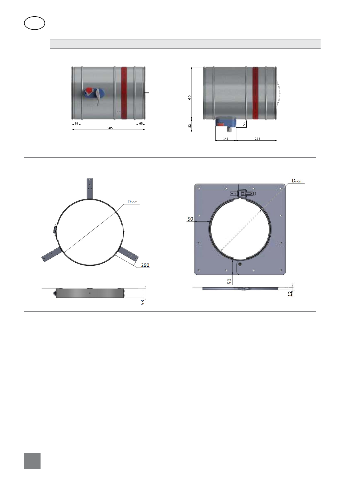
1. FIRE DAMPER DESIGN AND DIMENSIONS...........................................................................................................................3
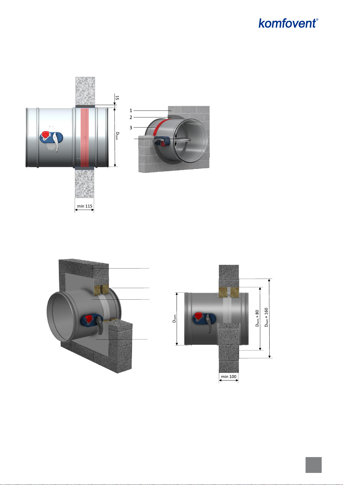
2. INSTALLATION METHODS ..................................................................................................................................................5
2.1. Mortar - based installation in a solid wall ..................................................................................................................5
2.2. “Fire batt” - based installation in a solid wall .............................................................................................................5
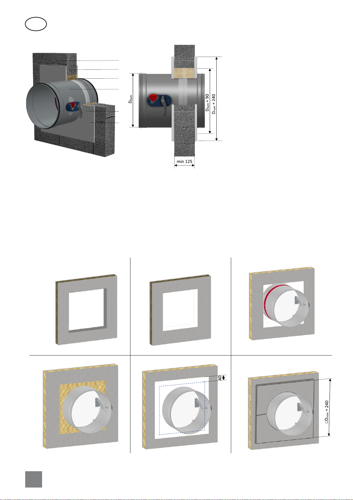
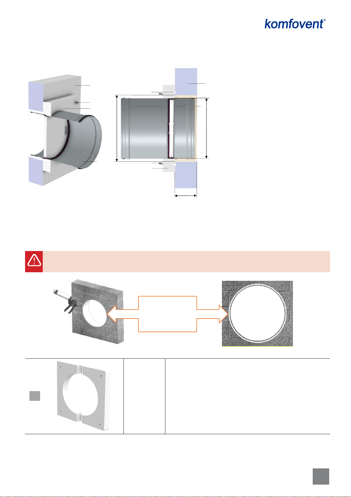
2.3. “Dry montage” installation kit - based installation in a solid wall ...............................................................................7
2.4. Installation in a flexible wall (metal stud drywall) ......................................................................................................9
2.5. Installation in a solid ceiling ....................................................................................................................................10
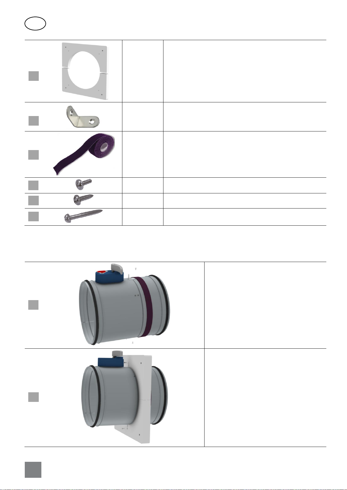
2.6. Application of the montage accessories ..................................................................................................................11
2.7. Installation methods consolidation..........................................................................................................................13
3. SAFETY REQUIREMENTS ..................................................................................................................................................15
4. INSTALLATION STEPS.......................................................................................................................................................16
4.1. Signaling devices (switches) installation instructions ...............................................................................................19
5. PERIODICAL INSPECTIONS ...............................................................................................................................................21

SIA KOMFOVENT reserves the right to make changes without prior notice
Fire damper UVA60 H / UVA120 H installation manual 21-01
3
1. FIRE DAMPER DESIGN AND DIMENSIONS
1 –casing, 2 –blade, 3 –opening device with spring, 4 –intumescent seal, 5 –limit switches (optional),
6 –opening handle, 7 –fuse element, 8 –test button, 9 –marking of blade position
Montage accessories available (for installation guide please refer to page 11)
Steel collar-type montage tool with 3 plates (6 x Ø6 mm holes) –
designed for walls
Steel overlay-type montage tool (12 x Ø5 mm holes) –designed
for ceilings
1
1
2
3
4
5
6
7
8
8
9

SIA KOMFOVENT reserves the right to make changes without prior notice
Fire damper UVA60 H / UVA120 H installation manual 21-01
4
EN
Fire damper UVA-H main sizes for diameter range Ø355 ÷ 560 mm
Montage accessories available (for installation guide please refer to page 12)
Steel collar-type montage tool with 3 plates (6 x Ø6 mm holes) –
designed for walls
Steel overlay-type montage tool (12 x Ø5 mm holes) –designed
for ceilings

SIA KOMFOVENT reserves the right to make changes without prior notice
Fire damper UVA60 H / UVA120 H installation manual 21-01
5
2. INSTALLATION METHODS
2.1.Mortar - based installation in a solid wall
2.2. “Fire batt” - based installation in a solid wall
1. Solid wall (made of concrete, aerated
concrete blocks or masonry, min.
thickness - 115 mm)
2. Plaster or mortar
3. Fire damper UVA 60H / UVA 120H
4. The blade of the damper.
1. Fire damper UVA 120H (Ø100÷315)
2. Solid wall (aerated concrete, bricks,
concrete), minimum 100 mm thick)
3. Mineral wool, min. 100 mm thick, min.
density 140 kg/m³
4. Layer of fire stopping coating with at least B1
fire reaction, min. layer thickness 2 mm.
4
EIS 60 (for size range Ø355 ÷ 560 mm)
EIS 120 (for size range Ø100 ÷ 560 mm)
EIS 60 (for size range Ø100 ÷ 315 mm)
Installation steps:
- prepare square installation opening Dnom + 80 mm
- cover the internal face of the opening with 2 mm fire stopping coating
-use a mounting accessorize to preliminary secure the damper in the
installation opening
- fill the gap between wall and casing of the damper with mineral wool
- apply a fire stopping coating overlapped at wall for 40 mm.
2
1
3
4
Installation steps:
- prepare round installation opening Dnom+30 mm
-use a mounting accessorize to secure the damper in the installation opening
- fill the gap between wall and casing of the damper with plaster or mortar
- let the plaster or mortar dry completely and remove the mounting accessorize.

SIA KOMFOVENT reserves the right to make changes without prior notice
Fire damper UVA60 H / UVA120 H installation manual 21-01
6
EN
1. Wall with Dnom + 90 mm
opening
2. Fire-stopping coating on the internal
face of the opening
3. Fire damper positioning and fixation
4. Mineral wool installation
5. Fire stopping coating
6. Installation of the additional gypsum
boards
1. Fire damper UVA 120H (Ø355÷560)
2. Solid wall (aerated concrete, bricks,
concrete), minimum 125 mm thick)
3. Mineral wool at least 120 mm thick,
min. density 100 kg/m3
4. Layer of fire stopping coating with at
least B1 fire reaction, min. layer thickness
2 mm.
5. Additional two gypsum 12.5 mm thick
boards
6. Rigid wall screws 3.5x50 (interval <200
mm).
EIS 60 (for size range Ø355 ÷ 560 mm)
Installation steps:
- prepare square installation opening Dnom + 90 mm
- cover the internal face of the opening with 2 mm fire stopping coating
- use a mounting accessorize to preliminary secure the damper in the installation opening
- fill the gap between the damper casing and the wall with mineral wool
- apply a fire stopping coating overlapped at wall for 40 mm
- install additional 12.5 mm thick gypsum boards, which size is Dnom + 240 mm, on both sides of the wall.
2
1
3
4
5
6

SIA KOMFOVENT reserves the right to make changes without prior notice
Fire damper UVA60 H / UVA120 H installation manual 21-01
7
2.3. “Dry montage” installation kit - based installation in a solid wall
Fire stopping mastic FireX (or analogue) should be applied directly to the wall around the installation opening within ≈5-10 mm from
it right before the fire damper mounting.
Dry montage kit consists of:
Two С-shape
parts –1 set
Shield flanges made of 40 mm thick Promatect-MT fire-resistant
material
1. Fire damper UVA 120H (Ø100 ÷ 315)
2. Solid wall (aerated concrete blocks, concrete,
masonry in min. thickness 115 mm)
3. Mineral wool, min. density 40 kg/m3
4. Fire stopping mastic FireX (or analogue)
5. Dry montage kit*
6. Mounting anchors (should be selected
accordingly to solid wall type).
* ordered separately
1
Application of the
Fire stopping mastic
around the
installation opening
EIS 60 (for size range Ø100 ÷ 315 mm)
2
2
3
5
1
5
6
6
4
Installation steps:
- prepare round installation opening Dnom + 30 mm
- apply fire stopping coating around the opening on the outer side of the wall surface (see picture below)
- install the damper into the opening, using appropriate fasteners
- fill the gap between the damper casing and the wall with mineral wool.
Dnom
Dnom + 30
min 115

SIA KOMFOVENT reserves the right to make changes without prior notice
Fire damper UVA60 H / UVA120 H installation manual 21-01
8
EN
Two С-shape
parts –1 set
Shield flanges made of 20 mm thick Promatect-MT fire-resistant
material
2 pcs.
Metal corner for joining shield flanges to the casing of the damper
Strip cut in
size
Promaseal –GT intumescent tape for filling the gap between
shield flange and casing
2 pcs.
DIN 967 M4x8 screw to install metal corners on the casing
2 pcs.
ISO 7049 3.5x13 screw to attach shield flange to the metal corner
4 pcs.
Construction screw 4.0x30 for joining together shield flange parts
“Dry montage” set’ assembling steps
It is easier to preinstall Dry montage kit on the damper casing first and then install the damper into the opening:
Take two metal corners [3] and attach them to
the casing of the damper by using two DIN 967
screws [5] and existing threaded holes, covered
with the red protecting tape.
Glue Promaseal-GT tape [4] to the casing on the
damper using previously attached metal corners
as a guide point.
Using two ISO 7049 screws [6], join shield flanges
[2] to the previously installed metal corners [3].
2
1
2
3
4
5
6
7

SIA KOMFOVENT reserves the right to make changes without prior notice
Fire damper UVA60 H / UVA120 H installation manual 21-01
9
Using four ISO 7049 screws [7], join shield flanges
[2] to the previously installed shield flanges [1].
The junctions of the two flanges should not
overlap, but are at 90°.
Pre –installed Dry montage kit on the damper
casing.
2.4. Installation in a flexible wall (metal stud drywall)
Internal face of the square opening must be also coated with 2 mm thick fire-resistant coating with min. fire
resistant capacity EI 120 for all installations in a flexible wall
1. Fire damper UVA 120H (Ø100 ÷ 315)
2. Flexible wall (metal stud drywall, min. 100 mm
thick)
3. Mineral wool, min. 100 mm thick, min. density
140 kg/m3
4. Layer of fire stopping coating with at least B1
fire resistance
1
.
F
i
r
e
d
a
m
p
e
r
U
V
A
1
2
0
H
3
4
EIS 60 (for size range Ø100 ÷ 315 mm)
Dnom + 80
Dnom
1
1
2
2
3
3
4
4
Installation steps:
- prepare square installation opening Dnom+80
mm
-use a mounting accessorize to secure the
damper in the installation opening
- fill the gap between wall and casing of the
damper with mineral wool and remove the
mounting accessorize
- cover the mineral wool (overlapped the wall)
with stopping mastic.
Dnom + 160
min 100

SIA KOMFOVENT reserves the right to make changes without prior notice
Fire damper UVA60 H / UVA120 H installation manual 21-01
10
EN
2.5. Installation in a solid ceiling
Installations with main mechanism located above or below the ceiling panel are acceptable.
1. Fire damper UVA-120H (Ø355 ÷ 560)
2. Flexible metal stud drywall, min. 125 mm
thick
3. Mineral wool slabs 120 mm thick, min.
density 100 kg/m3
4. Layer of fire stopping coating with at least
B1 fire reaction, min. layer thickness 2 mm.
5. Additional two gypsum 12.5 mm thick
boards.
1. Solid ceiling (monolith or hollow
concrete, reinforced concrete min. 150 mm
thick panels, min. density 2200 kg/m³)
2. Plaster or mortar
3. Fire damper UVA 120H
EIS 60 (for size range Ø315 ÷ 560 mm)
1
3
5
Dnom + 90
Dnom
min 125
2
3
5
4
Installation steps:
- prepare square installation opening Dnom + 90 mm
-use a mounting accessorize to secure the damper in the installation opening
- fill the gap between wall and casing of the damper with mineral wool and remove the mounting accessorize
- cover the mineral wool (overlapped the wall) with stopping mastic
- install additional 12.5 mm thick gypsum boards, which size is Dnom + 240 mm, on both sides of the wall.
EIS 120 (for size range Ø100 ÷ 560 mm)
min 150
15
1
2
3
Installation steps:
- prepare round installation opening Dnom + 30 mm
-use a mounting accessorize to secure the damper in the installation
opening
- fill the gap between wall and casing of the damper with plaster or
mortar
- let the plaster or mortar dry completely and remove the mounting
accessorize.

SIA KOMFOVENT reserves the right to make changes without prior notice
Fire damper UVA60 H / UVA120 H installation manual 21-01
11
2.6. Application of the montage accessories
Mounting accessories are designed to facilitate the installation process of the fire damper by securing it in the installation
opening during the mounting process.
US-type mounting accessories is used for UVA-H damper wall mounting, but UL-type –for ceiling mounting.
US - d mounting accessorize
UL - d mounting accessorize
For each fire damper diameter (Ø100, Ø125, Ø160, Ø200, Ø250, Ø315, Ø355, Ø400, Ø450, Ø500, Ø560) relevant size of
mounting accessorize (US or UL depending on installation in the wall or in the ceiling) is required. Still the mounting accessorize
is re-usable, it is possible not to order the mounting accessorize for each fire damper should be installed on the site individually.
1. The mounting accessorize should be
established on the damper casing before
starting the installation.
2. For the damper diameter range Ø
100÷315 the mounting collar is established right
behind the main mechanism or the actuator, for
size range Ø 355÷560 the distance between the
red tape and the collar should be around 50
mm. The specified position is appropriate –the
major installation requirement the red tape is
supposed to be located in the supporting
construction.
Positioning of
the collar for
size range
Ø100÷315 mm
Positioning of
the collar for
size range
Ø355÷560 mm
≈50

SIA KOMFOVENT reserves the right to make changes without prior notice
Fire damper UVA60 H / UVA120 H installation manual 21-01
12
EN
3. The appropriate fastenings should be
used to establish the damper onto the
supporting construction. For reference in the
hole sizes and location please use drawing of
the relevant type of the mounting collar.
For ceiling installation please be sure the collar is
places under the ceiling panel to ensure that filling
the gap with mortar is possible.
4. When the damper is affixed to the
supporting construction, finish the mounting
process in acc. with the installation instructions.
5. After finishing the installation process
the mounting collar can be removed and re-
used for the next fire damper installation.
Application of the mounting collar types depending on the fire damper diameter and supporting construction (wall, ceiling):
Montage collar US-d for d = [100 ÷ 315] mm
6 x Ø6 mm mounting holes
For vertical fire damper installation in the wall
Montage collar US-d for d = [355 ÷ 560] mm
6 x Ø6 mm mounting holes
For vertical fire damper installation in the wall
Filling
material
Supporting
construction
Mounting
collar

SIA KOMFOVENT reserves the right to make changes without prior notice
Fire damper UVA60 H / UVA120 H installation manual 21-01
13
Montage collar UL-d for d = [100 ÷ 560] mm
12 x Ø5 mm mounting holes
For horizontal fire damper installation in the
ceiling
2.7. Installation methods consolidation
Summary of the described installation methods:
Supporting
construction
Construction details
Construction
details
Size and type
of the damper
Installation
details*
Class of
performance
Solid wall
Solid homogeneous wall
(aerated concrete blocks,
masonry, concrete blocks with
min. density 650 kg/m3), min.
thickness 115 mm
Mortar filling
UVA-120H
100 ÷ 560 mm
1, 3, 4, 5
EI 120 (vei↔o) S
300 Pa
UVA-60H
355 ÷ 560 mm
EI 60 (vei↔o) S
300 Pa
Solid homogeneous wall
(aerated concrete blocks,
masonry, concrete blocks with
min. density 650 kg/m3), min.
thickness 100 mm
Mineral wool min.
140 kg/m3 with fire
resistant coating
UVA-120H
100 ÷ 315 mm
1, 3, 4, 5
EI 60 (vei↔o) S
300 Pa
Solid homogeneous wall
(aerated concrete blocks,
masonry, concrete blocks with
min. density 650 kg/m3), min.
thickness 125 mm
Mineral wool min.
100 kg/m3 with fire
resistant coating
and additional
plasterboard pads
UVA-120H
355 ÷ 560 mm
1, 3, 4, 5
EI 60 (vei↔o) S
300 Pa
Solid homogeneous wall
(aerated concrete blocks,
masonry, concrete blocks with
min. density 650 kg/m3), min.
thickness 115 mm
Calcium silicate
“Dry montage” kit
UVA-120H
100 ÷ 315 mm
1, 3, 4, 5
EI 60 (vei↔o) S
300 Pa
Flexible wall
Metal stud gypsum
plasterboard F
(EN 520) ≥ 100 mm
Mineral wool min.
140 kg/m3 with fire
resistant coating
UVA-120H
100 ÷ 315 mm
1, 3, 4, 5
EI 60 (vei↔o) S
300 Pa

SIA KOMFOVENT reserves the right to make changes without prior notice
Fire damper UVA60 H / UVA120 H installation manual 21-01
14
EN
Metal stud gypsum
plasterboard F
(EN 520) ≥ 125 mm
Mineral wool min.
100 kg/m3 with fire
resistant coating
and additional
plasterboard pads
UVA-120H
355 ÷ 560 mm
1, 3, 4, 5
EI 60 (vei↔o) S
300 Pa
Ceiling slab
Monolithic or hollow core slab
≥ 150 mm
Mortar filling
UVA-120H
100 ÷ 560 mm
2, 4, 5
EI 120 (hoi↔o) S
300 Pa
* 1-positioning of the damper: vertical;
2 - positioning of the damper: horizontal;
3 - axis position: horizontal;
4 –min. distance between casings: 200 mm;
5 –min. distance to load-bearing structural elements: 75 mm

SIA KOMFOVENT reserves the right to make changes without prior notice
Fire damper UVA60 H / UVA120 H installation manual 21-01
15
3. SAFETY REQUIREMENTS
Protective gloves must
be worn
Protective gloves protect
hands against abrasion,
oily environment, sharp
metal parts and contact
with hot surfaces.
Protective industrial
helmet must be worn
Industrial helmets protect
the head against impact
from objects falling from
above, by resisting and
deflecting blows to the
head.
Protective boots must
be worn
Protective boots protect
the foot from falling
objects or compression
and prevent slipping on a
slippery floor.
Incorrect use might
cause dangerous
situations
The local regulations for health and safety at work and general safety regulations to be applied.
Personal protective equipment must be worn for such types of work: fire damper electrical installation, fire damper
mechanical connection to the air duct system (ductwork) and any type of service or maintenance works.
It is important to correctly use the fire damper in prescribed way only:
•Fire damper is permitted to use in exhaust or supply air systems.
•Not allowed to operate the fire damper if it do not comply with manufacturer’s installation requirements specified in this
instruction.
•Any changes or modifications of the fire damper are strictly prohibited, except for using manufacturer’s provided replacement
parts.
•Qualified staff only are allowed to replace parts or service the fire damper.

SIA KOMFOVENT reserves the right to make changes without prior notice
Fire damper UVA60 H / UVA120 H installation manual 21-01
16
EN
4. INSTALLATION STEPS
Before starting installation process any fire damper shall be inspected for damages by responsible person!
The installation process must include the following steps:
1. Check if the blade is closing and opening without additional resistance by
pressing “Push’ button several times. If sticking occurs, lubricate rotation points
as shown below using a suitable amount of lubricating agent:
2. Please consider that fire dampers starting with Ø315 mm have exposition of the blade into the duct within a certain
distance:
Ø, mm
La, mm
315
28
355
34
400
56
450
81
500
106
560
136
3. Close the blade of a fire damper. If a fire damper has been installed with an open blade, this may cause incomplete
closing of the blade or even damage! Blade position can be easily controlled also after installation by referring to marks
located on the casing of locking mechanism:
Blade open
Blade closed
4. Cover the main mechanism (if delivered uncovered) in the process of damper installation with plastic film or another
material to protect it against clogging with construction dust and materials.
Dnom
La
The fuse element is single-use
only and should be replaced
after activation.
The fuse element can be easily
accessible by screwing out PUSH
button screw and pulling out
the thermal release mechanism.
In case the fuse element is
melted it can be simply replaced
with a new one.

SIA KOMFOVENT reserves the right to make changes without prior notice
Fire damper UVA60 H / UVA120 H installation manual 21-01
17
5. Prepare installation opening in the wall (solid or flexible) or in the ceiling in accordance with the projected type of the
installation.
It is highly recommended to install the fire dampers in a way that completely prevents excess load on the dampers and transfer any load
from ducts or supporting constructions!
6. The distance between multiple fire dampers installed close to each other shall not exceed 200 mm, as well as damper
must not be installed closer than 75 mm to the walls, ceiling or other partitions, but it is recommended to leave the access
space to main mechanism at least 300 mm. The axle of the damper blade may be located only horizontally!
7. Attach the fire damper to the supporting construction using suitable montage kit and fasteners. It is possible to re-use
these kits again.
Brackets are used for tight holding of fire
damper when wall mounting brackets
cannot be used.
Steel overlay-type montage tool can be
used for positioning the fire damper in the
cut-out and holding fire resistant
insulation on the ceiling.
Steel collar-type montage holders can be
used to align the fire damper in the cut-
out by tightening it on the fire damper’s
casing and installing metal plates on a
wall.
Note: for installation of a damper into a wall axle of the blade should be positioned horizontally only! Blade of a damper always has to be
placed INSIDE the supporting construction. Main mechanism can be used as a guide to find right damper’s position:

SIA KOMFOVENT reserves the right to make changes without prior notice
Fire damper UVA60 H / UVA120 H installation manual 21-01
18
EN
It is extremely important that the blade is positioned into the supporting construction, if possible closer to its
center. Red duct tape can be used as a guide to identify fire damper’s blade position.
It is also recommended to provide approx. 8 to 10 mm distance between supporting
construction (wall or ceiling) edge and main mechanism of the fire damper.
It is important to select only appropriate fastening for fire damper supporting based on its weight:
Ø, mm
m, kg (UVA-60H)
m, kg (UVA-120H)
100
1.5
1.5
120
1.7
1.7
160
2.1
2.1
200
2.5
2.5
250
3.1
3.1
315
3.9
3.9
355
7.9
9.8
400
9.0
11.4
450
10.4
13.4
500
11.9
15.6
560
13.7
18.5
Please be advised, that after installation of the damper periodical inspections will be held in accordance with p. 4 and it is necessary to ensure access
to the main mechanism of a fire damper.
8. Fill in the gap between the casing and supporting construction with prescribed type of the filler and if required let the
filler dry out completely before removing montage kit (follow the filler producer’s instructions).
9. Visually check that fire damper is securely installed into the supporting construction, check if the fuse element and
levers system are undamaged and check if the blade is closing and opening properly by pressing “Push’ button several times.
The blade must be fully closed and no seizing should be observed.
10. When fire damper is fully installed and verified, make sure it is left in its normal working position with blade OPEN.
11. Please consider that all EU working safety and Fire safety standards must be observed during the installation process.
12. End position microswitches is an additional option that can be used to identify the blades position from a distance. For
each position of the blade (OPEN / CLOSE) one end switch is needed. Meaning in total it will be two end position switches for
one fire damper. It is easy to mount end positions switches on fire dampers with plastic actuation mechanism –only one
additional plastic part must be installed. This plastic part comes as a set with the switches.
≈ 8 to 10 mm

SIA KOMFOVENT reserves the right to make changes without prior notice
Fire damper UVA60 H / UVA120 H installation manual 21-01
19
4.1.Signaling devices (switches) installation instructions
If fire damper is additionally completed by one or two signaling devices (microswitches) and switch cam, simple installation
of the parts is required:
Switch cam –1 pc. Microswitch –1 or 2 pcs.
Installation steps:
1. Unscrew damper’s handle holding screw DIN 912,
then remove handle and cap:
3. Place
switch cam
and handle
back and
screw in
DIN 912
screw:
2. Place switch cam to
the axis and one or
two microswitches
to the indicated
positions. Make sure
that the cam ledge
pushes the
microswithes’
metal plate.
4. Connect microswitches to designed way. Each microswitch
has NC (normally closed), NO (normally open) and C (common)
poles. Connection scheme using signaling device:
Each microswitch has NC (normally closed), NO (normally open)
and C (common) poles. Connection scheme using signaling device
is shown below:
ACTION SHOULD BE TAKEN IF THE CAM DOESN’T PRESS THE
METAL PLATE:
V
V
Using an appropriate tool (e.g. pliers), GENTLY fold the metal
plate as shown:
Avoid to fold the plate too hard so it can be broken!

SIA KOMFOVENT reserves the right to make changes without prior notice
Fire damper UVA60 H / UVA120 H installation manual 21-01
20
EN
SELF-TEST IS REQUIRED AFTER THE COMPLETION OF THE FIRE DAMPER INSTALLATION!
IF ANY OF THE FOLLOWING ISSUES OBSERVED AFTER THE FIRE DAMPER INSTALLATION, IT IS STRICTLY PROHIBITED TO
ACCEPT IT INTO OPERATION:
•INSPECTION HATCH (WHERE INCORPORATED INTO THE CASING OF THE DAMPER OR INTO THE CONNECTING DUCT) IS
INACCESSIBLE;
•BLADE OF THE FIRE DAMPER IS BLOCKED IN OPEN POSITION;
•CASING OF THE FIRE DAMPER HAD BEEN DAMAGED DURING INSTALLATION PROCESS;
•THE FIRE DAMPER IS FITTED WITHOUT OBSERVING THE REQUIREMENTS OF THIS INSTRUCTION;
•FASTENERS USED DURING INSTALLATION PROCESS PREVENT CLOSING OF THE FIRE DAMPER BLADE;
•GAPS BETWEEN CASING OF THE FIRE DAMPER AND THE SUPPORTING CONSTRUCTION REMAIN UNFILLED;
•THE DAMPER IS INSTALLED REMOTELY FROM THE WALL OR CEILING;
•CONSTRUCTION WASTE OR DUST LEFT ON THE SURFACES OF THE DAMPER;
•ACTUATOR IS DISCONNECTED OR MOUNTED LOOSE ON SHAFT;
•WIRES RUN THROUGH THE FIRE DAMPER.
This manual suits for next models
1
Table of contents
Other Komfovent Fire And Smoke Damper manuals