Ingersoll-Rand ARO SB30 Series User manual

INGERSOLL RAND COMPANY INC
209 NORTH MAIN STREET – BRYAN, OHIO 43506
(800) 495-0276 FAX (800) 892-6276 © 2023 CCN 99828618
arozone.com
OPERATOR’S MANUAL SB30X-XXX-X
INCLUDING: OPERATION, INSTALLATION AND MAINTENANCE RELEASED: 2-18-00
REVISED: 4-21-23
(REV: K)
3" SHOCK BLOCKER®
METALLIC PULSATION DAMPENER
READ THIS MANUAL CAREFULLY BEFORE INSTALLING,
OPERATING OR SERVICING THIS EQUIPMENT.
It is the responsibility of the employer to place this information in the hands of the operator. Keep for future reference.
SERVICE KITS
Refer to the Model Description Chart to match the pump ma-
terial options.
637330-3X for repair of the diaphragms and “O” rings (see
page 5).
PUMP DATA
Models........................see Model Description
Chart for “-XXX-X”
Pulsation Dampener Type ....Metallic
Material.......................see Model Description Chart
Weight
SB30X-XAX-X ...............41 lbs (18.6 kgs)
SB30X-XCX-X ...............94 lbs (42.6 kgs)
SB30X-XSX-X ...............96 lbs (43.5 kgs)
SB30X-FSX-X ...............106.5lbs (48.3kgs)
Material Inlet / Outlet
SB30X-AXX-X ...............3 - 8 NPTF - 1
SB30X-BXX-X ...............Rp 3 (3 - 11 BSP parallel)
SB30X-FSX-X ...............3” Hybrid ANSI / DIN /
JIS RF Flange
Air Inlet (female) ..............3/4 - 14 NPT
Maximum Air Inlet Pressure ..120 psig (8.3 bar)
Maximum Material
Inlet Pressure .................120 psig (8.3 bar)
Maximum Temperature Limits (diaphragm / seal material)
E.P.R. / EPDM ...................-60° to 280° F (-51° to 138° C)
Nitrile .........................10° to 180° F (-12° to 82° C)
Santoprene® ...................-40° to 225° F (-40° to 107° C)
PTFE®..........................40° to 225° F (4° to 107° C)
Viton® .........................-40° to 350° F (-40° to 177° C)
Maximum Fluid Volume ......367 in.³ (6.01 lit.)
Dimensional Data.............see page 8
NOTICE: All possible options are shown in the chart, however, certain
combinations may not be recommended, consult a representative or
the factory if you have questions concerning availability.
Thread option models
Flange option models
Figure 1

Page 2 of 8 SB30X-XXX-X (en)
MODEL DESCRIPTION CHART
SB30X X
Air Section Material
A -
XXX
Aluminum
Fluid Connection
A -3- 8 NPTF - 1
B - Rp 3 (3 - 11 BSP, parallel)
-
F - 3” Hybrid ANSI / DIN /JIS RF Flange
Hardware Material
Fluid Cap Material
A - Aluminum
C - Cast Iron
S - Stainless Steel
Diaphragm Material
A -Santoprene
P -Carbon Steel
G - Nitrile
L - Long Life PTFE/ Santoprene
T - PTFE / Santoprene
V -Viton
S - Stainless Steel
SB30X - XXX - X
Diaphragm
FLUID SECTION SERVICE KIT SELECTION
EXAMPLE: MODEL # SB30A-BAP-G
Fluid Section Service Kit # 637330-3G
637330 - 3 X
NOTICE: All possible options are shown in the chart, however, certain combinations may not be recommended.
Consult a representative or the factory if you have questions concerning availability.
S - Stainless Steel

SB30X-XXX-X (en) Page 3 of 8
OPERATING AND SAFETY PRECAUTIONS
READ, UNDERSTAND AND FOLLOW THIS INFORMATION TO AVOID INJURY AND PROPERTY DAMAGE.
WARNING
EXPLOSION HAZARD. Do not exceed maxi-
mum uid inlet pressure of 120 PSI (8.3 bar). Operat-
ing at higher pressure can cause explosion, resulting in
property damage or severe injury.
WARNING
USE ONLY WITH COMPRESSED AIR. Do not
use bottled gas products to run the pulsation damp-
ener. Unregulated high pressure bottled gas has the
potential for over-pressurization. Certain gasses, such as
Nitrogen, can cause unpredictable results. The pressure
source MUST BE REGULATED.
WARNING
CHEMICAL COMPATIBILITY HAZARD. Do not
use with certain uids. Incompatible uids may attack
and weaken the housing, causing rupture or explosion,
which can result in property damage or severe injury. See
manufacturer’s information on uid compatibility.
WARNING
DISASSEMBLY HAZARD. Do not disassemble
this unit when it is under pressure. Relieve all mate-
rial pressure in the pumping system before attempting
service or disassembly. Disconnect air lines and carefully
bleed any pressure o the system. Be certain the system
is not maintaining pressure due to a material restriction
in the hose, line, dispensing device or the spray or extru-
sion tip. Failure to relieve pressure, both upstream and
downstream, may result in an injury upon disassembly.
CAUTION
AIR MUST BE SUPPLIED TO THE SHOCK
BLOCKER BEFORE APPLYING FLUID PRESSURE. Fail-
ure to pressurize with air first can damage the dia-
phragm.
CAUTION
ALWAYS RELIEVE THE FLUID PRESSURE
BEFORE REMOVING THE AIR PRESSURE. Failure to re-
lieve uid pressure can damage the diaphragm.
CAUTION
NOT FOR STRUCTURAL SUPPORT. Do not use
this product to support other system components or
use as a step. Improper support can result in fracture of
the housing, causing damage. Plumbing must be sup-
ported to prevent stresses upon it.
NOTICE
Replacement warning labels are available upon
request: “Static Spark & Diaphragm Rupture”pn \ 94080.
WARNING
= Hazards or unsafe practices which
could result in severe personal injury,
death or substantial property damage.
CAUTION
= Hazards or unsafe practices which
could result in minor personal injury,
product or property damage.
NOTICE
= Important installation, operation or
maintenance information.
OPERATING INSTRUCTIONS
WARNING
HEED WARNINGS AS SHOWN IN “OPERATING
AND SAFETY PRECAUTIONS” ABOVE.
AIR REQUIREMENTS
ySupply the unit with clean, dry air.
yA filter capable of filtering out particles larger than 50
microns should be used on the air supply.
INSTALLATION INSTRUCTIONS
yPosition the shock blocker pulsation dampener as close to the
pump discharge as possible (as shown in gure 2).
CAUTION
SUPPORT THE PIPE IMMEDIATELY DOWN-
STREAM FROM THE SHOCK BLOCKER. Support is re-
quired to eliminate forces and moments from the shock
blocker anges and pump manifold. Cantilever support
is suggested immediately downstream from the shock
blocker.
yUse a tee connector after the F-R-L on the pump air sup-
ply line and connect the line to the shock blocker’s valve
body (1/4” ID hose is sufficient). When the air supply to
the pump is shut down, the air to the shock blocker will
be shut down as well.
Filter
Regulator
Lubricator Valve
Check
Valve
Valve
Back
Pressure
Gauge
(optional)
Discharge
Suction
Support required.
(see “Installation Instructions”)
Figure 2
yViton® are registered trademarks of the Chemours Company ySantoprene® is a registered trademark of Celanese y
yLubriplate® is a registered trademark of Lubriplate Lubricants Company yARO® and Shock Blocker® are registered trademarks of Ingersoll-Rand Company y

Page 4 of 8 SB30X-XXX-X (en)
GENERAL DESCRIPTION
The ARO® shock blocker pulsation dampener is designed
to work with 1:1 ratio pumps having an outlet pressure not
exceeding 120 psi (8.3 bar). The shock blocker will eectively
reduce material pressure variations, surges and shock to pip-
ing and delivery in uid systems during pump reversal. It can
significantly contribute to pulse reduction in low pressure
spray applications.
Accurate selection of wetted material will assure longest ser-
vice life and minimize down time. Several material options
are available for the body and diaphragm materials. Fluid
section materials available include: aluminum, cast iron and
stainless steel. For specific fluid compatibility, consult the
chemical manufacturer.
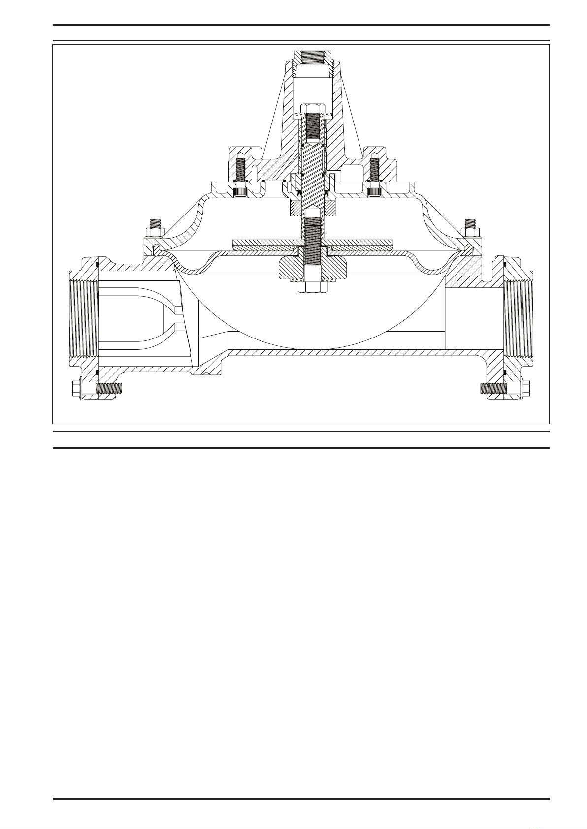
The shock blocker uses a single air pressurized, flexible di-
aphragm working against the fluid line pressure. Several
diaphragm material options are available to allow custom
matching to the uid material for best compatibility (refer to
the model description chart).
Shock blocker units can also be added in series to provide
additional dampening on the material.
Pressure relief through the exhaust port is a normal compen-
sating function of the control valve in the shock blocker. It
will automatically adjust itself to the required operating pres-
sure once the material pressure has been applied. The pres-
sure supplied to the shock blocker needs to be equal to the
material pressure to provide the proper dampening eect.
AIR AND LUBE REQUIREMENTS
WARNING
EXCESSIVE AIR PRESSURE. Can cause pulsa-
tion dampener damage, personal injury or property
damage.
yA filter capable of filtering out particles larger than 50
microns should be used on the air supply. There is no lu-
brication required other than the“O”ring lubricant which
is applied during assembly or repair.
yIf lubricated air is present, make sure that it is compatible
with the“O” rings and seals in the air motor section of the
pump.
OPERATION
CAUTION
DO NOT EXCEED 120 PSI (8.3 BAR). Operating
at higher pressure can cause explosion, resulting in prop-
erty damage or severe injury.
yPressure relief through the exhaust port is a normal
compensating function of the control valve in the shock
blocker. It will automatically adjust itself to the required
operating pressure once the material pressure has been
applied.
yOperate the system for a few minutes to equalize air and
uid chambers of the pulsation dampener.
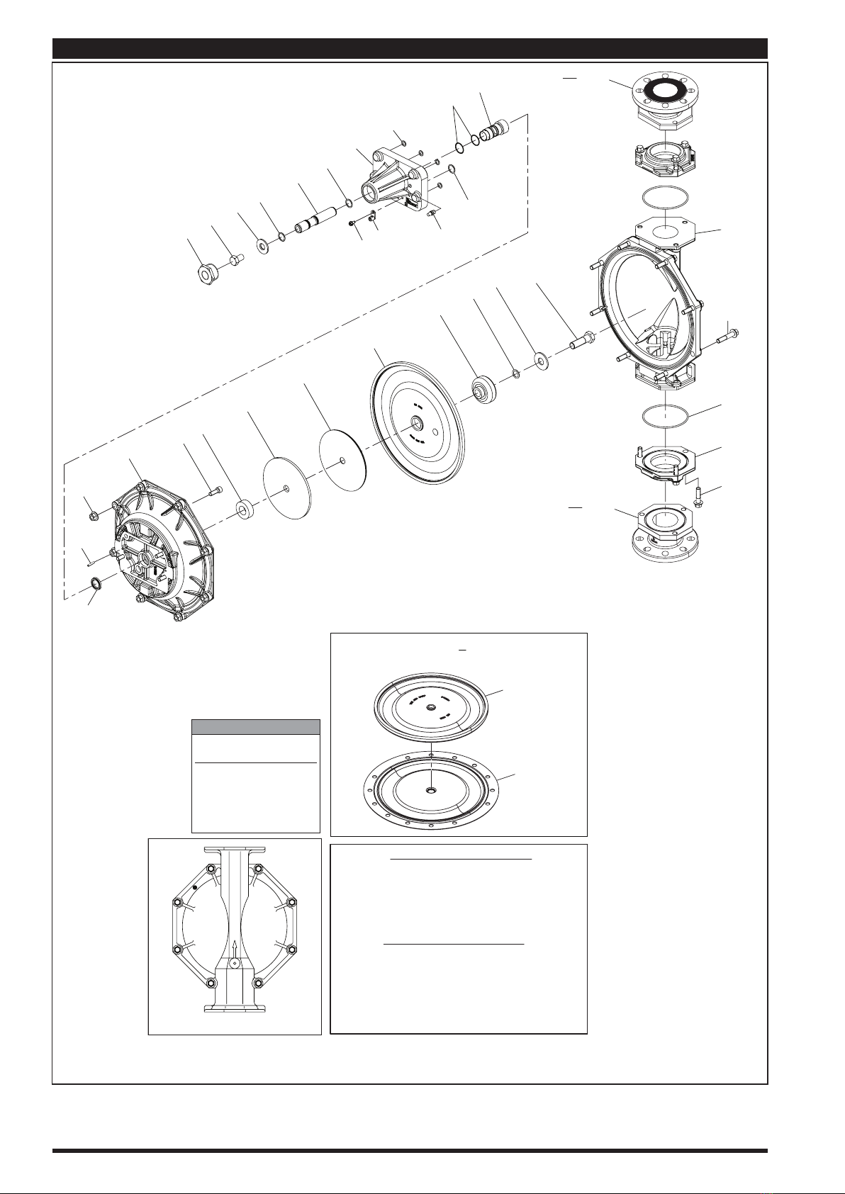
PARTS AND SERVICE KITS
Refer to the part views and descriptions as provided on pag-
es 5 and 6 for parts identication and Service Kit information.
yCertain ARO “Smart Parts” are indicated which should be
available for fast repair and reduction of down time.
MAINTENANCE
yProvide a clean work surface to protect sensitive internal
moving parts from contamination from dirt and foreign
matter during service disassembly and reassembly.
yKeep good records of service activity and include pump
in preventive maintenance program.
yBefore disassembling, empty captured material in the
uid cap by tipping the pulsation dampener on end.
FLUID SECTION DISASSEMBLY
1. Remove (107) reducing bushing.
2. Remove six (26) screws, releasing two (4) anges and (11)
“O”rings.
3. Remove eight (27) screws and (29) nuts, releasing (15)
uid cap.
4. Secure (14) screw in a vise, with (101) air valve body up-
ward.
5. Using a 15/16” socket on (186) screw, unthread and re-
move (186) screw and (9) washer.
6. Remove (68) air cap from (7) diaphragm and compo-
nents.
7. Remove (14) screw from the vise. Unthread and remove
(1) rod, releasing (2) stopper, (5) back-up washer, (7) or (7
and 8) diaphragms, (6) washer and (9) washer from (14)
screw.
8. Remove four (131) screws, releasing (101) air valve body
from the (68) air cap.
9. Remove (144)“U” cup from (68) air cap.
10. Remove (103) sleeve from (101) air valve body.
FLUID SECTION REASSEMBLY
yClean and inspect all parts. Replace worn or damaged
parts with new parts as required. Lubricate all replace-
ment parts and metallic moving parts with Lubriplate®
FML-2 grease upon reassembly.
1. Grease and assemble two (172)“O” rings to (103) sleeve.
2. Assemble (103) sleeve into the (101) air valve body.
3. Grease and assemble (70 and 173) “O” rings to (101) air
valve body.
4. Grease and assemble (144)“U”cup into (68) air cap.
5. Assemble (101) air valve body to (68) air cap.
6. Assemble four (131) screws, securing (68) air cap. NOTE:
Tighten (131) screws to 20 - 30 ft lbs (27.1 - 40.7 Nm).
7. Assemble (9) washer, (6) washer, (7) or (7 and 8) dia-
phragms, (5) back-up washer and (2) stopper to (14)
screw. NOTE: For models with PTFE diaphragms: Item (8)
Santoprene diaphragm is installed with the side marked
“AIR SIDE” towards the pump center body. Install the
PTFE diaphragm (7) with the side marked “FLUID SIDE”
towards the (15) uid cap.
8. Assemble (1) rod to (14) screw.
9. Grease and assemble two (173)“O” rings to (1) rod.
10. Place this assembly into (68) air cap.
11. Assemble (9) washer and (186) screw into (101) air valve
body and thread into (1) rod. Clamp (14) screw in a vise,
with (186) screw upward, and tighten (186) screw to 65 -
70 ft lbs (88.1 - 94.9 Nm).
12. Remove assembly from the vise and assemble to (15)
uid cap, securing with eight (27) screws and (29) nuts.
NOTE: Tighten (27) screws to 60 - 70 ft lbs (81.3 - 94.9
Nm).
13. Grease and assemble two (11)“O” rings to two (4) anges.
14. Assemble two (4) anges to (15) uid cap, securing with
four (26) screws. NOTE: Tighten (26) screws to 60 - 70 ft
lbs (81.3 - 94.9 Nm).
15. Apply Lubriplate FML-2 grease to threads of (101) air
valve body. Apply PTFE tape to threads of (107) reducing
bushing and assemble to (101) air valve body.

SB30X-XXX-X (en) Page 5 of 8
MATERIAL CODE
[A] = Aluminum
[B] = Nitrile
[Br] = Brass
[Bz] = Bronze
[C] = Carbon Steel
[CI] = Cast Iron
[Co] = Copper
[D] = Acetal
[E] = E.P.R.
[I] = Iron
[L] = Long Life PTFE
[Sp] = Santoprene
[SS] = Stainless Steel
[T] = PTFE
[V] = Viton
PARTS LIST / SB30X-XXX-X
Indicates parts included in 637330-3X service kit. Service kit also includes 94276 Lubriplate® FML-2 grease packet.
DIAPHRAGM OPTIONS SB30X-XXX-X
SB30X-XXX-A SB30X-XXX-G SB30X-XXX-T SB30X-XXX-V SB30X-XXX-L
Item Description (size) Qty Part No. [Mtl] Part No. [Mtl] Part No. [Mtl] Part No. [Mtl] Part No. [Mtl]
Service Kit 637330-3A 637330-3G 637330-3T 637330-3V 637330-3L
7 Diaphragm (1) 94091-A [Sp] 96016-2 [B] 94090-T [T] 95345 [V] 94090-L [L]
8 Diaphragm (1) - - - - - - - - - - - - - - - - 94110-A [Sp] - - - - - - - - 94110-A [Sp]
11 "O" Ring (1/8" x 5" OD) (2) 95187 [E] Y325-248 [B] Y328-248 [T] Y327-248 [V] Y328-248 [T]
AIR SECTION PART OPTIONS SB30X-XXX-X
Aluminum Stainless Steel
SB30A-XXX-X SB30S-XXX-X
Item Description (size) Qty Part No. [Mtl] Part No. [Mtl]
5Back-up Washer (1) 94831-1 [C] 94831-2 [SS]
68 Air Cap (1) 94030-3 [A] 94031-4 [SS]
101 Air Valve Body (1) 94839 [A] 94843 [SS]
107 Reducing Bushing (1-1/2 - 11-1/2 N.P.T. male x 3/4 - 14 N.P.T. female) (1) Y45-22-C [I] Y45-322-T [SS]
181 Roll Pin (5/32" OD x 3/4" long) (2) - - - - - - - - Y178-56-S [SS]
FLUID CAP MATERIAL OPTIONS SB30X-XXX-X
Aluminum Cast Iron Stainless Steel
SB30X-XAX-X SB30X-XCX-X SB30X-XSX-X
Item Description (size) Qty Part No. [Mtl] Part No. [Mtl] Part No. [Mtl]
4
Flange (NPTF) (2) 94846 [A] 94847 [CI] 94940 [SS]
(BSP) (2) 94846-1 [A] 94847-1 [CI] 94940-1 [SS]
(FLANGE) (2) ----- --- ----- --- 98348 [SS]
15 Fluid Cap (1) 94024 [A] 94106 [CI] 94107 [SS]
EXTERNAL HARDWARE OPTIONS SB30X-XXX-X
Carbon Steel Stainless Steel
SB30X-XXP-X SB30X-XXS-X
Item Description (size) Qty Part No. [Mtl] Part No. [Mtl]
26 Screw (M12 x 1.75 - 6g x 45 mm) (6) 94412-1 [C] 94412-2 [SS]
27 Screw (M12 x 1.75 - 6g x 60 mm) (8) 94991-1 [C] 94991 [SS]
29 Nut (M12 x 1.75 - 6h) (8) 95053-1 [C] 95053 [SS]
COMMON PARTS
Item Description (size) Qty Part No. [Mtl]
1 Rod (1) 94941 [C]
2 Stopper (1) 94837 [D]
3 “O” Ring (1/8” x 1” OD) (1) Y328-210 [T]
6 Washer (1) 94942 [SS]
9 Washer (13/16” ID x 2” OD) (1) Y13-12-T [SS]
10 Washer (0.630” ID x 1.687” OD) (1) 93065 [SS]
14 Screw (3/4” - 16 x 2-1/2”) (1) Y5-131-T [SS]
19 Screw, Self-Tapping (1/4” - 20 x 1/2”) (1) Y254-178-Z [C]
43 Ground Lug (1) 93004 [Co]
COMMON PARTS
Item Description (size) Qty Part No. [Mtl]
70 “O” Ring (3/32” x 5/8” OD) (4) Y325-111 [B]
103 Sleeve (1) 94836 [Bz]
131 Screw (M10 x 1.5 - 6g x 30 mm) (4) 94845 [C]
144 “U” Cup (3/16” x 1-3/8” OD) (1) Y186-51 [B]
172 “O” Ring (1/16” x 1-1/4” OD) (2) Y325-24 [B]
173 “O” Ring (3/32” x 1” OD) (3) Y330-117 [B]
186 Screw (5/8” - 18 x 1”) (1) Y5-105-C [C]
196 Cushion (1) 94631 [Sp]
201 Muer (1) 20312-1 [Br]

Page 6 of 8 SB30X-XXX-X (en)
PARTS LIST / SB30X-XXX-X
8
7
Santoprene
PTFE
NOTE: DO NOT OVERTIGHTENFASTENERS.
(14) screw, 65 - 70 ft lbs (88.1 - 94.9 Nm).
(26) screws, 60 - 70 ft lbs (81.3 - 94.9 Nm).
(27) screws, 60 - 70 ft lbs (81.3 - 94.9 Nm).
(131) screws, 20 - 30 ft lbs (27.1 - 40.7 Nm).
TORQUE REQUIREMENTS
LUBRICATION/ SEALANTS
Apply Lubriplate FML-2 grease (94276) to
all “O” rings, “U” cups and mating parts.
Apply anti-seize compound to threads and bolt and nut
ange heads which contact pump case when using
stainless steel fasteners.
NOTE: Lubriplate FML-2 is a white food grade petroleum grease.
View for SB30X-XXX-T (PTFE diaphragm)
conguration only.
COLOR CODE
Diaphragm
Material Color
Nitrile Black
Santoprene Tan
Santoprene (back-up)Green
PTFE White
VitonYellow (-)
(-) Dash
Torque Sequence
3
2
7
5
1
8
6
4
103
172
70
19
1
173
10
186
107 201
101
15
27
11
4
26
68
144
131 2
7
6
14
3 9
196
5
173
43
173
(SB30X-FSX-X) 4
(SB30X-FSX-X) 4
29
181
Figure 3

SB30X-XXX-X (en) Page 7 of 8
TYPICAL CROSS SECTION
Figure 4
TROUBLESHOOTING
No dampening eect or erratic performance.
yCheck for diaphragm rupture.
yCheck for blocked or restricted outlet hoses.
yCheck the air supply. Make certain the air pressure to the
shock blocker is equal to the uid pressure.
Constant air leakage:
- from exhaust port.
yCheck for damaged (172 and 173)“O” rings.
- from air cap.
yCheck the tightness of (27) screws.
Air bubbles in product discharge.
yCheck connections of the pump’s suction plumbing.
yCheck tightness of (14) diaphragm screw.
Fluid leakage:
- from exhaust port.
yCheck for diaphragm rupture.
- from ange.
yCheck for damaged (11)“O” ring.
yCheck the tightness of (26) screws.
- from uid cap.
yCheck air pressure to the valve block (relieve fluid
pressure).
yCheck the tightness of (27) screws.
yCheck for cracks. Discontinue use.

Page 8 of 8 SB30X-XXX-X (en)
PN 97999-867
DIMENSIONAL DATA
Dimensions shown are for reference only, they are displayed in inches and millimeters (mm).
THREAD MODELS
FLANGE MODELS
.752” (19.10 mm)
15.833”
(402.15 mm)
3.937”
(100.00 mm)
13.060”
(331.72 mm)
25.070”
(636.77 mm)
.080”
(2.00 mm)
7.874”
(200.00 mm)
.787”
20.00 mm)
5.118”
(130.00 mm)
AIR INLET
(3/4-14 NPT)
MATERIAL OUTLET
3" HYBRID ANSI / DIN / JIS RF FLANGE
MATERIAL INTLET
3" HYBRID ANSI / DIN / JIS RF FLANGE
8 PLACES
6.299” (160.00 mm)
5.906” (150.00 mm)
(R.376)
20.592”
(523.00 mm)
10.823”
( 274.90 mm)
15.317” (389.00 mm)
3.50”
(88.90 mm)
AIR INLET
(3/4-14 NPT)
MATERIAL OUTLET
3-8 NPTF-1 OR
Rp 3 (3-11 BSPP)
MATERIAL INLET
3-8 NPTF-1 OR
Rp 3 (3-11 BSPP)
15”
(381.00 mm)
Figure 5
This manual suits for next models
1
Table of contents
Popular Fire And Smoke Damper manuals by other brands

Lindab
Lindab RECTANGULAR Series Technical manual

Trox Technik
Trox Technik EK-JS Installation and operating manual

Mandik
Mandik FDMQ 120 Installation, operation, maintenance and service manual

AMS
AMS CR2 manual

Swegon
Swegon Actionair A60 manual

Greenheck
Greenheck DFD Series Installation, operation and maintenance manual

aldes
aldes Isone manual

Mandik
Mandik RKM Instructions for use

Ace
Ace FYN-S1 Operating and mounting instructions

Trane
Trane VariTrac VAV-SVN04A-EN Installation operation & maintenance

BSB
BSB FSD-TD Damper Installation, Operating and Maintenance Instructions for the Installer and the User

Faber
Faber MUDAMPER6 Product installation and safety instructions