Madison Company, Inc.
27 Business Park Drive
Branford, CT 06405 MADE IN THE USA
203-488-4477 or 800-466-5383
www.madisonco.com
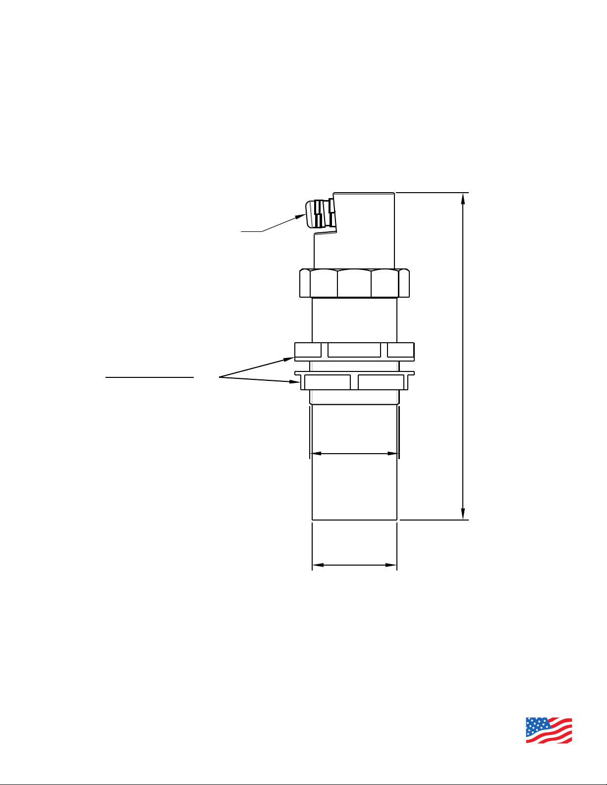
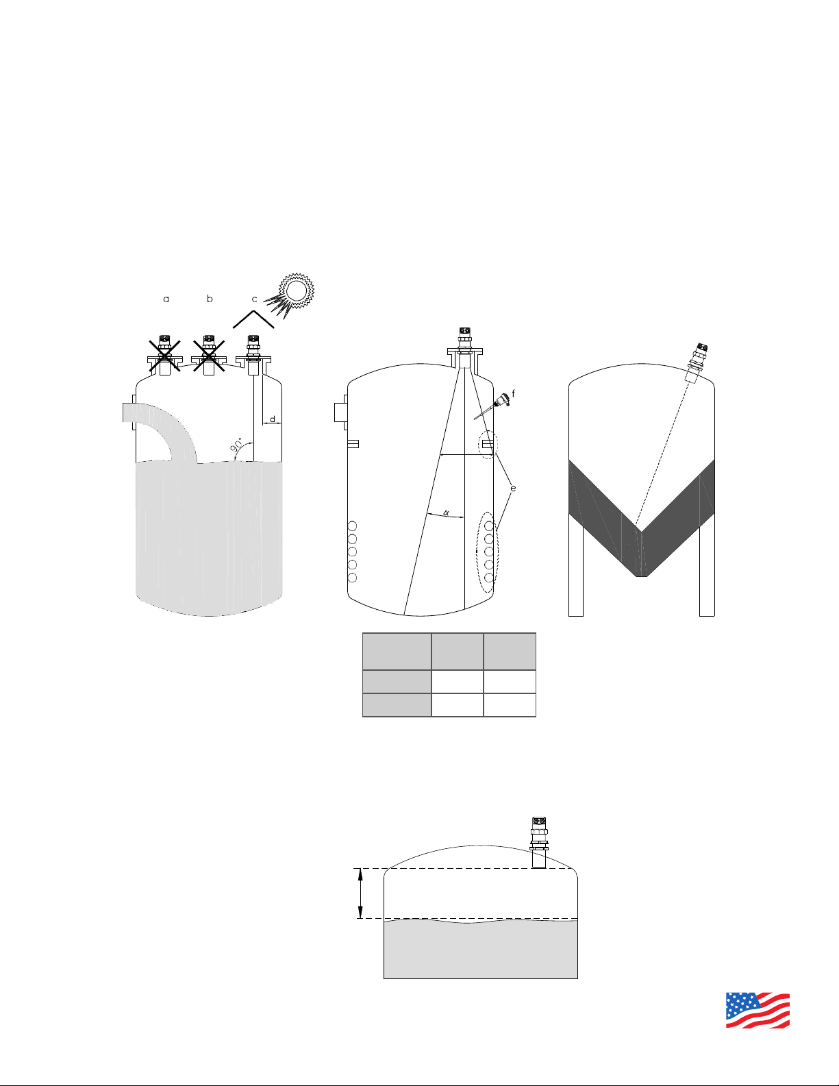
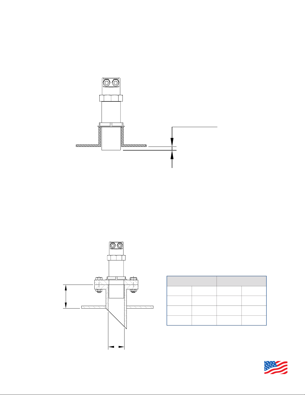
U5098 Series Ultrasonic Sensors Manual
099-MF179 - Warranty
Page. 3 of 40
www.madisonco.com
U5098 -warranty
Products supplied by Madison are guaranteed for a period of 12 (twelve) months from delivery date according
to the conditions specified in our sale conditions document.
Madison can choose to repair or replace the Product.
If the Product is repaired it will maintain the original term of guarantee, whereas if the Product is replaced it will
have 12 (twelve) months of guarantee.
The warranty will be null if the Client modifies, repair or uses the Products for other purposes than the normal
conditions foreseen by instructions or Contract.
In no circumstances shall Madison be liable for direct, indirect or consequential or other loss or damage
whether caused by negligence on the part of the company or its employees or otherwise howsoever arising
out of defective goods
WARRANTY
© 2020 Madison Company, Inc., MAD_MAN_099-MF179_RevA_060920
ECN #11618, Effective Date 06/09/2020, 099-MF179 Rev. A