Maggi BS 46 User guide

BS 46 MACHINE CODE 16430201
MANUAL CODE 00008030
EDITION 03/2018 - REV01
EN
BORING SYSTEM 46
WOODWORKING MACHINERY
ORIGINAL USE and MAINTENANCE MANUAL
THIS MANUAL SHOULD ALWAYS BE KEPT NEAR THE MACHINE FOR FUTURE REFERENCE

Page intentionally le t blank

CE Declaration of Conformity
The manufacturer
Maggi Technology S.r.l.
Via delle Regioni, 299 - 50052 Certaldo FI) ITALIA
Declares that the machine
is in compliance with all provisions pursuant the following directives:
2006/42/EC Machine)
2014/30/EU EMC)
2014/35/EU Low voltage)
and represents the technical file.
-Ce taldo - Issues date : The Gene al Manage
Giacomo Landi
Serial number plate label
The machine BORING SYSTEM
Model 46

Page intentionally le t blank

WE WISH TO THANK YOU FOR CHOOSING ONE OF OUR PRODUCTS
All the info mation, advices and impo tant wa nings fo a co ect use of the ma-
chine, have been inse ted into this manual. This manual also contains the ules
fo a co ect pe iodical maintenance to keep this machine in pe fect efficiency.
We suggest that all the chapte s of this manual a e tho oughly ead befo e you
use the machine fo the ve y fi st time.
INTRODUCTION
Some i formatio a d illustratio s i this ma ual may differ from the machi e i your
possessio , si ce all the co figuratio s i here t i the machi e complete with all the
OPTIONALS are described a d illustrated. Therefore, refer o ly to that i formatio
strictly co ected with the machi e co figuratio you have purchased. The
ma ufacturer i his pursuit of a policy of costa t developme t a d updati g of the
product may make a y modificatio s without a y prior otice.
This manual has been d awn up exclusively fo ou custome s’ use, gua anteeing that at the
date of issue it constitutes the latest update of the documentation elated to use of the
p oduct. Use of this manual is on full esponsibility of the use . The manufactu e does not
g ant any fu the gua antee fo any impe fections, incompleteness and/o ope ating
difficulties, exp essly excluding any esponsibility fo di ect o indi ect damage de iving f om
use of this documentation. MAGGI TECHNOLOGY ese ves the ight to make any
modifications to the p oduct desc ibed in this manual at any time without p io notice.
All ep oduction ights a e ese ved by MAGGI TECHNOLOGY.

1. SAFETY RULES AND GENERAL INFORMATION
1.1 RECOMMENDATION FOR USE AND MAINTENANCE
1.2 MACHINE IDENTIFICATIONS
2. OPERATIVE NOTES
3. MACHINE DESCRIPTION
3.1 USABLE TOOLS
3.2 MACHINE PARTS
4. EQUIPMENT, ACCESSORIES
5. SAFETY PROTECTION DEVICES
6. INDIVIDUAL PROTECTION DEVICES
7. TECHNICAL DATA
8. INTENDED USE
8.1 MATERIALS
8.2 IMPROPER USE
9. TRASPORT
10. OVERALL DIMENSION
11. INSTALLATION
11.1 PLACING THE MACHINE
11.2 LEVELLING
12. WORKING AREA
13. ASSEMBLING AND PRELIMINARY PREPARATION FOR WORKING
14. ASSEMBLING AND CHECKING PROCEDURE
15 MACHINE CONNECTIONS TO EXTERNAL POWER SUPPLY
15.1 CONNECTION TO ELECTRICAL POWER SUPPLY
15.2 PNEUMATIC CONNECTION
15.3 EXHAUST FAN CONNECTION
15.4 CONTROL DEVICES
15.5 WORKING RULES
16. DRILLING SETUP
16.1 WORKING RULES
16.2 ONE CYCLE OF DRILLING HORIZONTAL AND/OR VERTICAL
16.3 NOTES ON STARTING DEVICE
17. CHECK UP AND ADJUSTEMENTS
17.1 ELECTRICAL INSULATION PROCEDURE
17.2 PRELIMINARY CHECK UP
17.3 DRILLING DEPTH
17.4 ADJUSTING THE PARALLELISM OF SPINDLE HEADS
18. WORKING EXAMPLES
19. MAINTENANCE
20. COMMON FAILURES AND REMEDIES
20.1 DRILLS DO NOT ACCURATE
20.2 THE MOTOR WORKS BUT NOT THE DRILLS
20.3 THE HOLE IS NOT ACCURATE
21. ANOMALIES DURING NORMAL WORKING PHASES
21.1 BURN TRACES DUE TO DRILLS
21.2 THE DRILLED PIECES ARE NOT PARALLEL TO THE REFERENCE BAR
21.3 THE WORKING PIECES IS NOT BLOCKED BY THE SAFETY CLAMP
22. NOISE EMISSION
23. DUST EMISSION
24. PUTTING THE MACHINE OUT OF SERVICE
25. PNEUMATIC DIAGRAM
25.1 MACHINE AIR PRESSURE ADJUSTEMENT
26. ELECTRIC DIAGRAM
27 / 28. TERMS OF GUARANTEE / GUARANTEE CERTIFICATE
29. SPARE PARTS CATALOGUE
30. SPARE PARTS REQUEST
INDEX

NOTES

1. SAFETY RULES AND GENERAL INFORMATION
1.1 RECOMMENDATION FOR USE AND MAINTENANCE
In this manual we put into evidence all the ope ations fo a co ect use and o dina y maintenance of the
machine.
We st ongly ecommend not to make any othe type of wo k epai o ope ation not suggested in this manual.
We suggest also to keep this manual in a place whe e the use can easily find and ead it.
1.2 MACHINE IDENTIFICATION
The data imp essed in the plate placed on the left side of the machine (f om the point of view of the ope ato )
identify the machine itself.
When you eventually o de spa e pa ts o ask fo any suggestions fo use o maintenance, you have always to
t ansmit the model type and identification numbe contained in the plate.
It is absolutely fo bidden to emove the plate o modify the data it contains.
The following identification plate is placed on the bo ing system machine desc ibed into this manual:
ANY ADULTERATION OR REMOVAL OF SAFETY PROTECTION DEVICES CAN CAUSE
SEVERE DAMAGE. ANY REMOVAL, EXCLUSION OR MODIFICATION OF THESE
DEVICES IS STRICTLY FORBIDDEN.
YOU MUST VERIFY AND GUARANTEE THE PERFECT RUNNING OF SAFETY DEVICES
BY MEANS OF PERIODIC CHECKS. ANY DEFECT OR PROBABLE DRAWBACK MUST
BE IMMEDIATELY RESOLVED.
GENERAL INFORMATION ON THE MANUFACTURER
Manufactu e : MAGGI TECHNOLOGY S. .l.
Add ess: Via delle Regioni, 299 - 50052
Town: CERTALDO (FI)
Count y: ITALIA
Tel. +39 0571 63541
Fax. +39 0571 664275
E-mail: se vice@maggi-technology.com
Page
4

1) To ope ate the machine safely and co ectly, follow the indications contained in this manual ca efully and
sc upulously.
2) The machine will have to be ope ated only by pe sonnel who is both qualified and ove 18. People esponsi-
ble fo safety should make su e that the machine ope ato has ead and fully unde stood all the info mation
contained in this manual.
3) Maintenance inte ventions must be ca ied out only by pe sonnel who is both qualified and ove 18.
4) Pe sonnel esponsible fo outine and ext ao dina y se vicing must have a good knowledge of mechanics
and elect onics.
5) Keep away f om any moving pa t in the machine.
Neve touch the spindles and /o the d ills when the machine is ope ational.
6) Neve supe impose wood pieces to be wo ked. Always bo e one piece at a time, afte having adjusted the
machine co ectly.
3. OPERATIVE NOTES
4. DESCRIPTION OF THE MACHINE
Ou Bo ing Machines have been manufactu ed to make a se ies of holes at a fixed 32-mm distance between
cent es on wooden pieces (with maximum p ecision).
The pieces to be bo ed a e fed by the ope ato , who places them on the machine table. The ope ato will fi st
ca y out the equi ed adjustments by p essing the cont ol pedal. He will then lock the pieces into place with the
elevant hold down clamps and will sta t bo ing ope ations.
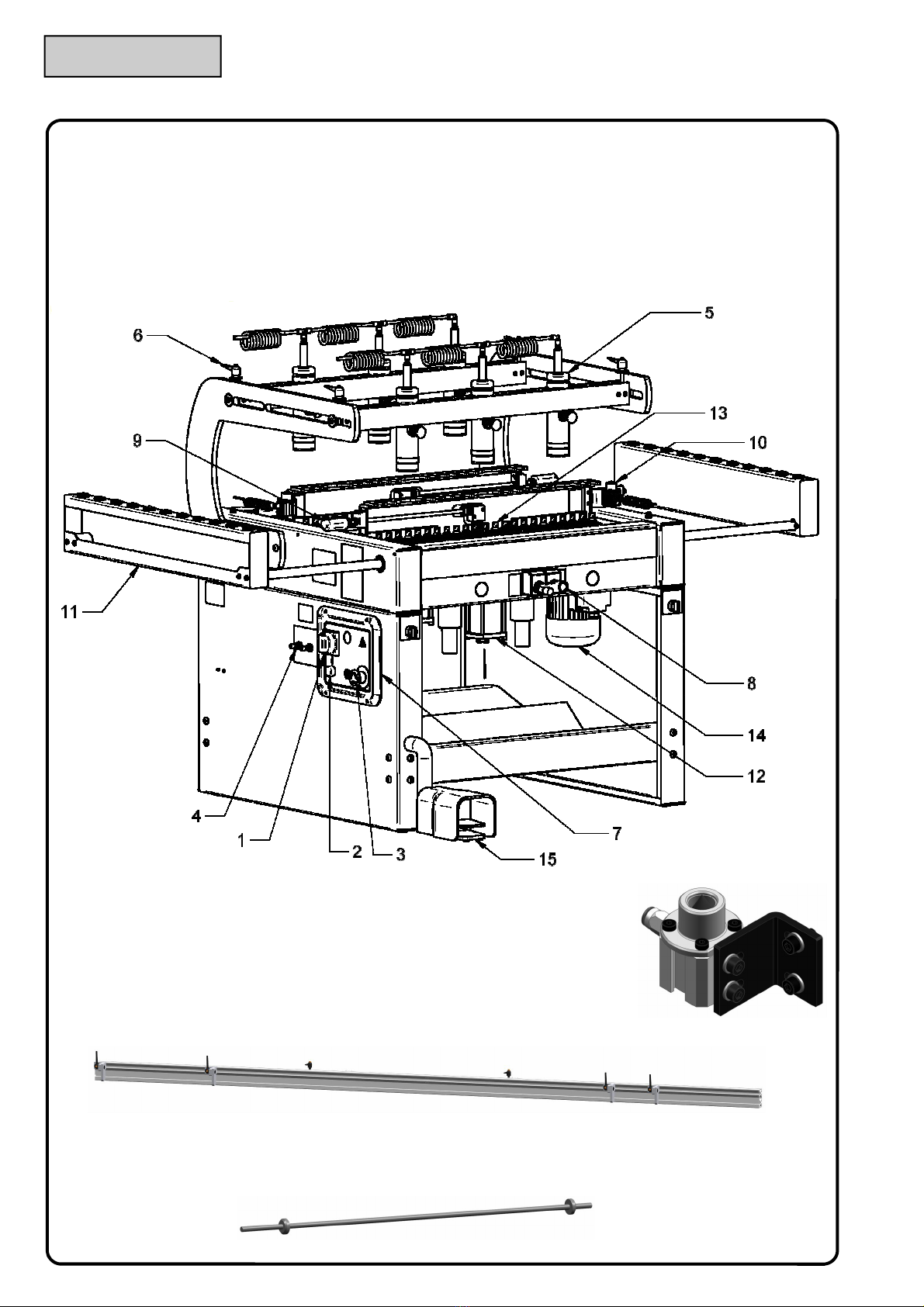
The following pa ts make up the machine:
A steel f ame
Spindlehead unit with t ansmission ( apid-attachment).
Hold down clamps unit to clamp the piece to be cut in a ve tical position.
Pneumatic system fo head positioning and head feed.
C ank mechanism to adjust spindles distance equipped with mechanical counte and device to adjust hole
depth f om 0 mm to 100 mm.
Rapid head-positioning device and head depth-adjustment device
Elect ic Powe plant complying with standa ds.
4.1 APPLICABLE TOOLS
D ills fo quick change spindles, 10 mm O. D. and 20 mm length shank ( Fig. A )
D ills up to 35 mm O. D. can be used ( Fig. B )
85 mm max useful length (connection excluded)
WOODWOORKING MACHINES CAN BE DANGEROUS
Fig. A Fig. B
ANY ADULTERATION OR REMOVAL OF SAFETY PROTECTION DEVICES CAN CAUSE SE-
VERE DAMAGE. ANY REMOVAL, EXCLUSION OR MODIFICATION OF THESE DEVICES IS
STRICTLY FORBIDDEN. YOU MUST VERIFY AND GUARANTEE THE PERFECT RUNNING OF
SAFETY DEVICES BY MEANS OF PERIODIC CHECKS. ANY DEFECT OR PROBABLE DRAW-
BACK MUST BE IMMEDIATELY RESOLVED.
Page
5

5. SUPPLIED EQUIPMENT
The machine comes with the following equipment to adjust the machine itself:
- N°6 Fast-positioning safety hold down clamps
- N°4 T.E. w enches sizes 6/7, 10/11, 12/13, 16/17.
- N°7 hexagon ing w enches sizes 2.5-3-4-5-6-8-10
- 3-mete extension fence with millimet ical scale and 4 movable stops (Fig. A)
- N°2 Refe ence pin fo line bo ing ( Fig. B )
The following equipment is optional:
- Refe ence fence 704 mm ( Fig. C )
4.2 MACHINE PARTS
1. Elect ical main switch
2. Elect ic powe line light
3. Eme gency pushbutton
4. Piston adjustment and d ills feed speed
5. Fast-positioning safety hold down clamps
6. Clamping handle fo hold down clamps ail
7. Elect ic cont ol boa d
Page
6
8. Cont ol handle fo d ills movement
9. D ills depth adjustment fo piece to be bo ed
10. Refe ence pin to epeat sets of holes
11. Suppo t olle
12. D ills feed cylinde
13. Spindlehead
14. Elect ic Engine
15. Pneumatic cont ol pedal
Fig. A
Fig. B
Fig. C

6. SAFETY PROTECTIONS DEVICES AND ADHESIVE WARNING
The main isk is due to the evolving d ills. To educe this isk to the minimum, ou machines have been
equipped with the following safety devices:
1) Emerge cy Pushbutto
It is located on the cont ol boa d in the f ont pa t of the machine. When it is p essed, all machine movements
a e halted immediately.
2) Set of Plates
They contain an accu ate desc iption of safety p ecautions and indications on how to ope ate the machine co -
ectly and make it possible to identify the machine pa ts. One of these plates contains the identification data
and the se ial numbe of the machine itself.
3) Side Protectio s
They p event the ope ato f om inse ting his/he hands accidentally into the machine when the spindlehead is
moving.
4) Safety hold dow clamps (pate ted)
They emain eithe on the machine table su face o on the al eady positioned piece to be wo ked, thus p e-
venting the ope ato f om accidentally placing his/he hands unde one of them.
5) EL Safety Device
No- etu n coil to p event accidental sta ting of the machine.
CAUTION SYMBOL: ALL OPERATIONS MARKED WITH THIS SYMBOL
ARE DANGEROUS FOR THE OPERATOR. AS A RESULT THE OPERATOR
MUST PAY THE GREATEST ATTENTION WHILE CARRYING THEM OUT.
Page
7
WARNING SYMBOL
ALL THE OPERATIONS HIGHLIGHTED WITH THIS
SYMBOL ARE DANGEROUS TO THE OPERATOR;
PLEASE BE VERY CAREFUL IN DOING THESE OP-

Page
8

Page
9
8. TECHNICAL DATA
7. INDIVIDUAL PROTECTION DEVICES AND RESIDUAL RISKS
Despite all adopted safety p otection devices, following situations may be dange ous:
- fall o th ow of wood slive du ing wo king ope ation
- entangling pa ts of clothes in moving pa ts of the machine
- dange of fi e
- dange of elect ocution
- dange of damage due to noise emission
- dange of damage due to dust emission
To p event isks du ing placing, installation, adjustment, use, o dina y and ext ao dina y maintenance, we
st ictly ecommend to use the following individual p otection devices:
- gloves (fo example du ing machine pa ts handling)
- anti-c ushing and anti-sliding shoes
- glasses o face-shields against chip o wood slive du ing wo king o cleaning ope ation of the machine
- anti-dust masks
Mo eove , the clothes must be suited to avoid dange of:
- catching
- d agging
- c ushing
- sliding
- ab asion
- contact lenses a e p ohibited
Fo fu the info mation and ecommendation please efe to chapte . OPERATIVE NOTES.
NEVER LEAVE THE MACHINE UNATTENDED WHEN
CONNECTED TO THE ELECTRICAL POWER SUPPLY
GENERAL
WEIGHT 370
SIZE ( mm ) 950 x 970 x 1150
SPINDLE RIGHT / LEFT ATTACHMENT SIZE 10 mm
MAX WIDTH FOR HOLES IN A ROW 0 / 645
MINIMUM WIDTH BETWEEN HEADS 145 mm
MAX THICKNESS UNDER HOLD DOWN CLAMPS 75
OVERALL NUMBER OF SPINDLES 23 + 23
MAX BORING DEPTH ( mm ) 55
MAXIMUM BORING DISTANCE BETWEEN CENTRES ( mm ) 704
DISTANCE BETWEEN CENTRES BETWEEN EACH SPINDLES ( mm ) 32
SPINDLES REVOLUTIONS RPM 2800
NUMBER OF ENGINES + ENGINE POWER ( Kw ) N° 2 x 1,1 Kw
ATTACHMENT TYPE T= THREADED R= RAPID R

Page
10
9. INTENDED USE
9.1 MATERIALS
The bo ing system machine has been designed and built to d ill the following mate ials:
- solid wood
- m.d.f.
- panels of shaving wood, laminated wood, ennobled wood, etc.
The maximum panel thickness is 80 mm and its maximum dimensions a e those desc ibed in chapte 8.
- Othe mate ials, diffe ent f om the ones desc ibed above, can be machined only afte the w itten app oval of
the manufactu e . In pa ticula it is not allowed to machine mate ials having toxic o dange ous substances
fo ope ato ’s health and safety, metals o othe mate ials that can modify the co ect wo king of the machine
o cause fi e o explosion..
- Any modification is fo bidden without the w itten autho ization of the manufactu e .
- It is not allowed to tampe with the safety p otection devices.
10. TRANSPORT
The bo ing machine is packed in a wooden box and/o in ca dboa d and nylon. It is possible to move it by
means of:
Fo klift
c ane
t anspallet
Weight data a e w itten in chapte 8. Befo e moving the machine ve ify that the enti e su ounding a ea is f ee
of obstacles. In case of stocking, the machine must be kept in d y places, away f om ain, snow o humidity.
Du ing all moving ope ations we ecommend to be ext emely ca eful to avoid dange of damage fo pe sons,
things and the machine itself.
9.2 IMPROPER USE
Any ope ation that does not comply with the inst uctions given he ein is to be ega ded as imp ope use.
Mo eove :
WE ADVISE YOU NOT TO lay tools against o on the machine fo any eason whatsoeve du ing machine
installation, use o maintenance.
WE ADVISE YOU NOT TO get on the machine o on any of its pa ts.
The ma ufacturer ca ot be co sidered liable for a y damage caused
to people, a imals or property resulti g from improper use of the
machi e.

11. MACHINE SIZE
Page
11
Ref. A B C
Mod.4632 950 970 1150
12. INSTALLATION
12.1 PLACING THE MACHINE
The machine must be placed on a stable plain su face, capable to suppo t the weight of the machine itself;
any possible diffe ence in height must be in confo mity with building ules. When the machine has to be
placed on aised plain su face (highe floo ) the load-bea ing slab must be adequate to the weight of the ma-
chine.
Put the machine in the ight place, as equested ope ative equi ements, whe e it is easy to connect it to
elect ical and pneumatic powe supply.
Put the machine in a place whe e the e is enough lighting to see eve y pa t of the machine itself.
We suggest also to a ange an exhaust fan nea by the machine to clean it pe iodically.
12.2 LEVELLING
Adjust the levelling feet so that the machine is pe fectly leaned on the floo , then align the wo king table of
the machine by using a spi it level.
Befo e going on with levelling, tighten the alignment pins into the th eaded holes of the bed f ame, emove
the p otective oil film f om planes and eve y not painted su face, by using pet oleum o ke osene only.
Do not use any solvent as gasoline and diesel oil, because they can damage the paint, making it dull, o oxi-
dize othe pa ts.

Page
12
13. ASSEMBLING AND CHECKING PROCEDURE
The Bo ing System 23V bo ing machine is packed in a la ge wooden box. We st ongly suggest to apply a
ca eful and co ect p ocedu e to t anspo t the box to the a ea whe e the bo ing machine will be installed.
Remove the two fixing de-
vices, which lock the ma-
chine to the pallet, placed
on the lowe pa t of the
machine f ame by un-
sc ewing the sc ews (see
figu e on the left)
Now it is possible to sepa-
ate completely the ma-
chine f om the packaging.
T anspo t and put the machine in the place selected
fo wo king. Please be ca eful in doing this p ocedu e
and follow the inst uctions desc ibed in chapte 10
Level the ma-
chine loosening /
tightening the
T.E. sc ews
placed on the
lowe pa t of the
machine f ame
(see figu e on the
left).
A B
C
D
E F
G
H

Page
13
The packaging contains also the long fence g oup, clamping unit, clamp holde suppo t
and a ca dboa d
box with some othe accesso ies inside, as shown in the figu e below.
The box co tai s the followi g accessories:
Dowel hole bo ing machine use and maintenance manual
W enches Kit
n° 6 clamping unit
n° 4 Movable stop unit
n° 1 handle
n° 8 long fence pins
n° 4 leve M8x20
n° 4 kashe
n° 4 sc ew vtstei M8x20
Remembe to assemble the long
fence g oup and the movable
stops following the p ocedu e de-
sc ibed in chapte 15.6
ATTENTION
Machi e co ectio :
we strongly suggest to
care ully ollow the procedures
described in chapter 16
Drilli g set-up procedure:
care ully ollow the procedures
described in chapter 17
The next step consists of machine con-
nection to:
Elect ic powe supply (see chapte
15.1 )
Pneumatic powe supply ( see chapte
15.2 )
Pneumatic powe supply connection point
Elect ic powe supply connection point

14. WORKING AREA
To use the machine p ope ly, the a eas indicated in the pictu e below must be left f ee.
Page
14
Never leave the machi e u atte ded whe
co ected to the electrical power supply
15. ASSEMBLY AND PRELIMINARY PREPARATION FOR SET UP
The machine is delive ed pa tially assembled, so it is necessa y to mount all those pa ts left not assembled
fo packaging easons.
The buye must ve ify that all the machine pa ts a e safe and not damaged afte t anspo tation, befo e going
on with assembling.
In pa ticula we suggest to ve ify the most delicate pa ts, as elect ical o mechanical components, pneumatic
tubing o the safety p otection devices of the machine itself.
Afte assembling, it is necessa y to clean all su faces f om p otective oil so that the wo king pieces emain
clean du ing wo king ope ations.
SAWDUST REMOVAL
The emoval of sawdust and wood sc ap, has to be effected in acco dance to the cu ent ules of the count y
whe e the machine is installed.
We suggest to ask the qualified body of the count y whe e the machine is installed fo the ules conce ning
this emoval to know exactly how to behave p ope ly.
16. MACHINE CONNECTION TO EXTERNAL POWER SUPPLY
Afte machine assembling and installation, connect it with:
Elect ical powe supply
Pneumatic powe supply
Dust suction system
ATTENTION: THE MACHINE IS DELIVERED WITHOUT EXHAUST SYSTEM. THE
USER HAS TO INSTALL A PROPER EXHAUST FAN DEPENDING ON THE TYPE OF
USE, THE MATERIAL AND THE TIMING OF USE OF THE MACHINE. THIS SYSTEM
HAS TO KEEP THE DUST CONCENTRACTION BELOW THE VALUE ALLOWED BY
THE LAW OF THE COUNTRY WHERE THE MACHINE IS INSTALLED.

16.2 PNEUMATIC CONNECTION
1) Connect the machine to the comp essed ai system and make su e that the connection tube is compatible
with the one p ovided alongside the machine itself and located on the lub ication-filte - egulato unit at the back
of the machine, in the lowe ight-hand side.
Wo king p essu e should ange between 6 and 7 ba .
2) The lub ication-filte - egulato unit is made upby:
A) A filte , whose function is to pu ify ai f om dust and humidity that might damage the valves o gaskets in
pneumatic cylinde s.
B) A egulato that adjusts comp essed ai wo king p essu e by keeping this value within the above-
mentioned limits.
C) A lub icato that puts a dete mined amount of oil into the system to lub icate cylinde s, valves, gaskets and
moving pa ts.
Page
15
16.1 CONNECTION TO ELECTRICAL POWER SUPPLY
To gain access to the machine elect ic system, open the main boa d doo by loosening the sc ews on the
f ont of it. We ecommend not to connect the machine to the elect ical powe supply until it is not co ectly
placed in the ight place. Befo e connecting the machine to the elect ical powe supply, it is necessa y to ve -
ify that the elect ical system co esponds to the following necessa y powe and safety equi ements:
G ounded equipotential elect ical system
P esence of fuses o p otection switches against sho t ci cuits on eve y conducing cable R-S-T, except
the g ounded one
The elect ical powe system must be in confo mity with CEI 64.8 (CENELEC HD 384, IEC364-4-41)
ules
Voltage and f equency fo the moto s a e specified on the plates placed on them
Connect the powe supply cable to R-S-T te minals
Automatic p otection devices installed upst eam espect to the machine; they have to be coo dinated to
gua antee the automatic b eak acco ding to above mentioned ules.
The elect ical connection is done by th ee-phase plug (o single-phase plug, depending on the panel).
The cable fo g ound connection is yellow-g een.
The tole ance of admissible voltage is +/-10%
When voltage is applied to the elect ical powe supply, check that the spindles otation di ection is the one
w itten in the plate placed on the head (Black=Right; Red=Left).
If the otation di ection does not match the one imp essed in the plate, please inve t the connection cables to
th ee phase powe supply. Fo any info mation please see the elect ical diag ams included in this manual.
Atte tio : we stro gly recomme d that the
co ectio to the electrical power supply is
do e by tech ical qualified perso el o ly.

EMERGENCY PUSHBUTTON
TO HALT THE ENGINE (THE
BUTTON IS NOT AUTOMATI-
CALLY RELEASED)
By p essing this button all elect ical functions of the machine
a e switched off.
To switch elect ic functions on, tu n the mush oom pushbutton
in the di ection indicated by the a ows.
1
PUSH BUTTON TO MAKE EN-
GINE OPERATIONAL; MAIN
SWITCH
1 - It gets the engines eady to be sta ted and hence it gets the
spindles eady to otate du ing the wo king cycle.
It the switch is tu ned on powe is supplied
2
ON/OFF POWER INDICATOR
PILOT LIGHT
1 - If the light is on powe is available.
2 – If the light is off powe is not available. 3
FEED SPEED ADJUSTMENT
(HEAD 1 a d HEAD 2)
1 – It adjusts d ills bo ing feed speed
4
(Head 1)
(Head 2)
16.5 CONTROL PANEL
The cont ol panel is located on the left-hand side of the machine:
16.3 MACHINE STARTING
The ope ato ’s site and the cont ol boa d a e located in the machine elect ical cont ol panel. The ope ato will
position the wood pieces on the wo king table afte having adjusted stops.
15.4 WORKING CYCLE
Afte having p og ammed the machine, follow the inst uctions given in the following pa ag aph to sta t the
wo king cycle:
1) Tu n the main switch (2) and set it to position 1. The machine is eady to sta t the wo king cycle.
2) P ess the pedal (A); the spindles will tu n and the head will sta t the wo king cycle while the hold down
clamps will clamp the piece.
3) If the pedal is eleased, the head will etu n in its initial position and the spindles will stop.
4) Hold down clamps will elease the block when the head etu ns to its initial position.
Should you need to inte upt the wo king cycle, p ess the eme gency pushbutton (1)
Page
16
4
3 1
2
A
This manual suits for next models
1
Table of contents
Other Maggi Industrial Equipment manuals