Magna-Matic MAG-9000 Series User manual

Original Instructions
for Magna-Matic Lawn Mower
Blade Sharpeners
MAG-8000 SERIES [gen6]
MAG-9000 SERIES [gen7]

2
MAG-9000 LAWNMOWER BLADE SHARPENER
THANK YOU,
We sincerely appreciate your decision to make Magna-Matic your
lawn mower blade sharpener. We understand there are other choices in the
marketplace, and we are extremely condent that after the rst few blades
you sharpen, it will be evident you’ve chosen the best machine for the job.
Rest assured that if you have a question or problem you will have complete
customer support for all of our products.
800-328-1110 (USA & CANADA) or 920-564-2366
http://www.magna-matic.com
BOX INVENTORY
• MAG-9000 sharpener main body
• Vacuum grit guard (9000-50)
• Grinding wheel (9000-23) mounted
• Spanner wrench (9000-21)
• Arbor wrench (9000-53)
Please be sure all the items are in the box and inspect
for shipping damage, or for missing parts. Contact
Magna-Matic right away to remedy any problems due
to shipping. 800-328-1110

3
BOX INVENTORY
• MAG-8000 sharpener main body (with grit guard)
• Grinding wheel (9000-35)
• Grinding wheel (8000-30)
• Crank handle
• Flat worktable insert
• Rounded worktable insert (mounted on machine)
• Spanner wrench (9000-21)
• Arbor wrench (9000-53)
Please be sure all the items are in the box and inspect for
shipping damage, or for missing parts. Contact
Magna-Matic right away to remedy any problems due to
shipping. 800-328-1110
IMPORTANT - There is a transport bolt that must be
removed before use! The bolt goes through the two uprights and
the pivot plate. If this bolt is not removed it will be impossible to adjust
the grinding wheel. See page 6.

4
Before handling any equipment read
and understand the instructions.
THE SAFE WAY IS THE ONLY
WAY TO GRIND!
Grounding Instructions - This tool must be grounded while in use to protect the operator from electric shock. The tool is equipped
with an approved three conductor cord and three prong grounding type plug to t the proper grounding type receptacle. The green (or
green and yellow) wire is the grounding wire.
Extension Cords - Use only three wire extension cords which have three prong grounding type plugs and three pole receptacles which
accepts the tool’s plug. Replace or repair damaged cords.
Keep Work Area Clean - Clean benches and oors to prevent slip, trip, or falls.
Consider Working Environment - Don’t use power tools in damp or wet locations. Keep work area well lit. Don’t expose power tools to
rain. Do not use tool in presence of ammable liquids or gases.
Keep Children Away - All visitors should be kept a safe distance from the work area. Do not let visitors have contact with the tool or the
extension cord.
Store Idle Tools - When not in use, tools should be stored in dry, high or locked-up places out of reach of children.
Do Not Force Tool - It will do the job better and safer at the rate for which it was designed.
Do Not Over-Reach - Keep proper footing and balance at all times
Use Safety Glasses - Also face or dust mask-wrap around goggles, or other eye protection.
Wear Proper Apparel - Do not wear loose clothing or jewelry that can get caught in moving parts. Gloves and non-skid footwear are
required when working. Wear protective hair covering to contain long hair.
Do Not Abuse Cord - Never carry tool by cord or pull it to disconnect from receptacle.
Keep cord from heat, oil, and sharp edges.
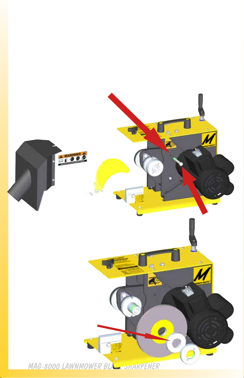
Disconnect Tool - When not in use; before servicing; when changing grinding wheels.
Avoid Accidental Starting - Don’t carry plugged in tool. Be sure switch is o when plugging in.
Grinding Wheels - Use only grinding wheels having a maximum operating speed of 5500 RPM. KEEP GUARDS IN PLACE.
Guard Against Electrical Shock - Prevent body contact with grounded surface. For example: pipes, radiators, etc.
Stay Alert - Watch what you are doing. Use common sense. Do not operate tool when you are tired, or under the inuence of any
drugs or alcohol.
Check Damaged Parts - Before further use of the tool, a guard or other part that is damaged should be carefully checked to determine
that it will operate properly and perform its intended function. Check for alignment of moving parts, breakage of parts, mounting and
any other condition that eect its operation. All parts should be properly repaired or replaced. Do not use this tool if the switch does
not turn it on or o.
Never Leave Tool Unattended - Turn the power o. Don’t leave the tool until it comes to a complete stop.
Read “A Primer on Grinding Wheel Safety” http://www.magna-matic.com
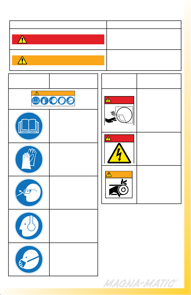
WARNING
WHEN USING ELECTRIC TOOLS, BASIC
SAFETY PRECAUTIONS SHOULD ALWAYS
BE FOLLOWED TO REDUCE
THE RISK OF FIRE, ELECTRIC SHOCK,
AND PERSONAL INJURY.
CAUTION LAWN MOWER BLADES HAVE SHARP
EDGES - ALWAYS WEAR PROTECTIVE
GLOVES AND SAFETY GLASSES!

5
SAFETY LABELS
SAFETY COLOR DEFINITION
DANGER Interaction with the hazard will
cause severe injury or death.
WARNING Interaction with the hazard could
cause severe injury or death.
SAFETY
ICON DEFINITION
WARNING
Read all included
manuals and
bulletins included with
this equipment.
Always wear protective
gloves when operating
this equipment.
Gloves are required.
Always wear protective
eye wear when operating
this equipment.
Eye protection
required.
Always wear protective
hearing protection when
operating this equipment.
Hearing protection
required.
Always wear respiratory
protection when operating
this equipment.
Respiratory protection
required.
SAFETY
ICON DEFINITION
DANGER
Keep clear of the
grinding wheel.
Contact will cause
severe cuts or
abrasions.
Always keep safety
guards in place.
DANGER
Disconnect power
before servicing
machine
Always keep safety
panels in place.
WARNING
Keep clear of pulleys
and belts. Contact
will cause severe
injury.
Always keep safety
guards in place.

6
MAG-8000 LAWNMOWER BLADE SHARPENER
ASSEMBLY
IMPORTANT - There is a transport bolt that must be removed
before use! The bolt goes through the two uprights and the pivot plate. If this
bolt is not removed it will be impossible to adjust the grinding wheel. First
remove the grit guard, loosen the 5/16” bolt, and replace it with the plastic knob.
Then pull the grit guard outward and set it aside.
MOUNTING THE 1/2”
WIDE WHEEL, for
sharpening mulching
blades.
The 1/2” wide grinding
wheel requires the arbor
spacer.
The 1/2” wide wheel
will be in-line with the
rounded mulching blade
worktable insert. Be sure
the arbor spacer
(8000-27) is used as
shown in the image.
Use (2) 1/2” wrenches to remove the
transport bolt. Connect the crank handle
to the adjustment rod. Align the set
screw in the crank handle to the at on
the adjustment rod and tighten the set
screw (1/8” allen). You may need to
make a half-rotation on the crank handle
to loosen the pressure on the transport
bolt to remove it.

7
ASSEMBLY
TESTING THE MAG-8000
Before turning the unit on, test the unit by checking if the grinding wheel moves freely.
Ensure the MAG-8000 ON/OFF switch is in the OFF POSITION, plug the MAG-8000 into
a 20 amp, 110 volt outlet. Switch the ON/OFF switch to the ON POSITION to test the
motor. The motor should achieve FULL speed in 1-2 seconds. If it does not,
(see page 19) or contact MAGNA-MATIC (800-328-1110).
Steps to connect the grit guard to the MAG-8000.
1. The yellow ACTIVE GUARD must be on the inside of the black steel
guard by the motor.
2. The top lip of the grit guard must be on top of the yellow body plate of
the MAG-8000.
3. Slide the grit guard assembly into the MAG-8000 and the
interlocking tabs and lips will engage keeping the guards solid.
4. Screw the plastic knob into the threaded hole to hold the grit guard
assembly in place.
5. See top image on page 6, for a view on attaching the grit guard.
MOUNTING THE 1”
WIDE WHEEL, for
sharpening
straight-edged blades.
DO NOT USE the arbor
spacer when using the 1”
wide grinding wheel. Only
use the arbor nut.
WARNING
WHEN USING ELECTRIC TOOLS, BASIC
SAFETY PRECAUTIONS SHOULD ALWAYS
BE FOLLOWED TO REDUCE
THE RISK OF FIRE, ELECTRIC SHOCK,
AND PERSONAL INJURY.

8
MAG-8000 LAWNMOWER BLADE SHARPENER
ANGLE ADJUSTMENT
IMPORTANT - ALWAYS turn the MAG-8000 OFF when
changing or adjusting worktable inserts.
New [gen6] worktables (blade rest)
The new change to the MAG-8000 [gen6] is the implementation of worktable inserts. This new design
allows for future inserts for specic blades, and dierent size worktables. Additionally the worktable
insert provides the ability to dial in angles from 25º to 45º.
The worktable inserts slide into a fixed vice that is clamped by tightening a 5/16” bolt with the hex end
of the supplied spanner wrench or a 1/2” wrench.
The black flat worktable insert is for straight flat. (conventional blades)
The steel rounded worktable insert is for curved cutting edge. (mulching blades)
ABOVE: Worktable
position decal
RIGHT: Angle information
decal
Angle Indicators
These two decals are located on the
MAG-8000 they indicate worktable
positions required to achieve the listed
cutting edge angles.
30 degrees is the ONLY angle where the
worktable remains in one position over
the life of a grinding wheel. All other
angles require that the worktable be
moved to a position corresponding with
the chart on the MAG-8000. Use the
chart on the MAG-8000 (shown to the
right) to move the worktable insert when
the grinding wheel is at a diameter listed.
Note: the black
plastic wear plate is
reversible.
WARNING
WHEN USING ELECTRIC TOOLS, BASIC
SAFETY PRECAUTIONS SHOULD ALWAYS
BE FOLLOWED TO REDUCE
THE RISK OF FIRE, ELECTRIC SHOCK,
AND PERSONAL INJURY.

9
Worktable Set-up
The base of the worktable inserts are slotted.
Slide the worktable insert into the vice (shown below)
Once in place at the desired angle position, tighten the bolt in the worktable vice.
DO NOT OVER-TIGHTEN (only a 1/4 to 1/2 turn is required to clamp the insert.)
The spanner wrench has a 12 point hex wrench used for the bolt to tighten the insert in place.
A 1/2” wrench or socket can also be used.
Worktable Alignment
(Shown below) Align the front of the
insert to the line of the letter of the angle
position you desire. In the image the
insert is aligned to the letter B, which is a
45º @ 6” diameter grinding wheel. The
red arrow shows the front of the insert,
which is the part to align.
Left: View of the
spanner wrench used
to tighten the vice to
hold worktable inserts.

10
MAG-8000 LAWNMOWER BLADE SHARPENER
30 DEGREE ANGLE
MOST BASIC ANGLE - READ FOLLOWING INFO!
30 degrees is the most consistent and easiest angle to maintain in the
MAG-8000. It is also the industry average angle on most blades. If you are
looking for the most simple way to consistently sharpen your lawn mower blades,
use 30 degrees according to following instructions.
Align the worktable insert (at or rounded) to the 30º arrowed mark on the
worktable vice (see yellow decal in image below). This will make the insert
square to the vice (flush on back and front). Tighten it in place with the hex end of
the spanner wrench.
Lower the grinding wheel with the black crank handle on the top of the
MAG-8000, lower it as close as possible to the worktable without touching the
worktable (approx 1/32”), so you can just see a small space.
The worktable insert DOES NOT need to be moved to compensate for grinding
wheel diameter as other angles do. Simply keep lowering the grinding wheel
within a 1/32” from the worktable. See the red arrow, showing the approx. 1/32”
distance from the worktable to the wheel. Maintain this closeness to the
worktable to maintain the desired angle.

11
Visual example of setting a 45º over the life of a
grinding wheel
Due to the changing geometry of a grinding wheel’s diameter it is necessary to move the
worktable insert to dierent positions over the life of the wheel. Each image below shows
one inch diameter grinding wheel increments. Starting at the left is a new 7” diameter
wheel and the far right shows a used wheel at 3.25” diameter. As the grinding wheel wears
(becomes smaller in diameter) the worktable MUST be moved to maintain a consistent angle
according to the charts provided on the MAG-8000.
For example if a wheel is at 6.5” diameter move the worktable insert to half-way between
A and B. Remember to also adjust the wheel down to the worktable as shown in all the
images.
CUTTING EDGE ANGLE TOLERANCE:
Due to the changing variables of the grinding wheel diameter, and different blade thickness
the charted angles will have an approximate tolerance of 1-2 degrees.
If you have worn out - or accidently ground the plastic worktable - please note you may
rotate the worktable and use the other side.
7” dia.
6” dia.
5” dia.
4” dia.
3.25” dia.
25º Cutting Edge Angle
Loosen the vice bolt and push the work-
table insert as it will go toward the motor
until you hit a stop. Tighten the vice bolt
then lower the wheel down to the work-
table. Both 25 and 30 degrees do not
require movement to dierent “letter
positions” based on the diameter of the
wheel.

12
MAG-8000 LAWNMOWER BLADE SHARPENER
MULCHING BLADES
Be sure to wear protective clothing before handling and sharpening lawn
mower blades. Wear safety glasses and protective gloves. Always de-burr the
underside of the blade, prior to sharpening the blade.
BLADE & SHARPENER PREPARATION
1. Clean the blade to its base material, using the MAG-12008 blade cleaner, or
alternate cleaning process. Inspect the blade for fractures.
2. Check the straightness with the gauge rod of the MAG-1000 blade balancer
(never straighten bent blades)
3. Obtain a balance reading from the MAG-1000 to indicate the light end of the
lawn mower blade. Once the light end is sharpened, that end is complete.
The heavy end is used to remove material for balance. See MAG-1000
instructions for more details on blade balancing.
4. The MAG-8000 will require the 1/2” wide grinding wheel to sharpen a
mulching blade. Mount the 1/2” wide wheel on the MAG-8000. (see page 6)
5. Place the rounded worktable insert into the worktable vice. Position it at
the desired angle according to page 10-11. Tighten the vice bolt with the
spanner wrench.
6. Review pages 10 and 11 to adjust the MAG-8000 to the desired angle.
MULCHING BLADE SHARPENING
1. Switch the ON/OFF switch to ON position
2. When sharpening a mulching blade, you will start with the inside of the
cutting edge and pull the blade out towards you, taking one pass at a time.
3. Pull the blade over the worktable, it is very important that you put more
downward pressure on the blade, the underside of the blade MUST ride the
curved worktable, this will follow its curves. Lessen the inward pressure so
that the blade may move to and from the grinding wheel as the blade rides
up and down the curved worktable. Do not use extreme pressure into the
grinding wheel, let it ride over the curves.
4. Use even pressure to achieve an even stream of sparks.
5. When using the MAG-8000 for mulching blades keep the blade level, and
perpendicular to the rotation of the grinding wheel. Pay close attention to the
TIP of the blade, to create a pointed TIP see pages 34-35. You may use the
flat worktable for doing the TIPS of mulching blades, if you prefer.
WARNING
WHEN USING ELECTRIC TOOLS, BASIC
SAFETY PRECAUTIONS SHOULD ALWAYS
BE FOLLOWED TO REDUCE
THE RISK OF FIRE, ELECTRIC SHOCK,
AND PERSONAL INJURY.
CAUTION LAWN MOWER BLADES HAVE SHARP
EDGES - ALWAYS WEAR PROTECTIVE
GLOVES AND SAFETY GLASSES!

13
In these images the safety guards have been removed to provide a better
view of blade position in the MAG-8000.
NEVER OPERATE WITHOUT GUARDS IN PLACE
MULCHING BLADES
Always maintain
contact with the
worktable and
underside of the
blade.
Allow the blade to twist as the
worktable follows the underside.
You will have more
control if you only
“pull” mulching
blades across the
grinding wheel. It
is critical with both
blade types that
the operator keeps
downward pressure
on the blade, this will
prevent chattering
and keep the
grinding wheel “true”
or round.
Training Video

14
MAG-8000 LAWNMOWER BLADE SHARPENER
CONVENTIONAL
BLADES
Be sure to wear protective clothing while handling and sharpening lawn mower
blades. Wear safety glasses and protective gloves. Always de-burr the
underside of the blade, prior to sharpening the blade.
BLADE & SHARPENER PREPARATION
1. Clean the blade to its base material, using the MAG-12008 blade cleaner, or
alternate cleaning process. Inspect the blade for fractures.
2. Check the straightness with the gauge rod of the MAG-1000 blade balancer
(never straighten bent blades)
3. Obtain a balance reading from the MAG-1000 to indicate the light end of the
lawn mower blade. Once the light end is sharpened, that end is complete.
The heavy end is used to remove material for balance. See MAG-1000
instructions for more details on blade balancing.
4. It is best to use the 1” inch wide grinding wheel to sharpen a conventional
blade. Mount the 1” wide grinding wheel on the MAG-8000. (see page 7)
(note the 1/2” wide wheel can be used on conventional blades, but the 1” is
more cost eective)
5. Place the at worktable insert into the worktable vice. Position it at the
desired angle according to page 10-11. Tighten the vice bolt with the
spanner wrench.
6. Review pages 10 and 11 to adjust the MAG-8000 to the desired angle.
CONVENTIONAL BLADE SHARPENING
1. Switch the ON/OFF switch to ON position
2. Place the conventional blade on the worktable, you should push and pull the
blade across the grinding wheel.
3. Keep firm downward pressure on the top of the blade so that
contact is maintained with the worktable. This is important because the
blade edge-angle is referenced off the worktable.
4. The force into the grinding wheel should be substantial resulting in a
continuous stream of sparks and a deep smooth grinding sound.
5. The grinding process should be continuous without interruption until finished.
(See pages 34-35 for blade geometry info)
WARNING
WHEN USING ELECTRIC TOOLS, BASIC
SAFETY PRECAUTIONS SHOULD ALWAYS
BE FOLLOWED TO REDUCE
THE RISK OF FIRE, ELECTRIC SHOCK,
AND PERSONAL INJURY.
CAUTION LAWN MOWER BLADES HAVE SHARP
EDGES - ALWAYS WEAR PROTECTIVE
GLOVES AND SAFETY GLASSES!

15
Keep constant pressure downward to
maintain flat contact with the worktable.
Slide the blade back and
forth across the grinding wheel.
Apply pressure into the
grinding wheel to remove
material.
Overhead view of blade approach - applies to both
conventional and curved edge mulching blades.
The above diagram shows the application of movement and force to the blade
during sharpening of a conventional blade.
TIP: Use 3-4 of
your ngers to
apply the down-
ward pressure,
and your thumb
to apply the in-
ward pressure.
Right-handed Blade Left-handed Blade
Training Video

16
MAG-8000 LAWNMOWER BLADE SHARPENER
Loosen
Tighten
GRINDING WHEEL
REPLACEMENT
Be sure the MAG-8000 power cord is unplugged. Remove the grit guard
see (page 6.) Locate your spanner wrench and arbor wrench
(both supplied by Magna-Matic.) The arbor wrench ts into a square
notch in the arbor, behind the grinding wheel, and the spanner wrench ts
into the two holes in the arbor nut. See diagrams below.
Always inspect grinding wheels for possible damage - never mount a
cracked grinding wheel. DO NOT OVER-TIGHTEN ARBOR NUT -
ONLY LIGHT PRESSURE TO TIGHTEN. The motor will tighten the
arbor nut every time the sharpener is turned on.
For optimum performance use only grinding wheels specied by
Magna-Matic. All NORTON® brand grinding wheels sold by Magna-Matic
are speed tested for 5500 RPM
NOTE: Arbor has LEFT-HANDED THREADS.
MAG-8000 OEM WHEELS = 9000-35 & 8000-30
CAUTION TURN OFF
AND UNPLUG
BEFORE SERVICING!

17
GENERAL CARE:
Keep the MAG-8000 clean, use compressed air to blow the machine o
periodically. Use mild soapy water to clean powder coated surfaces and Lexan®
guards. Remove large build-ups of grit in the grit guard, and inside the
MAG-8000 body.
OIL THREAD CLEANERS:
Once per season, apply general purpose oil to the felt washers above and below
the adjustment block. These oiled felt washers act as a thread cleaner to prevent
grit from damaging the adjustment.
GREASING OF BEARING BLOCKS:
Care should be taken when greasing bearings to avoid overlling.
Overlling can lead to excessive heat and or unseating of the seals. Grease
should be introduced in small increments and under light pressure. The use of
pneumatic greasing is not recommended unless low pressure is assured.
Whenever possible, the shaft should be rotated during re-lubrication to insure
proper grease distribution throughout the raceways.
3-6 Months OR 500-1000 Machine Hours - Fill with 2 grams (approx. 1/4 pump)
TIMING BELT REPLACEMENT & ADJUSTMENT
The motor is connected to the pivot plate with three hex head bolts, and one
phillips at-head machine screw. There is space or “play” within the holes of
the pivot plate to allow for belt tensioning. First loosen the three hex bolts. DO
NOT remove the phillips screw! Allow the motor to pivot on the phillips screw.
To relieve tension lift the motor, to add tension push down on the motor. Once
you have achieved the proper tension (shown below) tighten the three hex bolts
again. The belt should be tight enough, such that it does not vibrate, but not so
tight that it creates a high-pitched sound.
MAG-8000
SERVICE & CARE
0.250” @ 1.25 lbs of force
Timing Belt Tension
CAUTION TURN OFF
AND UNPLUG
BEFORE SERVICING!

18
MAG-8000 LAWNMOWER BLADE SHARPENER
MAG-8000
SPECIFICATIONS
MAG-8000 (North America) MAG-8000 (Euro)
LxWxH 24” x 12” x 17” 60.9 x 30.5 x 43.1 cm
Weight 80 lbs 36 kg
Ship Weight 1 box 85 lbs 38 kg
Motor Specs BALDOR®/LEESON® BALDOR®/LEESON®
Horse Power 1 1
Motor RPM 3450 2850
Duty Cycle Continuous Continuous
Hertz 60 50
Volts 115 220
Phase Single Single
Amps (start) 30 15
Amps (run) 10 6.5
Capacitors Dual Dual
Solid State Switch Yes Yes
Motor Type Industrial - Totally Enclosed Industrial - Totally
Enclosed
Insulation Class F Class F
Direction Single Direction Single Direction
Fan Cooled Yes Yes
Transmission Timing belt/pulley Timing belt/pulley
Grinding Wheels NORTON® Abrasives NORTON® Abrasives
Wheel Dimensions 7” dia x 1” thick x 1-1/4” dia
arbor
7” dia x 1/2” thick x 1-1/4” dia
arbor
17.7 cm dia x 2.5 cm thick
x 3.18 cm dia arbor
17.7 cm dia x 1.27 cm
thick x 3.18 cm dia arbor

19
TROUBLESHOOTING
PROBLEM CAUSE SOLUTION
Motor fails to start Fan guard bent/damaged and
contacting fan. Replace fan guard, if possible, straighten it.
Motor has been running, then fails
to start Fuse or circuit breaker tripped. Replace fuse or reset the breaker.
Motor has been running, then fails
to start Motor overloaded or load jammed. Inspect to see that the load is free. Verify amp draw
of motor versus nameplate rating.
Motor has been running, then fails
to start Capacitor may have failed.
First discharge capacitor. To check capacitor, set
volt-ohm meter to RX100 scale and touch its probes
to capacitor terminals. If capacitor is OK, needle will
jump to zero ohms, and drift back to high. Steady
zero ohms indicates a short circuit; steady high
ohms indicates an open circuit.
Motor has been running, then fails
to start Starting switch has failed.
See wiring diagram and connect the black wire
from the motor and the black wire from the cord to
bypass the switch.
Motor runs but dies down Voltage drop
If voltage is less than 10% of the motor’s rating
contact power company or check if some other
equipment is taking power away from the motor. If
motor is run using an extension cord, verify that
this extension cord is properly sized for motor’s
current draw.
Motor takes too long to accelerate Defective capacitor Test capacitor per previous instructions.
Motor takes too long to accelerate Bad bearings Noisy or rough feeling bearings should be replaced.
Motor takes too long to accelerate Voltage too low.
Make sure that the voltage is within 10% of the
motor’s nameplate rating. If not, contact power
company or check if some other equipment is taking
power away from the motor.
Motor overload protector continually
trips Ambient temperature too high.
Verify that the motor is getting enough air for proper
cooling. Most motors are designed to run in an
ambient temperature of less than 40°C. (Note:
A properly operating motor may be hot to the touch.)
Start capacitors continuously fail. Voltage to motor is too low.
Verify that voltage to the motor is within 10% of the
nameplate value. If the motor is rated 110-125 V,
the deviation must be calculated from 125 V.
MAG-8000 is vibrating Grinding wheel is out-of-round
Dress the wheel and old lawn mower blade. Use
a perfectly at area, like around the mounting hole.
Place it in the sharpener like you would normally,
and slowly apply pressure into the wheel. Do not
go back and forth, just apply even pressure, and let
the wheel true itself.
MAG-8000 is vibrating Bad motor bearings Remove the grinding wheel, and run the MAG-8000.
Inspect the motor shaft and bearings.
MAG-8000 is vibrating Loose pulleys or bearing collars Tighten set screws, locking agent should be used.
MAG-8000 is vibrating Poor belt tension Check and tension belt see page 13
MAG-8000 is vibrating Bad drive shaft bearings Check and replace the two ange bearings
MAG-8000 crank will not adjust the
wheel up or down Adjustment block jammed Inspect the cam-follower bearing and adjustment
block for foreign material, clean.
Unable to remove grinding wheel Turning wrong direction
The arbor nut has left-handed threads. Turn clock-
wise to loosen. Use both the arbor and spanner
wrench.
Dicult to remove grinding wheel Extremely tight, wheel has not been
changed in a long time.
Using both the spanner and arbor wrenches, Allow
the arbor wrench to stop against the yellow body,
Use a plastic hammer and tap the end of the span-
ner wrench, imparting vibration will shock the nut
loose. In extreme situations you can apply heat,
only to the arbor nut. Last resort, you can break the
wheel o the arbor.

20
MAG-8000 LAWNMOWER BLADE SHARPENER
15
23
34
30
21
41
24
39
09
03
01
27
40
36
35
04
29
32
14 11
10
12
13
See Transmission Drawing
See Adjustment Drawing
20 19 18 17 16
33 37
06
07
08
05
24
28
25
22
38
31
02
26
42
This manual suits for next models
1
Table of contents
Other Magna-Matic Power Tools manuals
Popular Power Tools manuals by other brands

Central Pneumatic
Central Pneumatic CENTRAL PNEUMATIC 68128 Set up and operating instructions

Go-On
Go-On AS 18-2 operating instructions

Makita
Makita TM3000C instruction manual

Festool
Festool PSC 420 EB Original operating manual

Earlex
Earlex HG1200 operating instructions

Ryobi
Ryobi PCL430 Operator's manual

Makita
Makita XRT02 instruction manual

Milwaukee
Milwaukee M18 BCT Operator's manual

SCANMASKIN
SCANMASKIN Scan Combiflex Handyman Operation manual & spare parts list

Beta
Beta 1945S Operation manual and instructions

Triton
Triton TRA001 Operating and safety instructions

Kyocera
Kyocera TJEP 5702551001479 Safety and operation instructions