Magna-Matic Corporation - W4599 County Road IW - Waldo WI 53093 USA - Phone: (920) 564-2366 - FAX: (920) 564-2368 - Toll Free USA & Canada 1-800-328-1110
http://
www.magna-matic.com - email: [email protected] © Copyright 2023 All rights reservedQuick Setup Guide WARNING WHEN USING ELECTRIC TOOLS, BASIC SAFETY
PRECAUTIONS SHOULD ALWAYS BE FOLLOWED
TO REDUCE THE RISK OF FIRE, ELECTRIC
SHOCK, AND PERSONAL INJURY.
CAUTION TURN OFF AND UNPLUG
BEFORE SERVICING
Page 10
SHARPENING A LAWN MOWER BLADE
Be sure to wear protective clothing while handling and sharpening lawn mower blades. Wear
safety glasses and protective gloves. Always de-burr the underside of the blade, prior to
sharpening the blade.
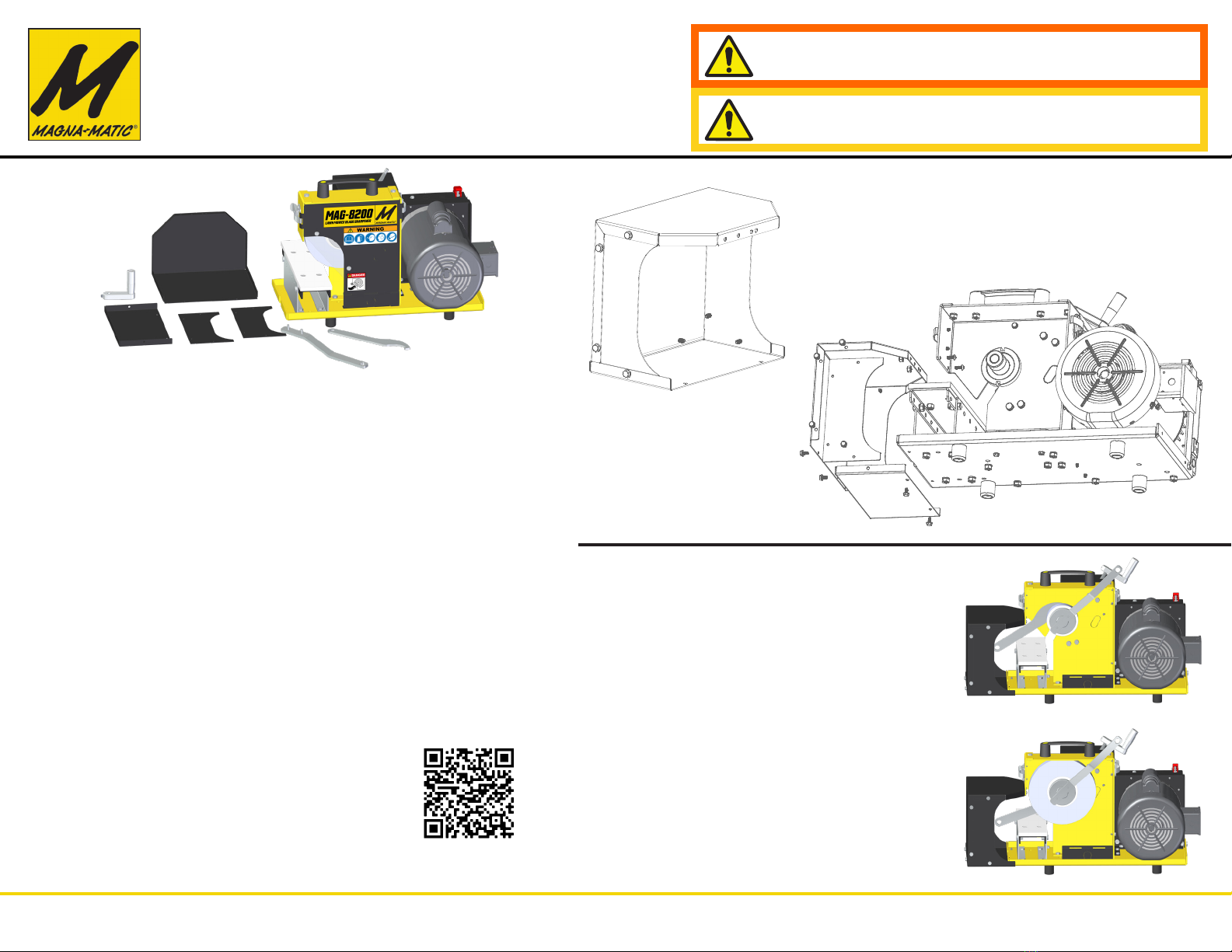
BLADE & SHARPENER PREPARATION
1. Clean the blade to its base material, using the MAG-12008 blade cleaner, or alternate
cleaning process. Inspect the blade for fractures. (never weld mower blades)
2. Check the straightness with the gauge rod of the MAG-1000 blade balancer
(never straighten bent blades)
3. Obtain a balance reading from the MAG-1000 to indicate the light end of the lawn mower
blade. Once the light end is sharpened, that end is complete. The heavy end is used
to remove material for balance. See MAG-1000 instructions for more details on blade
balancing. (never weld mower blades)
4. Adjust the cutting edge angle to 30 degrees.
CONVENTIONAL BLADE SHARPENING
1. Switch the ON/OFF switch to ON position
2. Place the conventional blade on the worktable, you should push and pull the blade
across the grinding wheel. Notice approach the grinding wheel as shown below. Stay
perpindicular to the
rotation of the wheel.
3. Keep firm downward
pressure on the top
of the blade so that
contact is maintained
with the worktable. This
is important because
the angle is referenced
off the worktable and
underside of the blade.
4. The force into the
grinding wheel should
be substantial resulting
in a continuous stream
of sparks and a deep
smooth grinding sound.
5. The grinding process
should be continuous
without interruption until
finished.
ADJUSTING THE EDGE ANGLE
30 Degree Reference Point - When the grinding wheel is lowered to the worktable (almost cutting
the work table corner) you will produce a 30 degree angle on the lawn mower blade. As the grinding
wheel wears and reduces in diameter, continue to lower the grinding wheel to almost touch the work-
table (1/32” space) to maintain a consistent 30 degree edge angle on a blade. As the wheel wears
into an angled shape it will lower deeper into the worktable. Regardless if the grinding wheel is new
or almost used up - you will always want to be as close as the wheel can get to the plastic worktable
(without grinding the plastic) to maintain 30 degrees. If you grind into the plastic worktable you have
now changed this angle reference point.
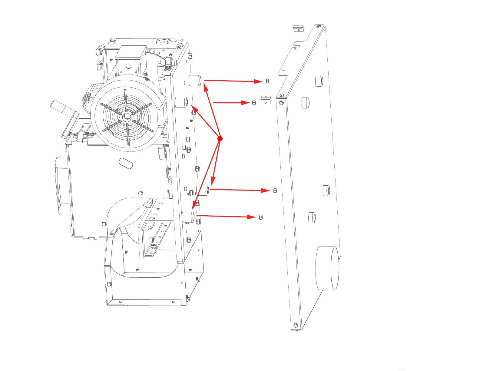
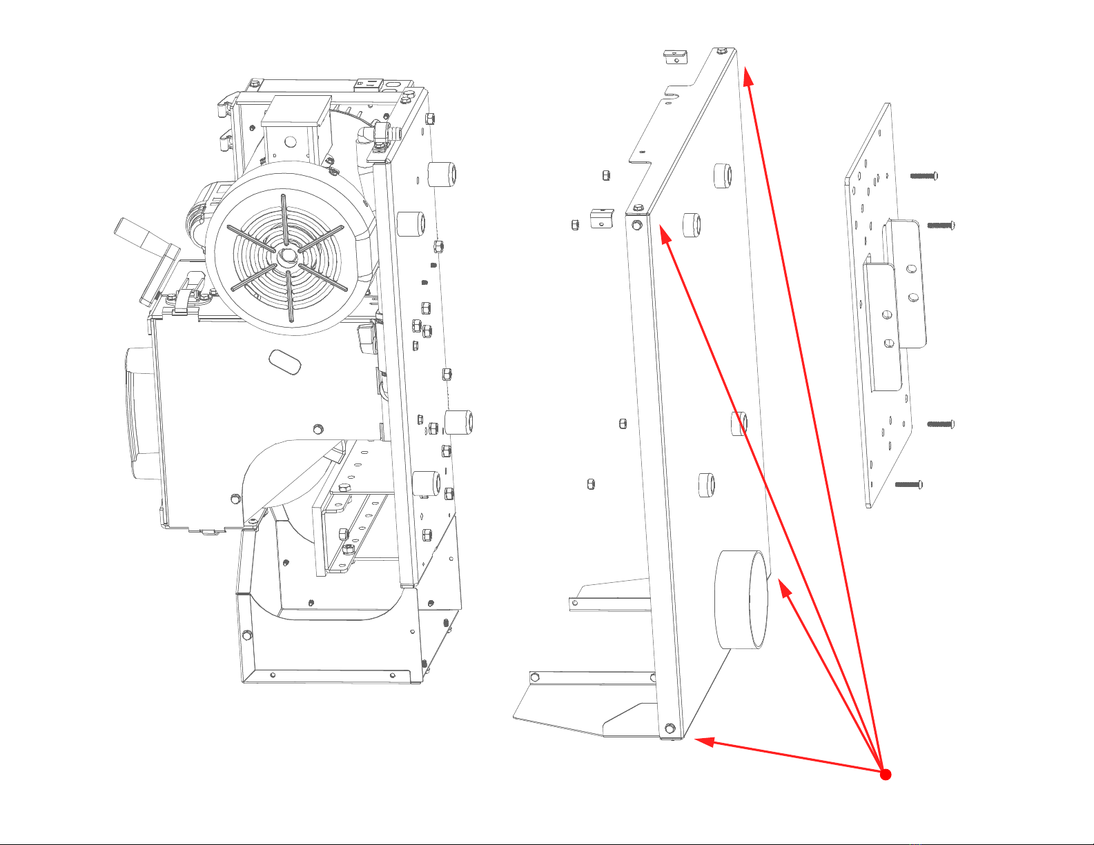
If you have worn out - or accidently ground the plastic worktable - please note there are two pieces
to the worktable. There is an onboard replacement under the top surface. Simply take the four bolts
out and swap the two surfaces. Two worktables must always be installed to keep the 30 degree angle
reference point.
The edge angle can be varied plus or minus the 30 degree reference point via the
adjusting crank.
Raising the grinding wheel will result in a lesser than 30 degree angle
(a more shallow angle.)
Lowering the grinding wheel into the work table (grinding into the work table) will result in a greater
than 30 degree angle (a steeper angle.) Note: you will be creating a new angle reference point. To
make this steeper angle reference point you will grind into the plastic worktable.
ANGLE DETERMINATION
(when sharpener is set to 30 degrees)
If the grinding wheel only grinds the TRAILING EDGE the angle is greater than 30 degrees.
If the grinding wheel only grinds the LEADING EDGE the angle is less than 30 degrees.
HINT: The cutting edge-angle is 30
degrees - when the cutting edge face
width is twice the thickness of the blade.
Cutting Diameter
Cutting Edge
Lift
30°
Cutting Edge
Cutting Tip
Cutting Tip
DANGER WARNING
Keep constant pressure downward to
maintain flat contact with the blade underside and worktable.
Slide the blade back and
forth across the grinding wheel.
Apply pressure into the
grinding wheel to remove
material.
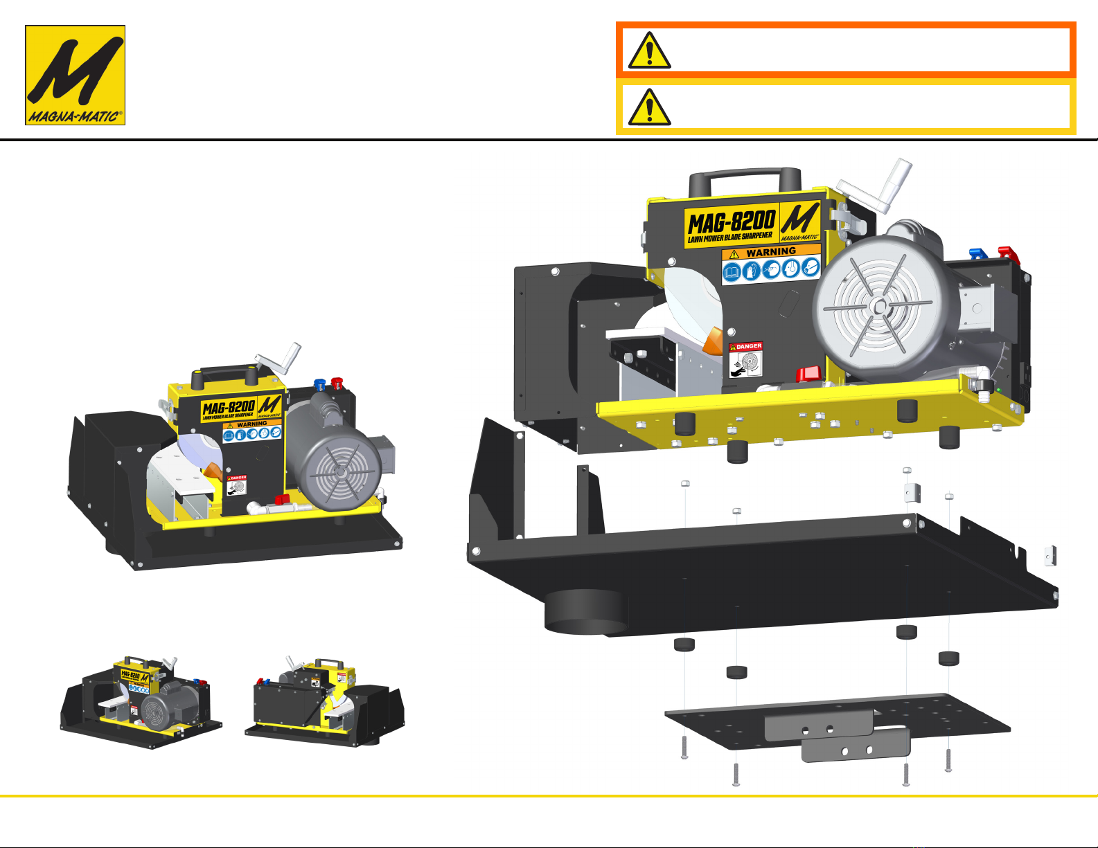
MAG-8200 Sharpener
Overhead-View
Right-Handed
Blade
Left-Handed
Blade