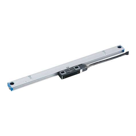
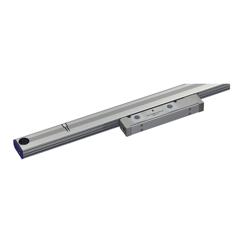
Magnescale SR84 User manual

SR84 / SR85, CH33
取付説明書 / Installation Manual / Anbringungsanleitung /
スケールユニット / Scale Unit / Maßstabseinheit /
お買い上げいただき、ありがとうございます。
ご使用の前に、この取付説明書を必ずお読みください。
ご使用に際しては、この取付説明書どおりお使いください。
お読みになった後は、後日お役に立つこともございますので、必ず保管してください。
本説明書は取付寸法と取付方法についての基本的な項目についてのみ記載したものです。
より詳しい内容については、別売の取扱説明書を参照してください。
Read all the instructions in the installation manual carefully before use and strictly follow
them. Keep the manual for future references.
This manual only contains basic information for the installation dimensions and installation
procedures. Please refer to the Instruction Manual (sold separately) for more detailed
information.
Lesen Sie die ganze Anleitung vor dem Betrieb aufmerksam durch und folgen Sie beim
Betrieb des Geräts den Anweisungen. Bewahren Sie diese Anbringungsanleitung zum
späteren Nachlesen griffbereit auf.
Diese Anleitung enthält nur grundlegende Informationen über die Installationsabmessungen
und Installationsverfahren. Ausführlichere Informationen entnehmen Sie bitte der
Bedienungsanleitung (getrennt erhältlich).
感谢您惠购本产品。
使用之前请务必认真阅读本手册,并且严格按照手册中的规定操作。将此手册留作以后的
参考。
本说明书只对安装尺寸和安装方法的基本项目进行说明,有关详细内容,请参阅另购的使
用说明书。

[For U.S.A. and Canada]
THIS CLASS A DIGITAL DEVICE COMPLIES WITH
PART15 OF THE FCC RULES AND THE CANADIAN
ICES-003. OPERATION IS SUBJECT TO THE
FOLLOWING TWO CONDITIONS.
(1) THIS DEVICE MAY NOT CAUSE HARMFUL
INTERFERENCE, AND
(2) THIS DEVICE MUST ACCEPT ANY
INTERFERENCE RECEIVED, INCLUDING
INTERFERENCE THAT MAY CAUSE
UNDERSIGNED OPERATION.
CET APPAREIL NUMÉRIQUE DE LA CLASSE A
EST CONFORME À LA NORME NMB-003 DU
CANADA.
[ For EU and EFTA countries ]
CE Notice
Marking by the symbol CE indicates compliance with
the EMC directive of the European Community. This
marking shows conformity to the following technical
standards.
EN 55011 Group 1 Class A/1998 A1/1999 A2/2002 :
"Limits and methods of measurement of radio
disturbance characteristics of industrial, scientific and
medical (ISM) radio-frequency equipment"
EN 61000-6-2/2001 :
"Electromagnetic compatibility (EMC) - Part 6-2 :
Generic standards - Immunity for industrial
environments"
警告
本装置を機械指令(EN60204-1)の適合を受ける機器
にご使用の場合は、その規格に適合するように方策
を講じてから、ご使用ください。
Warning
When using this device with equipment governed by
Machine Directives EN 60204-1, measures should be
taken to ensure conformance with those directives.
Warnung
Wenn dieses Gerät mit Ausrüstungsteilen verwendet
wird, die von den Maschinenrichtlinien EN 60204-1
geregelt werden, müssen Maßnahmen ergriffen
werden, um eine Übereinstimmung mit diesen
Normen zu gewährleisten.

SR84 / SR85, CH33
(J) 1
安全のために
当社の製品は安全に充分配慮して設計されています。しかし、操作や設置時にまちがった取扱い
をすると、火災や感電などにより死亡や大ケガなど人身事故につながることがあり、危険です。
また、機械の性能を落としてしまうこともあります。
これらの事故を未然に防ぐために、安全のための注意事項は必ず守ってください。操作や設置、
保守、点検、修理などを行う前に、この「安全のために」を必ずお読みください。
警告表示の意味
このマニュアルでは、次のような表示をしています。表示内容をよく理解し
てから本文をお読みください。
警告
この表示の注意事項を守らないと、火災や感電などにより死亡や大ケガなど
人身事故につながることがあります。
注意
この表示の注意事項を守らないと、感電やその他事故によりケガをしたり周
辺の物品に損害を与えることがあります。
警告
•表示された電源電圧以外での電圧で使用しないでください。火災や感電の原因となる恐れがあ
ります。
•濡れた手による取付作業はおやめください。感電の原因となる恐れがあります。
•本体を分解や改造しないでください。ケガの恐れや、内部回路が破損することがあります。
注意
•作業を行なう前には、装置の状況をよく確かめて作業の安全を確保してください。
•電源などの駆動源は必ず切って作業をしてください。火災や事故の原因となります。
•電源などを入れて動かす場合は、周辺機械や装置などに指を挟まれないように充分注意してく
ださい。
一般的注意事項
以下は当社製品を正しくお使いいただくための一般的注意事項です。個々の詳細な取扱上の注意
は、本取付説明書に記述された諸事項および注意をうながしている説明事項に従い、正しくお使
いください。
•始業または操作時には、当社製品の機能および性能が正常に作動していることを確認してから
ご使用ください。
•当社製品が万一故障した場合、各種の損害を防止するための充分な保全対策を施してご使用く
ださい。
•仕様に示された規格以外での使用または改造を施された製品については、機能および性能の保
証はできませんのでご留意ください。
•当社製品を他の機器と組合せてご使用になる場合は、使用条件、環境などにより、その機能お
よび性能が満足されない場合がありますので、充分ご検討の上ご使用ください。

2(J)
SR84 / SR85, CH33
ML : 測定長
CL : ケーブル長
MG : マシンガイド
注意
•▲面を取付面とします。
•図に指示するねじは、標準付属品です。
•原点信号は、スケールの▽マークとスライダの△マークがほぼ一致したとき、出力されます。マルチポイントと符号
型には、▽マークはありません。
•測定長(ML)を超えてスライダを動かすと破損します。機械の可動長(ストローク)が、測定長(ML)の両端から
10mm以上内側になる設定を推奨します。
■■
■■
■取付面の許容範囲(平行度、平面度)
n ×ø7、ø11ザグリ 深さ6. 5
(取付ねじ M6 ×35)
2 ×ø4.5 ×8.5 (取付ねじM4 ×20)
6角ザグリ深さ5
エアパージ用穴
(M5:両端)
32
30
28
26
24
22
20
19
18
17
16
15
14
13
12
11
10
9
8
7
6
5
4
3
n
2300
2100
1900
1800
1700
1600
1500
1400
1300
1200
1100
1000
900
800
600
700
500
400
300
200
3100
2900
2700
2500
3178
2978
2778
2578
2378
2178
1978
1878
1778
1578
1678
1378
1478
1278
1178
1078
978
878
778
478
678
578
278
378
L2
L1ML
3040
2840
2640
2440
2240
2040
1840
1740
1640
1540
1440
1340
1240
1140
1040
940
840
740
640
540
440
340
240
140
65
(ø8)
100
CH33
(ø11.3)
CL = 3 m, 5 m, 10 m, 15 m
ML
115
21 56
7.5
19.5
78
48.5
19
39
28.5
0.1
5±0.2
0.05
0.1
0.05
MG
0.1
MG
9.2
14.5
3.5
(9)
29
1±0.3
100
12.5
39 L2 = (100 ±0.2) ×(n–1)
100 ±0.2
L1 = ML + 138
(39)
SR84/85
単位:mm

SR84 / SR85, CH33
(J) 3
■スケール、スライダの取付の注意
注意
•スケール取付前に電源は投入しないでください。
•スケールは、スケール本体の開口部を下向きにして取付けてください。
下向きが無理な場合は、横向きとしてください。上向きでは取付けないでください。(図1)
•測定長(ML)を超えてスライダを動かすと破損します。ご注意ください。
•クーラントが直接かかる環境では、クーラントが直接かからないよう、スケールにカバーを取
付けてください。(図2)
SR84 / SR85
•スライダホルダは、輸送時のスライダ固定用のものです。取付の基準とはなりません。
•スライダホルダは、スライダを固定する直前まで、できるだけ外さないでください。
•スライダホルダを外しても、スライダはスライダに設けられた樹脂フックにより、スケール
本体に対しておおよその位置関係が維持されます。
•無理にスライダをねじるなどの力を加えると、樹脂フックが外れてしまいます。樹脂フックが
外れたときは樹脂フックを元の位置に戻してから取付作業を行なってください。(図4参照)
図2図1
開口部下向き
( )
開口部横向き
( )
開口部上向き
( )
クーラント
図3
図4
スライダホルダL
スライダホルダR
レバー
(この位置に回す)
レバー
(この位置に回す)
手順2
手順2
手順1
手順1
樹脂フック
樹脂フック
輸送/固定時の状態 スライダホルダの取外し方法
1.ロックの解除
左右のスライダホルダのレバーを反時計方向(イラスト
の位置)に回します。
2.取り外し
スライダホルダを外側にスライドさせ、スケールから
取外します。

4(J)
SR84 / SR85, CH33
•スケールを取付ける前に、必ず取付面(または取付用ブラケット)のアライメントが規格内で
あることを確認してください。
•スケール取付用ブラケットを使用する際は、スケール全長にわたる長さのブラケットを使用し
てください。分割されたブラケットを使用する場合でも、必ず取付用ブラケットのアライメン
トが規格内であることを確認してください。
•スケール本体背面が取付基準となります。
•スケール取付ねじは一度に締めず、仮締めし、平行度を出してから規定トルク(図5参照)で締
めつけてください。
図5
スケール : M6 ×35 (9 N
•
m) スライダ: M4 ×20 (2.7 N
•
m)
突き当てる

SR84 / SR85, CH33
(J) 5
取付例
例1 (推奨):ブラケットにスケールとスライダの突き当てを設ける場合
突き当てを設けると、スケールの取付精度が向上します。また、スケールの再取付が簡単になり
ます。
1. スケール用ブラケットのマシンガイドに対する平行度を確認、調整し、固定します。
図のように、分割されたブラケットを使用する場合でも、ブラケット全長で平行度を調整し
てください。
図6
図7
単位:mm
単位:mm
0.05
以下
0.05
以下
50
0.05
MG
0.05
MG
スケール用
ブラケット
または
0.05
以下
78
±0.3
5
±0.2
0.05
MG
78
±0.3
78
±0.3
スライダ用ブラケット
スケール用ブラケット
スライダ用ブラケット
2. スライダ用ブラケットの高さと平行度を確認、調整し、固定します。

6(J)
SR84 / SR85, CH33
図8
3. スケールを各突き当て面に突き当てて、取付けます。
例2:ブラケットにスケールとスライダの突き当てを設けない場合
1. スケール用ブラケットとスライダ用ブラケットのマシンガイドに対する平行度を調整し、固
定します。
スライダ用ブラケットのスケール用ブラケットに対する高さと平行度を調整し、固定します。
図9
単位:mm
0.05
以下
78
±0.3
5
±0.2
78
±0.3
0.05
MG
0.05
MG
スライダ用ブラケット
スライダ用ブラケット
スケール用ブラケット

SR84 / SR85, CH33
(J) 7
スペーサ(t=1.0mm)
図11
2. スケール背面をダイヤルゲージで測定しながら、スケール背面のマシンガイドに対する平行
度を調整し、固定ねじを締めつけます。
<測定方法>
スケール本体背面の取付穴位置付近を測定してください。
図10
3. スケールとスライダの隙間に、付属品のスペーサ(t=1.0mm)を挿入し、スライダをスケー
ルに突き当てながら、スライダの位置調整を行ないます。
■空気導入およびオイル・ルブリカントについて
エンドキャップ部には、標準で空気導入およびオイル・ルブリカント用のM5タップ穴があります。
詳細資料は別売の取扱説明書を参照してください。
単位:mm
0.1
MG

8(J)
SR84 / SR85, CH33
■CH33(先バラケーブル)信号仕様
ケーブル色相 SR84 SR85
4線(注1) 2線(注2)
茶0V0V0V
黒0V0V0V
緑+5V +5V +5V
紫+5V +5V +5V
青ACNT
(注3) CNT(注3)
黄–AN.C.(注4) N.C.(注4)
橙BSDN.C.
(注4)
灰–B–SD N.C.(注4)
赤ZRQ SD/RQ
白–Z–RQ –SD/–RQ
(注1) 4線:フルデュプレックス方式
(注2) 2線:ハーフデュプレックス方式
(注3) CNT端子はサービスメンテナンス用です。結線しないでください。
(注4) N.C.:信号は接続されていません。
+5Vと0Vは各々2本ずつありますので、必ず2本ずつ結線してください。
結線が1本の場合は、ケーブルでの電圧降下により、動作しない場合があります。
CH33

(E) 1
SR84 / SR85, CH33
Safety Precautions
Magnescale Co., Ltd. products are designed in full consideration of safety. However, improper handling
during operation or installation is dangerous and may lead to fire, electric shock or other accidents resulting
in serious injury or death. In addition, these actions may also worsen machine performance.
Therefore, be sure to observe the following safety precautions in order to prevent these types of accidents,
and to read these “Safety Precautions” before operating, installing, maintaining, inspecting, repairing or
otherwise working on this unit.
Warning indication meanings
The following indications are used throughout this manual, and their contents should
be understood before reading the text.
Warning
Failure to observe these precautions may lead to fire, electric shock or other accidents
resulting in serious injury or death.
Caution
Failure to observe these precautions may lead to electric shock or other accidents
resulting in injury or damage to surrounding objects.
Warning
•Do not use this unit with voltages other than the specified supply voltages as this may result in fire or
electric shock.
•Do not perform installation work with wet hands as this may result in electric shock.
•Do not disassemble or modify the unit as this may result in injury or damage the internal circuits.
Caution
•Be sure to check the machine and device conditions to ensure work safety before working on the machine.
•Be sure to cut off the power supply and other sources of drive power before working on the machine.
Failure to do so may result in fire or accidents.
•When turning on the power supply or other sources of drive power to operate the machine, take care not
to catch your fingers in peripheral machines and devices.
General Precautions
When using Magnescale Co., Ltd. products, observe the following general precautions along with those
given specifically in this manual to ensure proper use of the products.
•Before and during operations, be sure to check that our products function properly.
•Provide adequate safety measures to prevent damages in case our products should develop malfunctions.
•Use outside indicated specifications or purposes and modification of our products will void any warranty
of the functions and performance as specified of our products.
•When using our products in combination with other equipment, the functions and performance as noted
in this manual may not be attained, depending upon operating environmental conditions. Make full study
of the compatibility in advance.

2(E)
SR84 / SR85, CH33
■■
■■
■Installation Surface Allowable Ranges (Parallelism and Flatness)
ML : Measuring length
CL : Cable length
MG : Machine guide
Notes
•The installation surface is indicated by surface.
• The screws indicated in the drawing are supplied as accessories.
•The reference point signal is output when the mark on the scale and mark on the slider are nearly aligned.
There are no mark for multi-point and reference mark.
• The scale will be damaged if the slider moved outside the measuring length (ML). It is recommended that the
machine movable length (stroke) be set at least 10 mm inward from each end of the measuring length (ML).
Air purge hole
(M5: Both ends)
32
30
28
26
24
22
20
19
18
17
16
15
14
13
12
11
10
9
8
7
6
5
4
3
n
2300
2100
1900
1800
1700
1600
1500
1400
1300
1200
1100
1000
900
800
600
700
500
400
300
200
3100
2900
2700
2500
3178
2978
2778
2578
2378
2178
1978
1878
1778
1578
1678
1378
1478
1278
1178
1078
978
878
778
478
678
578
278
378
L2
L1ML
3040
2840
2640
2440
2240
2040
1840
1740
1640
1540
1440
1340
1240
1140
1040
940
840
740
640
540
440
340
240
140
65
(ø8)
100
CH33
(ø11.3)
CL = 3 m, 5 m, 10 m, 15 m
ML
115
21 56
7.5
19.5
78
48.5
19
39
28.5
0.1
5
±0.2
0.05
0.1
0.05
MG
0.1
MG
9.2
14.5
3.5
(9)
29
1
±0.3
100
12.5
39 L2 = (100
±0.2
) ×(n–1)
100
±0.2
L1 = ML +138
(39)
SR84/85
Unit: mm
2 ×ø4.5 ×8.5
(mounting screws M4 ×20)
Hexagonal
countersunk
depth 5
n ×ø7, ø11 countersunk depth 6.5
(mounting screws M6 ×35)

(E) 3
SR84 / SR85, CH33
SR84 / SR85
■■
■■
■Scale and slider installation notes
Notes
•Do not turn on the power before installing the scale.
•Install the scale with the opening on the scale unit facing downward. If the opening cannot be turned
downward, it should face horizontally. Never install it facing upward. (Fig. 1)
•Be aware that the scale will be damaged if slider moved outside the measuring length (ML).
•In environments where coolant can splash directly on the scale, be sure to mount a cover on the scale to
protect the scale from splashing. (Fig. 2)
•The slider holders are used to secure the slider in place during transport. They are not guides for installation.
•Do not take off the slider holders, if possible, until immediately before securing the slider.
•Even if the slider holders are removed, the plastic hook provided on the slider allows the slider to
maintain an approximate positional relationship with the scale unit.
•The plastic hook can come off if the slider is forcibly twisted or other excessive force is applied. If the
plastic hook comes off, return the plastic hook back to its original position before performing the
installation. (See Fig. 4.)
Fig. 1 Fig. 2
Fig. 3
Opening facing
downward
( )
Opening facing
horizontally
( )
Opening
facing upward
( )
Coolant
Slider holder L
State when Transporting / Securing in Place
Slider holder R
Lever
(Turn to this position)
Lever
(Turn to this position)
Step 2
Step 2
Step 1
Step 1
Plastic hook
Plastic hook
Removing the slider holder
1. Removing the lock
Turn the right and left slider holder levers in the
counterclockwise direction (position in the illustration).
2. Removing
Slide the slider holder to the outside, and remove from
the scale.
Fig. 4

4(E)
SR84 / SR85, CH33
•Before installing the scale, check that the alignment of the installation surface (or installation brackets) is
within the standards.
•Use a scale installation bracket, where applicable, having a length covering the entire scale length. Even
when using divided brackets, be sure to always check that the alignment of the installation brackets is
within the standards.
•The rear surface of the scale unit is used as the installation guide.
•Loosely turn the mounting screws first. Determine the alignment and then tighten the screws to fasten the
scale. (See Fig. 5.)
Fig. 5
Scale : M6
×
35 (9 N•m) Slider : M4
×
20 (2.7 N•m)
Bring into contact

(E) 5
SR84 / SR85, CH33
Fig. 7
Installation example
Example 1 (recommended): Installation when a stop surface of the scale and slider is
made with the bracket
Scale installation accuracy is improved when a stop surface is made. This also simplifies reinstallation of the
scale.
1. Check and adjust the scale bracket’s parallelism with respect to the machine guide, and then secure in
place.
Even when using divided brackets, adjust the parallelism over the entire bracket length as shown in the
figure.
2. Check and adjust the height and parallelism of the slider bracket, and then secure in place.
Fig. 6
Unit: mm
Unit: mm
0.05
or less
0.05 or less
50
0.05
MG
0.05
MG
Scale
bracket
Or
0.05 or less
78
±0.3
5
±0.2
0.05
MG
78
±0.3
78
±0.3
Slider bracket
Scale bracket
Slider bracket

6(E)
SR84 / SR85, CH33
Fig. 8
3. Bring the scale into contact with the stop surfaces and install.
Example 2: Installation when a stop surface of the scale and slider is not made with the
bracket
1. Adjust the parallelism of the scale bracket and slider bracket with respect to the machine guide, and then
secure in place. Adjust the height and parallelism of the slider bracket with respect to the scale bracket,
and then secure in place.
Fig. 9
Unit: mm
0.05 or less
78 ±0.3
5±0.2
78 ±0.3
0.05
MG
0.05
MG
Slider bracket
Slider bracket
Scale bracket

(E) 7
SR84 / SR85, CH33
Fig. 11
Fig. 10
2. Adjust the parallelism with respect to the machine guide of the scale rear while measuring the scale rear
with a dial gauge. Tighten the set screws.
<Measurement method>
Measure near the installation hole positions at the scale unit rear.
3. Insert the supplied spacer (t = 1.0 mm) in the space between the scale and slider, and then adjust the
slider position while bringing the slider into contact with the scale.
■■
■■
■Air injection and oil lubrication
In the standard configuration, the end cap section is provided with an M5 tap hole for air injection and oil
lubrication. For more detailed information, please refer to the Instruction Manual (sold separately).
Unit: mm
0.1
MG
spacer(t=1.0mm)

8(E)
SR84 / SR85, CH33
CH33
■■
■■
■CH33 (cable with unterminated end) Signal Specifications
Cable color SR84 SR85
Full duplex Half duplex
Brown 0 V 0 V 0 V
Black 0 V 0 V 0 V
Green +5 V +5 V +5 V
Violet +5 V +5 V +5 V
Blue A CNT(Note 1) CNT(Note 1)
Yellow –A N.C.(Note 2) N.C.(Note 2)
Orange B SD N.C.(Note 2)
Gray –B –SD N.C.(Note 2)
Red Z RQ SD/RQ
White –Z –RQ –SD/–RQ
Note 1: The CNT terminal is for service maintenance. Do not connect.
Note 2: N.C.: Signal is not connected.
There are always two cables each for +5 V and 0 V, and so be sure to connect these cables in pairs. If only
one cable is connected, the scale may not operate due to the voltage drop in the cable.

(G) 1
SR84 / SR85, CH33
Sicherheitsmaßnahmen
Bei dem Entwurf von Magnescale Co., Ltd. Produkten wird größter Wert auf die Sicherheit gelegt. Unsachgemäße
Handhabung während des Betriebs oder der Installation ist jedoch gefährlich und kann zu Feuer, elektrischen
Schlägen oder anderen Unfällen führen, die schwere Verletzungen oder Tod zur Folge haben können. Darüber
hinaus kann falsche Anwendung die Leistung der Maschine verschlechtern.
Beachten Sie daher unbedingt die besonders hervorgehobenen Sicherheitshinweise in dieser Bedienungsanleitung,
um derartige Unfälle zu verhüten, und lesen Sie die folgenden Sicherheitsmaßnahmen vor der Inbetriebnahme,
Installation, Wartung, Inspektion oder Reparatur dieses Gerätes oder der Durchführung anderer Arbeiten durch.
Bedeutung der Warnhinweise
Bei der Durchsicht dieses Handbuchs werden Sie auf die folgenden Hinweise und Symbole
stoßen. Machen Sie sich mit ihrer Bedeutung vertraut, bevor Sie den Text lesen.
Warnung
Eine Missachtung dieser Hinweise kann zu Feuer, elektrischen Schlägen oder anderen
Unfällen führen, die schwere Verletzungen oder Tod zur Folge haben können.
Vorsicht
Eine Missachtung dieser Hinweise kann zu elektrischen Schlägen oder anderen Unfällen
führen, die Verletzungen oder Sachbeschädigung der umliegenden Objekte zur Folge haben
können.
Warnung
•
Betreiben Sie dieses Gerät nur mit der vorgeschriebenen Versorgungsspannung, da anderenfalls die Gefahr von
Feuer oder elektrischen Schlägen besteht.
•
Führen Sie Installationsarbeiten nicht mit nassen Händen aus, da hierbei die Gefahr elektrischer Schläge
besonders groß ist.
•
Unterlassen Sie jeden Versuch, das Gerät zu zerlegen oder umzubauen, da dies zu Verletzungen oder
Beschädigung der internen Schaltungen führen kann.
Vorsicht
•
Überprüfen Sie vor Arbeitsbeginn unbedingt den Zustand von Maschine und Vorrichtungen, um die
Arbeitssicherheit zu gewährleisten.
•
Schalten Sie vor Arbeiten an der Maschine unbedingt die Stromzufuhr und andere Antriebsstromquellen aus.
Anderenfalls besteht Brand- oder Unfallgefahr.
•
Achten Sie beim Einschalten der Stromversorgung usw. zum Betrieb der Maschine darauf, dass Sie sich nicht
die Finger in peripheren Maschinen und Vorrichtungen klemmen.
Allgemeine Vorsichtsmaßregeln
Beachten Sie bei Verwendung unserer Produkte die folgenden allgemeinen Vorsichtsmaßregeln neben den in
diesem Handbuch speziell vermerkten Hinweisen, um korrekten Gebrauch der Produkte zu gewährleisten.
•
Vergewissern Sie sich vor und während des Betriebs, dass das Produkt einwandfrei funktioniert.
•
Treffen Sie angemessene Sicherheitsmaßnahmen, um im Falle von Funktionsstörungen Schäden zu vermeiden.
•
Der Einsatz außerhalb der angegebenen Spezifikationen oder Zwecke und die Modifikation unserer Produkte
haben den Verfall der Garantie auf die angegebenen Funktionen und Leistungen unserer Produkte zur Folge.
•
Bei Verwendung unserer Produkte in Verbindung mit anderen Geräten werden je nach den
Betriebsumgebungsbedingungen die in dieser Anleitung angegebenen Funktionen und Leistungen möglicherweise
nicht erzielt. Daher sollte die Kompatibilität vorher gründlich überprüft werden.

2(G)
SR84 / SR85, CH33
■■
■■
■Montageflächen-Toleranzbereiche (Parallelität und Ebenheit)
Frischluftspülungsbohrung
(M5:BeideEnden)
32
30
28
26
24
22
20
19
18
17
16
15
14
13
12
11
10
9
8
7
6
5
4
3
n
2300
2100
1900
1800
1700
1600
1500
1400
1300
1200
1100
1000
900
800
600
700
500
400
300
200
3100
2900
2700
2500
3178
2978
2778
2578
2378
2178
1978
1878
1778
1578
1678
1378
1478
1278
1178
1078
978
878
778
478
678
578
278
378
L2
L1ML
3040
2840
2640
2440
2240
2040
1840
1740
1640
1540
1440
1340
1240
1140
1040
940
840
740
640
540
440
340
240
140
65
(ø8)
100
CH33
(ø11,3)
CL = 3 m, 5 m, 10 m, 15 m
ML
115
21 56
7,5
19,5
78
48,5
19
39
28,5
0,1
5±0,2
0,05
0,1
0,05
MG
0,1
MG
9,2
14,5
3,5
(9)
29
1±0,3
100
12,5
39 L2 = (100 ±0,2)
×
(n–1)
100 ±0,2
L1 = ML +138
(39)
SR84/85
Einheit: mm
2 ×ø4,5 ×8,5
(Befestigungsschrauben M4 ×20)
Hexagonal,
Senkungstiefe 5
n ×ø7, ø11 Senkungstiefe 6,5
(Befestigungsschrauben M6 ×35)
ML : Messlänge
CL : Kabellänge
MG : Maschinenführung
Hinweise
•Die Montagefläche ist durch die Fläche gekennzeichnet.
• Die in der Zeichnung gezeigten Schrauben sind im Lieferumfang enthalten.
•Das Bezugspunktsignal wird ausgegeben, wenn die Markierung am Maßstab nahezu mit der Markierung am
Schieber fast übereinstimmt. Es gibt keine Markierung für den Mehrpunkt und die Bezugsmarke.
• Der Maßstab wird beschädigt, falls der Schieber über die Messlänge (ML) hinaus bewegt wird. Es wird empfohlen,
die Bewegungslänge (Hub) der Maschine auf mindestens 10 mm innerhalb beider Enden der Messlänge (ML)
einzustellen.
This manual suits for next models
2
Table of contents
Languages:
Other Magnescale Scale manuals

Magnescale
Magnescale PL25 User manual

Magnescale
Magnescale SmartSCALE SQ57-Z Series User manual

Magnescale
Magnescale SmartSCALE SQ57 User manual

Magnescale
Magnescale SR138-025R User manual

Magnescale
Magnescale RU97-2048 Z Series User manual

Magnescale
Magnescale SR27A-AZ Series User manual

Magnescale
Magnescale SJ300 Series Owner's manual

Magnescale
Magnescale SJ300 Series Owner's manual

Magnescale
Magnescale SJ300 SJ300 User manual

Magnescale
Magnescale SmartSCALE SQ47-Z Series User manual